$ 0
0
$ 0
0

Bobcat 3400 Utility Vehicle Service Manual (SN AJNT11001-AJNT99999)

Format: PDF (Printable Document)

File Language: English

File Pages: 535

File Size: 14.52 MB (Speed Download Link)

Brand: Bobcat

Model: 3400 Utility Vehicle

Book No: 6989602

Serial No: SN AJNT11001-AJNT99999

Type of Document: Service Manual

Categories: ,

$ 45

Share:

Bobcat 3400 Utility Vehicle Service Manual (SN AJNT11001-AJNT99999)

The Bobcat 3400 utility vehicle is the runaround machine on a lot of jobsites and farms, hauling materials, tools, and people all day. When it starts losing power, eating belts, or throwing electrical gremlins, the service manual is what the mechanic reaches for. Around my shop, this is the book you need when you're past basic maintenance and you're actually tearing into systems and chasing specs. If you're trying to keep a 3400 in the AJNT11001-AJNT99999 serial range ready to work, this is the right level of detail.

What this manual helps you do

  • Diagnose no-start, low power, or stalling issues with engine and fuel system tests
  • Trace and repair electrical faults using proper wiring diagrams and step-by-step checks
  • Check and adjust drivetrain components, clutches, and drive belts after wear or replacement
  • Rebuild or replace suspension, steering, and brake parts with correct disassembly and reassembly procedures
  • Set and verify hydraulic and mechanical linkages so dump, tow, and utility functions work as they should

Who this is for

This is for shop mechanics, field techs, rental yards, and owner-operators who are ready to pull parts off the machine and put them back on correctly. If you just need operating tips or fluid types and intervals, you want the operator's handbook instead, not this service manual.

FAQ

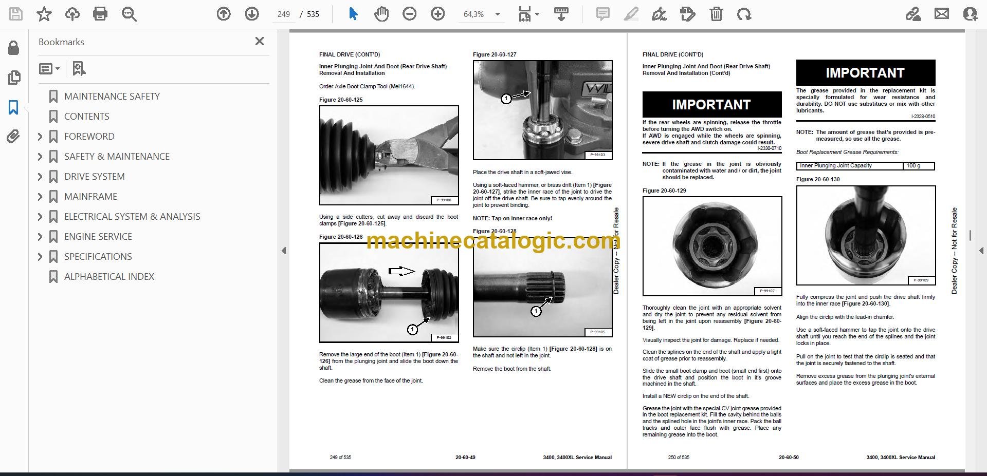
Q: Is this a searchable PDF and are the wiring diagrams readable?

A: Yes, these manuals are normally supplied as searchable PDFs and the wiring diagrams are designed to be zoomed in clearly on a screen.

Q: How do I know if it fits my 3400?

A: If your Bobcat 3400 utility vehicle serial number falls between AJNT11001 and AJNT99999, this is the correct manual family for your machine.

Q: Is this what I need for real repairs, or just routine service?

A: This is the workshop service manual, so it's meant for real troubleshooting, teardown, and repair, not just basic maintenance.

Bottom line, if you own or maintain a Bobcat 3400 in the AJNT11001-AJNT99999 range and you plan to do your own repairs beyond oil and filters, this is the manual you want.

📘 Show Index

Table of Contents:

  • MAINTENANCE SAFETY
  • CONTENTS
  • FOREWORD
    • FOREWORD
    • SAFETY INSTRUCTIONS
    • FIRE PREVENTION
      • Maintenance
      • Operation
      • Electrical
      • Fueling
      • Starting
      • Spark Arrester Exhaust System
      • Welding And Grinding
      • Fire Extinguishers
    • SERIAL NUMBER LOCATIONS
      • Utility Vehicle Serial Number
      • Engine Serial Number
    • DELIVERY REPORT
    • UTILITY VEHICLE IDENTIFICATION (3400)
    • UTILITY VEHICLE IDENTIFICATION (3400XL)
  • SAFETY & MAINTENANCE
    • LIFTING AND BLOCKING THE UTILITY VEHICLE
      • Procedure
    • ROLLOVER PROTECTIVE STRUCTURE (ROPS)
      • Description
    • TRANSPORTING THE UTILITY VEHICLE ON A TRAILER
      • Loading And Unloading
      • Fastening
    • TOWING THE UTILITY VEHICLE
      • Procedure
    • SERVICE SCHEDULE
      • Chart
    • AIR CLEANER SERVICE
      • Pre-Filter Element
      • Replacing Filter Element
      • Engine Breather Filter
    • ENGINE COOLING SYSTEM
      • Checking Level
      • Cleaning
      • Removing And Replacing Coolant
    • FUEL SYSTEM
      • Fuel Specifications
      • Filling The Fuel Tank
      • Filling A Portable Fuel Container
    • ENGINE LUBRICATION SYSTEM
      • Checking And Adding Engine Oil
      • Engine Oil
      • Removing And Replacing Oil And Filter
      • Oil Pump Priming Procedure
    • CONTINUOUS VARIABLE TRANSMISSION (CVT)
      • CVT Drying
      • CVT Filter
    • GEARCASE (S/N AJNT19999 AND AJNV19999 & BELOW)
      • Checking Transmission Fluid
      • Transmission Fluid
      • Adding Transmission Fluid
      • Removing And Replacing Transmission Fluid
      • Checking Front Gearcase Fluid
      • Front Gearcase Fluid
      • Adding Front Gearcase Fluid
      • Removing And Replacing Front Gearcase Fluid
    • GEARCASE (S/N AJNT20001 & ABOVE AND AJNV20001 & ABOVE)
      • Checking Transmission Fluid
      • Transmission Fluid
      • Adding Transmission Fluid
      • Removing And Replacing Transmission Fluid
      • Checking Front Gear Case Fluid
      • Front Gear Case Fluid
      • Adding Front Gear Case Fluid
      • Removing And Replacing Front Gear Case Fluid
    • TIRE MAINTENANCE
      • Tires
      • Tire Tread Depth
      • Axle And Wheel Nut Torque
      • Wheel Removal And Installation
      • Mounting
      • Tire Pressure
    • SPARK ARRESTER MUFFLER
      • Cleaning Procedure
    • UTILITY VEHICLE STORAGE AND RETURN TO SERVICE
      • Storage
      • Return To Service
    • STOPPING THE ENGINE AND LEAVING THE UTILITY VEHICLE
      • Procedure
    • SEAT BELT
      • Inspection And Maintenance
    • LUBRICATING THE UTILITY VEHICLE
      • Lubrication Locations
  • DRIVE SYSTEM
    • BRAKE
      • General Specifications
      • Torque Specifications
      • System Service Notes
      • Noise Troubleshooting
      • System Troubleshooting
      • Hydraulic Brake System Operation
      • System Parts Identification
      • Master Cylinder Removal And Installation
      • Foot Brake Pedal Removal And Installation
      • Bleeding / Fluid Removal And Installation
      • Brake Inspection
      • Brake Pad Inspection
      • Burnishing
    • BRAKE (FRONT)
      • Pad Removal
      • Pad Installation
      • Caliper Removal
      • Caliper Parts Identification
      • Caliper Disassembly
      • Caliper Inspection
      • Caliper Assembly
      • Caliper Installation
      • Disc Inspection
      • Disc Removal And Installation
    • BRAKE (REAR) (S/N AJNT11001 & ABOVE)
      • Pad Removal
      • Pad Installation
      • Caliper Removal
      • Caliper Parts Identification
      • Caliper Disassembly
      • Caliper Inspection
      • Caliper Assembly
      • Caliper Installation
      • Disc Inspection
      • Disc Removal And Installation
    • BRAKE (REAR) (S/N AJNV11001 & ABOVE)
      • Pad Removal
      • Pad Installation
      • Caliper Removal
      • Caliper Parts Identification
      • Caliper Disassembly
      • Caliper Inspection
      • Caliper Assembly
      • Caliper Installation
      • Disc Inspection
      • Disc Removal And Installation
    • BRAKE (PARK)
      • Inspection And Maintenance
      • Parts Identification
      • Lever Removal And Installation
      • Cable Tension Inspection
      • Cable Adjustment
      • Caliper Removal
      • Caliper Parts Identification
      • Caliper Disassembly
      • Caliper Inspection
      • Pad Installation
      • Caliper Assembly
      • Disc Inspection
      • Disc Removal And Installation
      • Caliper Installation
    • GEARCASE (TRANSMISSION)
      • General Operation
      • System Troubleshooting
      • Shift Lever Removal And Installation
      • Shift Cable Inspecting
      • Shift Cable Adjustment
      • Removal And Installation
      • Parts Identification
      • Disassembly
      • Gear Cluster Disassembly
      • Snorkel Shaft Removal / Disassembly
      • Snorkel / Output Gear Backlash Procedure
      • Assembly
    • DRIVE BELT
      • Removal
      • Installation
      • Belt Inspection
      • Belt Damage
    • CONTINUOUS VARIABLE TRANSMISSION (CVT)
      • CVT System Overview
      • Drive Clutch Operation
      • Driven Clutch Operation
      • CVT Break-In (Drive Belt / Clutches)
      • Maintenance And Inspection
      • Overheating Troubleshooting
      • System Troubleshooting
      • CVT Sealing, Guard And Ducting Components Parts Identification
      • CVT (Outer) Cover Removal And Installation
      • CVT (Inner) Cover Removal And Installation
      • Clutch Alignment
      • Clutch Offset
      • Clutch Center Distance
    • CONTINUOUS VARIABLE TRANSMISSION (CVT) (DRIVE CLUTCH)
      • Removal And Installation
      • Spring Specifications
      • Shift Weights
      • Parts Identification (S/N AJNT11001 & Above)
      • Parts Identification (AJNV11001 & Above)
      • Inspection
      • Button To Tower Clearance Inspection
      • Disassembly (S/N AJNT11001 & Above)
      • Disassembly (S/N AJNV11001 & Above)
      • Moveable Sheave Bushing Removal And Installation
      • Clutch Cover Bushing Removal And Installation
      • Assembly (S/N AJNT11001 & Above)
      • Assembly (S/N AJNV11001 & Above)
    • CONTINUOUS VARIABLE TRANSMISSION (CVT) (DRIVEN CLUTCH)
      • Removal And Installation
      • Parts Identification
      • Disassembly
      • Bushing Removal
      • Bushing Installation
      • Assembly
    • FINAL DRIVE
      • Description
      • Front Hub Removal
      • Hubstrut Bearing Removal And Installation
      • Front Hub Installation
      • Front Drive Shaft Removal And Installation
      • Outer CV Joint And Boot (Front Drive Shaft) Removal And Installation
      • Propshaft Removal And Installation (S/N AJNT11001 & Above)
      • Propshaft Removal And Installation (S/N AJNV11001 & Above)
      • Support Bearing Removal And Installation (S/N AJNV11001 & Above)
      • Propshaft U-Joint Disassembly
      • Propshaft U-Joint Assembly
      • Front Gearcase Operation
      • Front Gearcase Removal And Installation
      • Front Gearcase Parts Identification
      • Front Gearcase Disassembly / Inspection
      • Front Gearcase Assembly / Inspection
      • Setting Ring Gear Backlash
      • Rear Bearing Carrier Inspection
      • Rear Bearing Carrier Removal
      • Rear Bearing Carrier Disassembly And Assembly
      • Rear Bearing Carrier Installation
      • Rear Drive Shaft Removal And Installation
      • Outer CV Joint And Boot (Rear Drive Shaft) Removal And Installation
      • Inner Plunging Joint And Boot (Rear Drive Shaft) Removal And Installation
  • MAINFRAME
    • ROLL OVER PROTECTIVE STRUCTURE (ROPS)
      • Removal And Installation
    • OPERATOR SEAT
      • Seat Back Removal And Installation
      • Seat Base Removal And Installation
      • Seat Belt Removal And Installation
    • DASH
      • Front Access Cover Removal And Installation
      • Left Dash Removal And Installation
      • Right Dash Removal And Installation
      • Center Dash Removal And Installation
    • BUMPER COVER
      • Removal And Installation
    • STRUT
      • Strut Cartridge Removal And Installation
    • STEERING COLUMN (S/N AJNT19999 & BELOW AND AJNV19999 & BELOW)
      • Steering Wheel Removal And Installation
      • Parts Identification
      • Steering Shaft Removal And Installation
    • STEERING COLUMN (S/N AJNT20001 & ABOVE AND S/N AJNV20001 & ABOVE)
      • Description
      • Tilt Steering Shock Removal And Installation
      • Parts Identification
      • Steering Wheel Removal And Installation
      • Steering Shaft Removal And Installation
      • Pivot Tube Bearing Removal And Installation
    • STEERING BOX
      • Removal And Installation
    • FUEL TANK
      • Removal And Installation
    • SHOCKS
      • Removal And Installation
      • Shock Spring Removal And Installation
    • CONTROL ARMS
      • Removal And Installation (Rear Lower Arm)
      • Removal And Installation (Upper Arm)
      • Removal And Installation (Rear Upper Arm)
      • Removal And Installation (Front Arm)
      • Inspection
      • Ball Joint Removal And Installation
    • TIE ROD
      • Description
      • Removal And Installation
      • Toe Adjustment Procedure
    • TAILGATE
      • Removal And Installation
      • Latch Removal And Installation
    • CARGO BOX
      • Removal And Installation
    • FENDER
      • Removal And Installation (Front)
      • Removal And Installation (Rear)
      • Flare Removal And Installation
    • REAR STABILIZER BAR / LINKAGE
      • Removal And Installation
      • Inspection
  • ELECTRICAL SYSTEM & ANALYSIS
    • ELECTRICAL SCHEMATICS
    • ELECTRICAL SYSTEM INFORMATION
      • Glossary Of Electrical Symbols
      • Description
      • Troubleshooting
      • Fuse And Relay Location – Cab Panel
    • BATTERY
      • Removal And Installation
      • Servicing
      • Battery Charging
      • Using A Booster Battery (Jump Starting)
    • CHARGING SYSTEM
      • Current Draw – Key OFF
      • Break Even Test
      • Stator Testing
      • Stator Plate Assembly Removal
      • Stator Plate Assembly Installation
      • Testing Flow Chart
    • STARTER SYSTEM
      • Testing
      • Removal And Installation
      • Parts Identification
      • Starting Testing Flow Chart
    • REGULATOR / RECTIFIER
      • Location
      • Removal And Installation
      • Testing
    • LIGHTS
      • Headlight Removal And Installation
      • Headlight Adjustment
      • Tail Light / Brake Light Removal And Installation
      • Indicator Lamp Removal And Installation
      • Malfunction Indicator Light (MEL) Removal And Installation
    • ELECTRONIC CONTROL MODULE (ECU)
      • Description
      • Removal And Installation
    • IGNITION COIL
      • Description
      • Testing
      • Primary Test
      • Secondary Tests
      • Removal And Installation
    • ELECTRONIC FUEL INJECTION SENSORS
      • Crank Position Sensor (CPS) Description
      • Manifold Absolute Pressure Sensor (MAP)
      • Intake Air Temperature Sensor (IAT)
      • Idle Air Control (IAC)
      • Throttle Position Sensor (TPS)
    • SWITCH (HEADLIGHT)
      • Removal And Installation
      • Testing
    • SWITCH (BRAKE LIGHT)
      • Removal And Installation
      • Testing
    • SWITCH (PARKING BRAKE)
      • Description
      • Removal And Installation
      • Testing
    • SWITCH (AWD / 2WD / TURF)
      • Removal And Installation
      • Testing
    • SWITCH (IGNITION)
      • Removal And Installation
    • SWITCH (GEAR SELECTOR)
      • Removal And Installation
    • TEMPERATURE SENSOR
      • Description
      • Testing
      • Removal And Installation
    • DIFFERENTIAL SOLENOID
      • Description
      • Removal And Installation
    • DIFFERENTIAL SOLENOID (REAR RELAY)
      • Description
      • Removal And Installation
    • AIR SOLENOID
      • Description
      • Removal And Installation
    • HOURMETER
      • Removal And Installation
    • BACK-UP ALARM SYSTEM (IF EQUIPPED)
      • Description
      • Inspecting
      • Removal And Installation
    • DIAGNOSTIC TESTING
      • Blink Codes
      • Diagnostic “Blink Codes” Chart
      • Service Codes List
      • Digital Wrench™ Diagnostic Software
      • Digital Wrench™ Diagnostic Connector
      • Digital Wrench™ SmartLink Module Kit – MEL1721
      • Serial Number Location
      • Version And Update ID
      • Updates
      • Digital Wrench™ Feature Map
      • Engine Controller Reprograming (Reflash)
  • ENGINE SERVICE
    • ENGINE INFORMATION
      • Description
      • Specifications (Engine Model EH500PLE260)
      • Torque Values
      • Troubleshooting
      • Accessible Engine Components
      • Engine Removal And Installation
      • Engine Installation Notes
      • Engine Mount Replacement
      • Compression – Checking
    • THROTTLE SYSTEM
      • Throttle Pedal Removal And Installation
      • Throttle Cable Removal And Installation
      • Throttle Freeplay
      • Inspection And Maintenance
      • Throttle Freeplay Adjustment
    • MUFFLER
      • Removal And Installation
    • AIR CLEANER
      • Housing Removal And Installation
    • ENGINE COOLING SYSTEM
      • Cooling System Pressure Test
      • Radiator Cap Pressure Test
      • Radiator Removal And Installation
      • Cooling Fan Removal And Installation
      • Shroud Removal And Installation
      • Water Pump Housing Cover Removal And Installation
      • Water Pump Disassembly And Assembly
      • Water Pump Mechanical Seal Removal (Engine Installed)
      • Thermostat Housing Removal And Installation
      • Thermostat Removal And Installation
    • LUBRICATION SYSTEM
      • Oil Tank Removal And Installation
      • Engine Oil Pressure – Testing
      • Oil Flow Diagram
      • Oil Flow Chart
    • FUEL SYSTEM (THROTTLE BODY)
      • System Trouble Shooting
      • Relieving Fuel Pressure
      • Initial Priming / Starting Procedure
      • Fuel Line (Quick Connect) Removal And Installation
      • Fuel Pump Test
      • Fuel Pressure Regulator Description
      • Fuel Pressure Regulator Test
      • Fuel Pressure Regulator Replacement
      • Fuel Pump Removal And Installation
      • Fuel Injector Description
      • Fuel Injector Inspection
      • Fuel Injector Removal And Installation
      • Removal And Installation
    • ENGINE DISASSEMBLY AND ASSEMBLY
      • Cam Chain Tensioner / Rocker Arm / Camshaft Removal
      • Cam Chain Tensioner Inspection
      • Rocker Shaft / Rocker Arm Assembly Removal
      • Rocker Arm / Shaft Inspection
      • Rocker Shaft / Rocker Arm Assembly Installation
      • Valve Clearance Adjustment (Intake And Exhaust)
      • Camshaft Removal
      • Automatic Compression Release Removal / Inspection
      • Automatic Compression Release Installation
      • Camshaft Inspection
      • Cam Chain / Camshaft Installation
      • Camshaft Timing
      • Engine Parts Illustration
      • Cylinder Head Removal
      • Cylinder Head Warpage
      • Cylinder Head Disassembly
      • Valve Inspection
      • Combustion Chamber
      • Valve Seat Reconditioning
      • Cylinder Head Assembly
      • Valve Sealing Test
      • Cylinder Head Installation
      • Cylinder Removal
      • Cylinder Inspection
      • Cylinder Hone Selection / Honing Procedure
      • Cleaning The Cylinder After Honing
      • Cylinder Installation
      • Piston Removal
      • Piston – To – Cylinder Clearance
      • Piston / Rod Inspection
      • Piston Ring Installed Gap
      • Piston Ring Installation
      • Piston Installation
    • ENGINE DISASSEMBLY AND ASSEMBLY (CONT’D)
      • Crankcase Disassembly
      • Starter Drive Removal And Installation
      • Flywheel Removal And Installation
      • Stator Removal / Inspection
      • Stator Installation
      • Cam Chain / Tensioner Blade
      • Cam Chain Drive Sprocket Removal And Installation
      • One Way Valve Removal And Installation
      • Crankcase Separation
      • Crankcase Inspection
      • Crankcase Assembly
      • Oil Pump Removal / Inspection
      • Oil Pump Assembly
      • Counter Balancer Shaft Removal / Inspection
      • Crankshaft Removal / Inspection
      • Crankshaft Straightening
      • Crankcase Bearing Inspection
      • Oil Seal / Mechanical Seal Removal (Engine Disassembled)
      • Pump Shaft Oil Seal Installation
      • Water Pump Mechanical Seal Installation
      • Bearing Installation
      • End Play Inspection / Adjustment
      • Crankshaft End Play Adjustment
      • Counter Balancer Shaft End Play Adjustment
      • Oil Pump Shaft End Play Adjustment
      • Crankshaft / Counter Balance / Oil Pump Installation
      • Oil Pump Priming Procedure
  • SPECIFICATIONS
    • (3400, 3400XL) UTILITY VEHICLE SPECIFICATIONS
      • (3400) Utility Vehicle Dimensions
      • (3400 XL) Utility Vehicle Dimensions
      • Performance
      • Controls
      • Engine
      • Electrical
      • Drive System
      • Fluid And Capacities
      • Tires
    • TORQUE SPECIFICATIONS FOR BOLTS
      • Torque For General SAE Bolts
      • Torque For General Metric Bolts
    • CONVERSIONS
      • Decimal And Millimeter Equivalent Chart
      • U.S. To Metric Conversion Chart
    • SERVICE TOOLS REQUIRED
      • Hydraulic Tools
      • Transmission / Clutch / Drive Tools
      • Engine Tools
      • HVAC Tools
  • ALPHABETICAL INDEX

Bobcat Software

Bobcat PDF Manuals

Related Manuals

0
    0
    Your Cart
    Your cart is emptyReturn to Shop