This T35100 VersaHANDLER is a telescopic handler you'll see on construction sites and farms, doing pallet work, lifting trusses, loading trucks, and running forks or buckets. The service manual is what the mechanic or owner-operator grabs when the machine is down and guessing starts getting expensive. Around my shop, I reach for this level of manual when I'm chasing a hydraulic issue, sorting an electrical fault, or going deep into engine or boom work. If you're just trying to learn the controls, this is overkill.
What this manual helps you do
- Diagnose hydraulic problems in the boom, outriggers, and steering using pressure checks and step-by-step tests
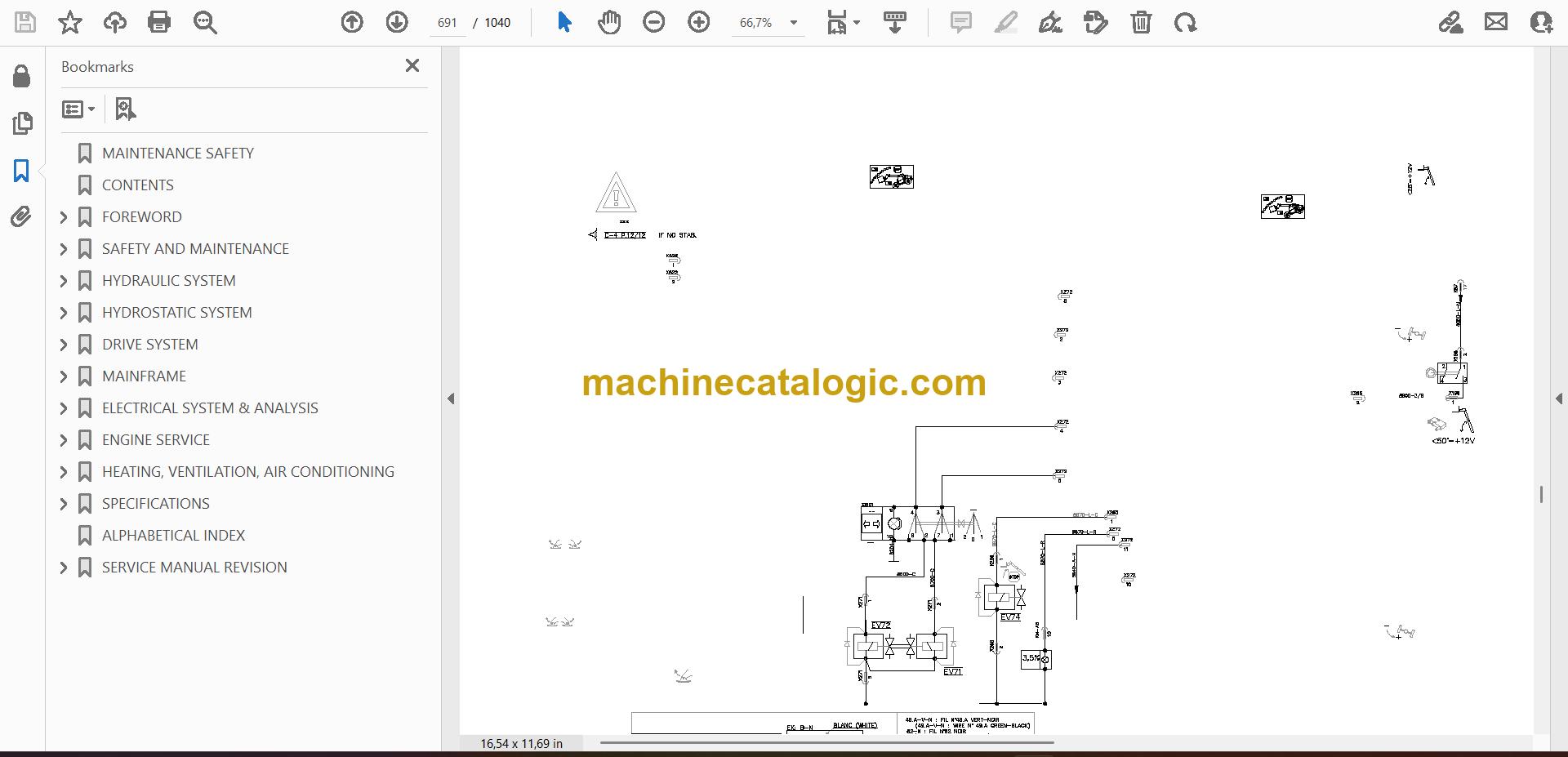
- Trace electrical faults with wiring diagrams so you can track down bad relays, sensors, or broken wires
- Follow teardown and reassembly procedures for major components like axles, boom sections, and hydraulic cylinders
- Check and set adjustments for linkages, brakes, and hydraulic functions after repairs
- Verify specs when you're doing engine, driveline, or hydrostatic system work so you don't guess on clearances or settings
Who this is for
This is for a small contractor, rental fleet, field tech, or owner-operator who is actually turning wrenches on a T35100 VersaHANDLER TTC in the A8HD11001-A8HD99999 serial range. If you only need operating tips or safety info, you want the operator's handbook instead, not this manual.
FAQ
Q: Is this a searchable PDF, and can I read the wiring diagrams?
A: These manuals are usually searchable PDFs and the wiring diagrams are meant to be zoomed in on a screen or printed.
Q: How do I know it fits my machine?
A: Check your serial number plate. If it starts with A8HD and falls between A8HD11001 and A8HD99999, this is the right one.
Q: Is this the right thing if I'm just doing basic maintenance?
A: If you're only changing fluids and filters, the operator's handbook is enough. This manual is for deeper troubleshooting and repair.
If your T35100's serial number lands in that A8HD range and you plan to do your own repairs, this is the right manual. If the serial doesn't match, don't buy it.
📘 Show Index
Table of Contents:
- MAINTENANCE SAFETY
- CONTENTS
- FOREWORD
- FOREWORD
- SAFETY INSTRUCTIONS
- FIRE PREVENTION
- Maintenance
- Operation
- Electrical
- Hydraulic System
- Fueling
- Starting
- Spark Arrestor Exhaust System
- Welding And Grinding
- Fire Extinguishers
- SERIAL NUMBER LOCATION
- Telescopic Handler Serial Number
- Engine Serial Number
- Other Serial Numbers
- DELIVERY REPORT
- BOBCAT TELESCOPIC HANDLER IDENTIFICATION
- SAFETY AND MAINTENANCE
- LIFTING AND BLOCKING THE TELESCOPIC HANDLER
- OPERATOR CAB (ROPS / FOPS)
- TRANSPORTING THE TELESCOPIC HANDLER ON A TRAILER
- Loading And Unloading
- Fastening
- TOWING THE TELESCOPIC HANDLER
- SERVICE SCHEDULE
- AIR CLEANER SERVICE
- Replacing Filter Element(s)
- ENGINE COOLING SYSTEM
- Cleaning
- Removing And Replacing The Coolant
- Checking Level
- FUEL SYSTEM
- Fuel Specifications
- Biodiesel Blend Fuel
- Filling The Fuel Tank
- Secondary Fuel Filter
- Primary Fuel Filter (Pre-Filter)
- Removing Air From The Fuel System
- ENGINE LUBRICATION SYSTEM
- Checking And Adding Engine Oil
- Engine Oil Chart
- Removing And Replacing Oil And Filter
- HYDRAULIC / HYDROSTATIC SYSTEM
- Checking And Adding Fluid
- Hydraulic / Hydrostatic Fluid Chart
- Removing And Replacing Hydraulic Fluid
- Removing And Replacing Hydraulic / Hydrostatic Filter
- Hydraulic Tank Breather
- AXLES (FRONT AND REAR)
- Checking And Adding Oil (Planetary Carrier)
- Removing And Replacing Oil (Planetary Carrier)
- Checking And Adding Oil (Rear Differential)
- Removing And Replacing Oil (Rear Differential)
- Checking And Adding Oil (Front Differential)
- Removing And Replacing Oil (Front Differential)
- Checking And Adding Oil (Front Drop Box)
- Removing And Replacing Oil (Front Drop Box)
- LUBRICATING THE TELESCOPIC HANDLER
- ATTACHMENT CARRIER
- Inspection And Maintenance
- TIRE MAINTENANCE
- Wheel Nuts
- Rotating
- Mounting
- APPROVED BOOM STOP
- Installing The Approved Boom Stop
- Removing The Approved Boom Stop
- ENGINE COVER
- CHAIN
- Checking And Adjustment Procedure
- Extend / Retract Chain Wear Check
- TELESCOPIC HANDLER STORAGE AND RETURN TO SERVICE
- Storage
- Return To Service
- STOPPING THE ENGINE AND LEAVING THE TELESCOPIC HANDLER
- EMERGENCY EXIT
- HYDRAULIC SYSTEM
- HYDRAULIC SCHEMATIC
- HYDRAULIC SYSTEM INFORMATION
- Glossary Of Hydraulic / Hydrostatic Symbols
- Troubleshooting Chart
- Tightening Procedures
- LIFT CYLINDER
- Removal And Installation
- Parts Identification
- Disassembly
- Assembly
- BUCKET POSITIONING CYLINDER
- Removal And Installation
- Parts Identification
- Disassembly
- Assembly
- EXTENSION CYLINDER
- Cylinder Group Removal And Installation
- Parts Identification
- Disassembly
- Assembly
- TILT CYLINDER
- Removal And Installation
- Parts Identification
- Disassembly
- Assembly
- STEERING CYLINDER (FRONT)
- Removing The Steering Cylinder
- Installing The Steering Cylinder
- Disassembling The Steering Cylinder
- Assembling The Steering Cylinder
- STEERING CYLINDER (REAR)
- Removing The Steering Cylinder
- Installing The Steering Cylinder
- Disassembling The Steering Cylinder
- Assembling The Steering Cylinder
- DRIVE BOX
- Parts Identification
- Disassembly
- Assembly
- Special Tools
- MAIN RELIEF VALVE
- Testing And Adjustment
- Removal And Installation
- QUICK-TACH CYLINDER
- Removal And Installation
- Parts Identification
- Disassembly
- Assembly
- FRAME LEVELING CYLINDER
- Removal And Installation
- Parts Identification
- Disassembly
- Assembly
- STEERING MODE VALVE BLOCK
- Removal And Installation
- Parts Identification
- Disassembly
- Solenoid Testing
- Assembly
- BRAKE VALVE
- Removal And Installation
- Disassembly And Assembly
- GEAR PUMP
- Removal And Installation
- Parts Identification
- Disassembly And Assembly
- FAN MOTOR
- Removal And Installation
- Parts Identification
- Disassembly And Assembly
- HYDRAULIC FLUID RESERVOIR
- STEERING VALVE
- Removal And Installation
- Parts Identification
- Disassembly
- Inspection
- Assembly
- HYDRAULIC CONTROL VALVE
- Troubleshooting Chart (Controllers)
- Telescoping Valve Section Troubleshooting
- Auxiliary Valve Section Troubleshooting
- Troubleshooting Chart (Control Valve)
- Removal And Installation
- Parts Identification
- Disassembly And Assembly
- End Housing Disassembly And Assembly
- Lifting Valve Section Disassembly And Assembly
- Tilting Valve Section Disassembly And Assembly
- Telescoping Valve Section Disassembly And Assembly
- Auxiliary / Frame Leveling Valve Section Disassembly And Assembly
- Inlet-Outlet Valve Section Disassembly And Assembly
- PORT RELIEF VALVES
- FLOW CONTROL VALVE
- JOYSTICK
- Removal And Installation
- PARKING BRAKE
- Parking Brake Valve Removal And Installation
- Parking Brake Valve Disassembly And Assembly
- Parking Brake Valve Disassembly And Assembly (Cont’d)
- PRESSURE REDUCING VALVE
- Testing
- Removal And Installation
- Disassembly And Assembly
- ACCUMULATOR
- TOW VALVE
- Removal And Installation
- Disassembly And Assembly
- STABILIZER CYLINDER (IF EQUIPPED)
- Removal
- Parts Identification
- Disassembly
- Assembly
- Installation
- STABILIZER CONTROL VALVE (IF EQUIPPED)
- Parts Identification
- Removal
- Installation
- HYDROSTATIC SYSTEM
- HYDROSTATIC SYSTEM INFORMATION
- Troubleshooting Chart
- Replenishing Valve Function
- OIL COOLER
- HYDROSTATIC DRIVE MOTOR
- Removal And Installation
- Parts Identification
- Disassembly
- Inspection
- Assembly
- HYDROSTATIC PUMP
- Removal And Installation
- Parts Identification
- Disassembly
- Inspection
- Assembly
- DRIVE SYSTEM
- TROUBLESHOOTING
- AXLE AND DIFFERENTIAL (FRONT)
- General Information
- Planetary Carrier Parts Identification
- Planetary Carrier Disassembly
- Steering Knuckle And Drive Axle Parts Identification
- Steering Knuckle Disassembly
- Drive Axle Disassembly
- Brake System Parts Identification
- Brake System Disassembly
- Differential Parts Identification
- Differential Disassembly
- Bevel Pinion Parts Identification
- Bevel Pinion Disassembly
- Bevel Pinion Assembly
- Differential Assembly
- Brake System Assembly
- Drive Axle Assembly
- Steering Knuckle Assembly
- Planetary Carrier Assembly
- Special Tools
- AXLE AND DIFFERENTIAL (REAR)
- General Information
- Planetary Carrier Parts Identification
- Steering Knuckle And Drive Axle Parts Identification
- Steering Knuckle Disassembly
- Differential And Bevel Pinion Parts Identification
- Differential Disassembly
- Bevel Pinion Disassembly
- Bevel Pinion Assembly
- Differential Assembly
- Steering Knuckle Assembly
- Planetary Carrier Assembly
- Special Tools
- FRONT AXLE
- AXLE TOE-IN
- PARKING BRAKE
- Releasing The Brake For Towing
- Re-Activating The Brake
- STEERING ANGLE ADJUSTMENT
- DRIVE SHAFT
- SERVICE BRAKE
- Description
- Bleeding The Brake Circuit
- REAR AXLE
- MAINFRAME
- OPERATOR CAB (S/N A8HD12999 & BELOW, S/N A8GW12999 & BELOW, S/N A8GT12999 & BELOW, S/ N A8GV12999 & BELOW, S/N A8GJ12999 & BELOW)
- OPERATOR CAB (S/N A8HD13000 & ABOVE, S/N A8GW13000 & ABOVE, S/N A8GT13000 & ABOVE, S/ N A8GV13000 & ABOVE, S/N A8GJ13000 & ABOVE)
- OPERATOR SEAT
- FIXED BOOM
- END BOOM
- WEAR PADS (FRONT)
- WEAR PADS (REAR)
- ENGINE COVER
- Gas Cylinder Removal And Installation
- Removal And Installation
- AIR INTAKE COWLING
- FUEL TANK
- QUICK-TACH
- REAR WEIGHTS
- FENDER
- PIVOT LINK
- JOYSTICK PANEL (S/N A8HD12999 & BELOW, S/N A8GW12999 & BELOW, S/N A8GT12999 & BELOW, S/ N A8GV12999 & BELOW, S/N A8GJ12999 & BELOW)
- JOYSTICK PANEL (S/N A8HD13000 & ABOVE, S/N A8GW13000 & ABOVE, S/N A8GT13000 & ABOVE, S/ N A8GV13000 & ABOVE, S/N A8GJ13000 & ABOVE)
- DASH COVER / STEERING COLUMN COVER (S/N A8HD12999 & BELOW, S/N A8GW12999 & BELOW, S/ N A8GT12999 & BELOW, S/NA8GV12999 & BELOW, S/N A8GJ12999 & BELOW)
- DASH COVER / STEERING COLUMN COVER (S/N A8HD13000 & ABOVE, S/N A8GW13000 & ABOVE, S/ N A8GT13000 & ABOVE, S/N A8GV13000 & ABOVE, S/N A8GJ13000 & ABOVE)
- INTERMEDIATE BOOM
- BOOM TRAY
- STABILIZER FRAME (IF EQUIPPED)
- ELECTRICAL SYSTEM & ANALYSIS
- ELECTRICAL SCHEMATIC
- ELECTRICAL SYSTEM INFORMATION (S/N A8HD12999 & BELOW, S/N A8GW12999 & BELOW, S/ N A8GT12999 & BELOW, S/N A8GV12999 & BELOW, S/N A8GJ12999 & BELOW)
- Troubleshooting Chart
- Description
- Fuses, Diode And Relay Location / Identification
- ELECTRICAL SYSTEM INFORMATION (S/N A8HD13000 & ABOVE, S/N A8GW13000 & ABOVE, S/ N A8GT13000 & ABOVE, S/N A8GV13000 & ABOVE, S/N A8GJ13000 & ABOVE)
- Troubleshooting Chart
- Description
- Fuses, Diode And Relay Location / Identification
- BATTERY
- Removal And Installation
- Servicing
- Using A Booster Battery (Jump Starting)
- ALTERNATOR
- Removal And Installation
- Belt Adjustment
- Belt Replacement
- STARTER
- Testing
- Removal And Installation
- LIGHTS
- Rear Light Removal And Installation
- Front Light Removal And Installation
- TRAVEL / SIGNAL LEVER (S/N A8HD12999 & BELOW, S/N A8GW12999 & BELOW, S/N A8GT12999 & BELOW, S/N A8GV12999 & BELOW, S/N A8GJ12999 & BELOW)
- TRAVEL / SIGNAL LEVER (S/N A8HD13000 & ABOVE, S/N A8GW13000 & ABOVE, S/N A8GT13000 & ABOVE, S/N A8GV13000 & ABOVE, S/N A8GJ13000 & ABOVE)
- INSTRUMENT PANEL
- SWITCH PANEL (S/N A8HD12999 & BELOW, S/N A8GW12999 & BELOW, S/N A8GT12999 & BELOW, S/ N A8GV12999 & BELOW, S/N A8GJ12999 & BELOW)
- Removal And Installation
- Parts Description
- SWITCH PANEL (S/N A8HD13000 – 14999, S/N A8GW13000 – 14999, S/N A8GT13000 – 14999, S/N A8GV13000 – 14999, S/N A8GJ13000 – 14999)
- SWITCH PANEL (S/N A8HD15000 & ABOVE, S/N A8GW15000 & ABOVE, S/N A8GT15000 & ABOVE, S/ N A8GV15000 & ABOVE, S/N A8GJ15000 & ABOVE)
- BRAKE LIGHT SWITCH
- Removal And Installation
- Adjustment
- WIPER MOTOR (Front)
- WIPER MOTOR (TOP)
- WIPER MOTOR (REAR)
- PEDAL ASSEMBLY
- INCHING SWITCH
- Removal And Installation
- Adjustment
- SERVICE SOFTWARE
- Connecting The Laptop Computer
- Entering The Service Software
- Monitor Screen
- Warnings Screen
- Calibrate Inch Pedal
- Calibrate Creep Potentiometer
- Program / Update Susmic Controller
- FRAME LEVEL SPEED SWITCH
- Description
- Removal
- Installation
- LONGITUDINAL STABILITY INDICATOR CALIBRATION (S/N A8HD11001-14999, S/N A8GW11001-14999, S/N A8GT11001-14999, S/N A8GV11001-14999, S/N A8GJ11001-14999)
- Fitting The Sensor
- Calibration Procedure
- LLMI / LLMC SYSTEM (S/N A8HD15000 & ABOVE, S/N A8GW15000 & ABOVE, S/N A8GT15000 & ABOVE, S/ N A8GV15000 & ABOVE, S/N A8GJ15000 & ABOVE)
- System Calibration
- Calibration Test
- System Failure Reports
- System Components Identification
- LLMS Removal
- LLMS Installation
- LLMC Controller Removal
- LLMC Controller Installation
- ENGINE SERVICE
- ENGINE INFORMATION
- Specifications
- Troubleshooting
- ENGINE SPEED CONTROL
- MUFFLER
- AIR CLEANER
- Housing Removal And Installation
- OIL COOLER / RADIATOR
- Removal And Installation
- Disassembly And Assembly
- ENGINE AND ENGINE MOUNTS
- ENGINE COMPONENTS AND TESTING
- Fuel Injection Pump Removal
- Fuel Injection Pump Installation
- Fuel Injectors Removal And Installation
- Checking The Fuel Lift Pump
- Fuel Lift Pump Removal And Installation
- Compression Checking
- Glow Plugs Checking
- Glow Plugs Removal And Installation
- ENGINE TIMING
- ENGINE / HYDROSTAT ASSEMBLY
- FLYWHEEL AND HOUSING
- Removal And Installation
- Ring Gear Removal
- Ring Gear Installation
- RECONDITIONING THE ENGINE
- Turbocharger Troubleshooting
- Turbocharger Description
- Turbocharger Removal And Installation
- Exhaust Manifold Removal And Installation
- Fuel Injector Cover Removal And Installation
- Rocker Cover Removal And Installation
- Cylinder Head Removal
- Cylinder Head Inspection
- Cylinder Head Installation
- Rocker Shaft Disassembly And Assembly
- Valve Removal
- Valve Springs Checking
- Valve Depth Checking
- Valve Guides Checking
- Valve Guide Removal
- Valve Guide Installation
- Valves Checking
- Cutting A Valve Seat
- Valve Seat Assembly
- Changing Valve Springs (With Cylinder Head Installed)
- Valve Clearance Adjustment
- Timing Case And Drive Assembly Description
- Timing Cover Removal
- Timing Cover Installation
- Crankshaft Pulley Removal And Installation
- Front Oil Seal Removal And Installation
- Timing Case And Gear Removal
- Timing Case And Gear Installation
- Camshaft And Tappets Removal
- Camshaft And Tappets Installation
- Pistons And Connecting Rods Description
- Pistons And Connecting Rods Removal
- Pistons And Connecting Rods Disassembly
- Piston Ring End Gap
- Piston Ring Installation
- Piston Ring Groove Clearance
- Connecting Rod Inspection
- Connecting Rod Bushing Replacement
- Piston And Connecting Rod Assembly
- Piston And Connecting Rod Installation
- Checking Piston Height
- Crankshaft And Bearings Description
- Crankshaft And Bearings Removal
- Inspection Of Crankshaft And Bearings
- Crankshaft And Bearings Installation
- Rear Oil Seal Removal
- Rear Oil Seal Housing Positioning
- Rear Oil Seal Installation
- Checking Crankshaft End Play
- Cooling System Description
- Thermostat Removal and Installation
- Thermostat Testing
- Lubricating Oil Cooler Removal And Installation
- Water Pump Removal
- Water Pump Installation
- Engine Lubrication System Description
- Oil Filter Adapter Removal And Installation
- Oil Pan Removal And Installation
- Oil Screen And Pick-up Tube
- Oil Pump Removal
- Oil Pump Installation
- Oil Pump Disassembly And Assembly
- Oil Pressure Relief Valve Disassembly And Assembly
- Engine Block Description
- Engine Block Disassembly And Assembly
- Piston Cooling Jet Removal
- Piston Cooling Jet Installation
- Piston Cooling Jet Alignment
- Inspection
- Cylinder Liner Inspection
- Cylinder Liner Removal
- Cylinder Liner Installation
- HEATING, VENTILATION, AIR CONDITIONING
- AIR CONDITIONING SYSTEM FLOW
- Description
- Chart
- Components
- Safety Equipment
- REGULAR MAINTENANCE
- Filters
- Compressor And Alternator Drive Belt Inspection
- Cleaning The Condenser
- Air Conditioning Lubrication
- Air Conditioning Service Chart
- TROUBLESHOOTING
- Blower Motor Does Not Operate
- Blower Motor Operates Normally, But Air Flow Is Insufficient
- Insufficient Cooling Although Air Flow And Compressor Operation Are Normal
- The Compressor Does Not Operate At All, Or Operates Improperly
- Gauge Pressure Related Troubleshooting
- Troubleshooting Tree
- Temperature / Pressure Chart
- Poor A/C Performance
- HVAC Repairs And Leaks
- Electrical System
- SYSTEM CHARGING AND RECLAMATION
- Reclamation Procedure
- Charging Procedure With A Manifold Gauge Set
- Charging Procedure
- COMPRESSOR
- Removal And Installation
- Oil
- Oil Check
- Clutch Disassembly And Assembly
- CONDENSER (S/N A8HD12999 & BELOW, A8GW12999 & BELOW, A8GT12999 & BELOW, A8GV12999 & BELOW, A8GJ12999 & BELOW)
- CONDENSER (S/N A8HD13000 & ABOVE, A8GW13000 & ABOVE, A8GT13000 & ABOVE, A8GV13000 & ABOVE, A8GJ13000 & ABOVE)
- RECEIVER / DRIER
- PRESSURE SWITCH
- EVAPORATOR / BLOWER UNIT (S/N A8HD12999 & BELOW, S/N A8GW12999 & BELOW, S/N A8GT12999 & BELOW, S/N A8GV12999 & BELOW, S/N A8GJ12999 & BELOW)
- EVAPORATOR / BLOWER UNIT (S/N A8HD13000 & ABOVE, A8GW13000 & ABOVE, A8GT13000 & ABOVE, A8GV13000 & ABOVE, A8GJ13000 & ABOVE)
- EXPANSION VALVE (S/N A8HD12999 & BELOW, A8GW12999 & BELOW, A8GT12999 & BELOW, A8GV12999 & BELOW, A8GJ12999 & BELOW)
- EXPANSION VALVE (S/N A8HD13000 & ABOVE, A8GW13000 & ABOVE, A8GT13000 & ABOVE, A8GV13000 & ABOVE, A8GJ13000 & ABOVE)
- HEATER ASSEMBLY
- Removal And Installation
- Fan Removal And Installation
- Core Removal And Installation
- SPECIFICATIONS
- (T35100) TELESCOPIC HANDLER SPECIFICATIONS
- Dimensional Specifications
- Performance Specifications
- Weights
- Engine
- Controls
- Drive System
- Traction
- Steering
- Brakes
- Fluid Capacities
- Hydraulic System
- Electrical
- Instruments
- Environmental
- Temperature Range
- (T35100L) TELESCOPIC HANDLER SPECIFICATIONS
- Dimensional Specifications
- Performance Specifications
- Weights
- Engine
- Controls
- Drive System
- Traction
- Steering
- Brakes
- Fluid Capacities
- Hydraulic System
- Electrical
- Instruments
- Environmental
- Temperature Range
- (T35100SL) TELESCOPIC HANDLER SPECIFICATIONS
- Dimensional Specifications
- Performance Specifications
- Weights
- Engine
- Controls
- Drive System
- Traction
- Steering
- Brakes
- Fluid Capacities
- Hydraulic System
- Electrical
- Instruments
- Environmental
- Temperature Range
- (T35120L) TELESCOPIC HANDLER SPECIFICATIONS
- Dimensional Specifications
- Performance Specifications
- Weights
- Engine
- Controls
- Drive System
- Traction
- Steering
- Brakes
- Fluid Capacities
- Hydraulic System
- Electrical
- Instruments
- Environmental
- Temperature Range
- (T35120SL) TELESCOPIC HANDLER SPECIFICATIONS
- Dimensional Specifications
- Performance Specifications
- Weights
- Engine
- Controls
- Drive System
- Traction
- Steering
- Brakes
- Fluid Capacities
- Hydraulic System
- Electrical
- Instruments
- Environmental
- Temperature Range
- MACHINE TORQUE SPECIFICATIONS
- Axle
- Boom
- Drive Box
- Drive Motor
- Engine
- Hydraulic Pump
- TORQUE SPECIFICATIONS FOR BOLTS
- Torque for General SAE Bolts
- Torque For General Metric Bolts
- HYDRAULIC CONNECTION SPECIFICATIONS
- O-ring Face Seal Connection
- Straight Thread O-ring Fitting
- Tubelines And Hoses
- Port Seal Fitting
- HYDRAULIC / HYDROSTATIC FLUID SPECIFICATIONS
- CONVERSIONS
- Decimal And Millimeter Equivalents
- U.S. To Metric Conversion
- ALPHABETICAL INDEX
- SERVICE MANUAL REVISION
- Revision No: T35100(S)(L), T35120(S)L – 2
- Revision No: T35100(S)(L), T35120(S)L – 3
Bobcat Software
Bobcat PDF Manuals


