The S130 is a small skid-steer loader that lives on driveways, barnyards, and tight jobsite corners, doing pallet work, grading, and cleanup. The people who grab this service manual are the ones actually turning wrenches: shop mechanics, field techs, and owner-operators who are done paying dealer rates. They want wiring diagrams that are readable, hydraulic specs, and step-by-step teardown so they can fix it once and not guess.
What this manual helps you do
- Diagnose hydraulic and hydrostatic issues, then check pressures and flows against Bobcat specs for this exact S130 serial range.
- Trace electrical faults using full wiring diagrams, then verify power, grounds, and sensor signals with a meter.
- Follow step-by-step procedures to remove, rebuild, and reinstall components like drive motors, cylinders, pumps, and Bob-Tach parts.
- Adjust linkages, controls, and safety interlocks so the loader drives straight, lifts square, and the seat bar and lockouts work correctly.
- Replace major assemblies, then set and verify things like belt tension, chain case setup, and control neutral positions.
Who this is for
This is for anyone working on a Bobcat S130 loader in the serial number range 527311001 through 527399999 who wants dealer-level repair info. If you only need basic controls, daily checks, and safety info, you want the operator's handbook instead, not this manual.
FAQ
Q: Is this a searchable PDF and are the wiring diagrams readable?
A: Yes, these manuals are normally supplied as searchable PDFs, and the wiring diagrams are clear enough to zoom in and trace circuits on a laptop or tablet.
Q: My S130 serial number is outside 527311001-527399999. Will this still work?
A: No, you really want the manual that matches your exact serial range, because Bobcat changes wiring, hydraulics, and some procedures between runs.
Q: I just bought a used S130 and plan to do my own repairs. Is this the right document?
A: Yes, this is the workshop service manual, the one you use for real repairs, not just operating tips or parts lookup.
Bottom line: If your S130 falls in that serial range and you're doing your own repairs, this is the correct service manual to buy.
📘 Show Index
Table of Contents:
- MAINTENANCE SAFETY
- ALPHABETICAL INDEX
- CONTENTS
- FOREWORD
- SAFETY INSTRUCTIONS
- SERIAL NUMBER LOCATIONS
- Loader Serial Number
- Engine Serial Number
- DELIVERY REPORT
- LOADER IDENTIFICATION
- SAFETY AND MAINTENANCE
- LIFTING AND BLOCKING THE LOADER
- LIFT ARM SUPPORT DEVICE
- Installing Lift Arm Support Device
- Removing The Lift Arm Support Device
- OPERATOR CAB
- Description
- Raising The Operator Cab
- Lowering The Operator Cab
- Emergency Exit
- TRANSPORTING THE BOBCAT LOADER
- TOWING THE LOADER
- REMOTE START
- SERVICE SCHEDULE
- AIR CLEANER SERVICE
- Checking
- Replacing Filter Element(s)
- ENGINE COOLING SYSTEM
- Cleaning The Cooling System
- Checking The Coolant Level
- Replacing The Coolant
- FUEL SYSTEM
- Fuel Specifications
- Filling the Fuel Tank
- Fuel Filter
- Removing Air From The Fuel System
- ENGINE LUBRICATION SYSTEM
- Checking Engine Oil
- Oil Chart
- Replacing Oil And Filter
- HYDRAULIC/HYDROSTATIC SYSTEM
- Checking And Adding Fluid
- Replacing Hydraulic/Hydrostatic Filter
- Replacing Hydrostatic Motor Case Drain Filter(s)
- Replacing Hydraulic Fluid
- Breather Cap
- FINAL DRIVE TRANSMISSION (CHAINCASE)
- Checking And Adding Oil
- Removing The Oil
- FAN GEARBOX
- BOB-TACH
- Inspection And Maintenance
- POWER BOB-TACH
- Inspection And Maintenance
- LUBRICATION OF THE BOBCAT LOADER
- TIRE MAINTENANCE
- Wheel Nuts
- Rotating
- Mounting
- SPARK ARRESTOR MUFFLER
- HYDRAULIC SYSTEM
- HYDRAULIC/HYDROSTATIC SCHEMATICS
- HYDRAULIC SYSTEM INFORMATION
- Glossary Of Hydraulic/Hydrostatic Symbols
- Tighten Procedures
- Troubleshooting Chart
- CYLINDER (LIFT)
- Checking
- Removal And Installation
- Identification
- Disassembly
- Assembly
- CYLINDER (TILT)
- Checking
- Removal And Installation
- Rod End Pivot Pin Bushing And Seal Replacement
- Identification
- Disassembly
- Assembly
- CYLINDER (POWER BOB-TACH)
- Checking
- Removal And Installation
- Parts Identification
- Disassembly
- Assembly
- MAIN RELIEF VALVE
- Checking
- Adjustment
- Removal and Installation
- HYDRAULIC CONTROL VALVE (FOOT CONTROL)
- Removal And Installation
- Identification Chart
- BICS™ Valve, Lift Load Check Valve Removal And Installation
- Load Check Valve Removal And Installation (Tilt & Auxiliary)
- Anti-Cavitation Valve (Lift, Rod End)
- Port Relief/Anti-Cavitation Valve (Lift, Base End)
- Port Relief/Anti-Cavitation Valve (Tilt, Base End)
- Port Relief/Anti-Cavitation Valve (Tilt, Rod End)
- Port Relief Valve
- Plug Removal
- Rubber Boot Removal and Installation
- End Cap/Spool Lock Block Removal and Installation
- Lift Spool and Detent Removal and Installation
- Tilt Spool Removal and Installation
- Auxiliary Spool Removal And Installation
- Auxiliary Solenoid Disassembly and Assembly
- BICS™ Valve Solenoid Disassembly And Assembly
- BICS™ Valve, Lock Valve Removal And Installation
- BICS™ Valve, Check Valve Removal And Installation
- BICS™ Valve, Lift Arm By-Pass Orifice Disassembly And Assembly
- Main Relief Valve
- HYDRAULIC CONTROL VALVE (ADVANCED CONTROL SYSTEM) (ACS)
- Removal And Installation
- Actuator Removal And Installation (Out of Loader)
- Identification Chart (ACS)
- BICS™ Valve, Lift Load Check Valve Removal And Installation
- Load Check Valve Removal And Installation (Tilt & Auxiliary)
- Anti-Cavitation Valve (Lift, Rod End)
- Port Relief/Anti-Cavitation Valve (Lift, Base End)
- Port Relief/Anti-Cavitation Valve (Tilt, Base End)
- Port Relief/Anti-Cavitation Valve (Tilt, Rod End)
- Port Relief Valve
- Plug Removal
- End Cap Block Removal and Installation
- Lift Spool Removal and Installation
- Tilt Spool Removal and Installation
- Auxiliary Spool Removal And Installation
- Auxiliary Solenoid Disassembly and Assembly
- BICS™ Valve Solenoid Disassembly And Assembly
- BICS™ Valve, Lock Valve Removal And Installation
- BICS™ Valve, Check Valve Removal And Installation
- BICS™ Valve, Lift Arm By-Pass Orifice Disassembly And Assembly
- Main Relief Valve
- LIFT ARM BY-PASS CONTROL VALVE
- Inspecting
- Removal And Installation
- Disassembly And Assembly
- HYDRAULIC PUMP
- Check The Output Of The Hydraulic Pump Without Rear Auxiliary
- Check The Output Of The Hydraulic Pump With Rear Auxiliary
- Removal And Installation
- Identification
- Disassembly And Assembly
- HYDRAULIC/HYDROSTATIC FILTER
- Housing Removal And Installation
- HYDRAULIC FLUID RESERVOIR
- BUCKET POSITION VALVE
- Solenoid Removal And Installation
- Solenoid Testing
- Removal And Installation
- Disassembly And Assembly
- REAR AUXILIARY DIVERTER VALVE
- Removal And Installation
- Disassembly And Assembly
- POWER BOB-TACH BLOCK
- Removal And Installation
- Disassembly And Assembly
- FRONT AUXILIARY HYDRAULIC COUPLER BLOCK
- Removal and Installation
- Disassembly And Assembly
- HYDROSTATIC SYSTEM
- HYDROSTATIC SYSTEM INFORMATION
- Troubleshooting Chart
- Replenishing Valve Function
- HYDROSTATIC MOTOR
- Removal And Installation
- Parts Identification
- Disassembly
- Assembly
- Carrier Shaft Seal Replacement
- Carrier Removal And Installation
- Carrier Parts Identification
- Carrier Disassembly
- Carrier Assembly
- CHARGE PRESSURE
- Sender Removal And Installation
- Checking Charge Pressure
- Adjusting
- HYDROSTATIC PUMP
- Replenishing/High Pressure Relief Valve
- Removal And Installation
- Parts Identification (Right Half)
- Parts Identification (Left Half)
- Hydraulic Pump Removal And Installation
- Pump Separation
- Disassembly
- Assembly
- DRIVE BELT
- Shield Removal And Installation
- Adjusting
- Drive Belt Replacement
- Tensioner Pulley Removal And Installation
- Tensioner Pulley Parts Identification
- Tensioner Pulley Disassembly
- Tensioner Pulley Assembly
- OIL COOLER
- DRIVE SYSTEM
- BRAKE
- Disc Removal And Installation
- Switch Operated Parking Brake
- DRIVE COMPONENTS
- Axle Seal Removal And Installation
- Axle Sprocket And Bearings Removal And Installation
- Chain Removal And Installation
- CHAINCASE
- Checking And Adding Oil
- Removing The Oil
- Front Cover Removal And Installation
- Center Cover Removal And Installation
- Rear Cover Removal And Installation
- MAIN FRAME
- SEAT BAR
- Removal And Installation
- Assembling Components
- Compression Spring Disassembly And Assembly
- OPERATOR CAB
- Gas Cylinder Removal And Installation
- Gas Cylinder Disassembly
- Removal And Installation
- OPERATOR SEAT
- Removal And Installation
- Seat Belt Removal And Installation
- OPERATOR SEAT (SUSPENSION)
- Removal And Installation
- Slide Rail Removal And Installation
- Cushion Removal And Installation
- Back Removal And Installation
- Shock Removal And Installation
- 3-Point Seat Belt Removal And Installation
- BOB-TACH
- Removal And Installation
- Bob-Tach Lever And Wedge
- Bob-Tach Stops
- POWER BOB-TACH
- Removal And Installation
- Power Bob-Tach Lever And Wedge
- LIFT ARM
- REAR GRILL
- REAR DOOR
- Removal And Installation
- Striker Removal and Installation
- Striker Disassembly and Assembly
- Door Latch and Catch Adjustment
- Latch Removal And Installation
- FUEL TANK
- Removal And Installation
- Fuel Level Sender
- CONTROL PEDALS
- Removal And Installation
- Pedal Adjustment
- Crossbar Linkage Removal And Installation
- Lift Foot Pedal Linkage Removal And Installation
- Tilt Foot Pedal Linkage Removal And Installation
- CONTROL PEDALS (ACS)
- Foot Sensor Removal And Installation
- Foot Pedal Removal And Installation
- Foot Pedal Linkage Disassembly And Assembly
- CONTROL PANEL
- Description
- Removal and Installation
- Shock Removal And Installation
- Shaft Removal And Installation
- Shaft Disassembly And Assembly
- Linkage Removal And Installation
- Pintle Arm Disassembly and Assembly
- Linkage Neutral Adjustment
- Linkage Travel Adjustment
- CONTROL HANDLE
- Control Lever Removal And Installation
- Control Rubber Boot Replacement
- CONTROL HANDLE (ADVANCED CONTROL SYSTEM) (ACS) SELECTABLE HAND/FOOT CONTROL
- Components Identification
- Handle Sensor Removal And Installation
- Control Handle Removal and Installation
- Control Handle Disassembly and Assembly
- Control Lever Removal and Installation
- Control Lever Boot
- ELECTRICAL SYSTEM & ANALYSIS
- ELECTRICAL SCHEMATIC
- ELECTRICAL SYSTEM INFORMATION
- Troubleshooting Chart
- Description
- Relay Switch Location
- Fuse Location
- Solenoid Test
- BATTERY
- Removal And Installation
- Servicing
- Using A Booster Battery (Jump Starting)
- ALTERNATOR
- Adjusting The Alternator Belt
- Alternator Identification
- Charging System Check
- Alternator Voltage Test
- Low Voltage Test
- High Voltage Test
- Removal And Installation
- Rectifier Continuity (Diode) Test
- Alternator Regulator Test
- Disassembly
- Stator Continuity Test
- Stator Ground Test
- Rotor Continuity Test
- Rotor Ground Test
- Assembly
- STARTER
- Checking
- Removal And Installation
- Parts Identification
- Disassembly and Assembly
- Inspection And Repair
- No Load Test
- INSTRUMENT PANEL
- Left Panel
- Right Panel (Standard) (With Key Switch)
- Right Panel – (Deluxe) (With Keyless Start)
- Right Panel Setup Display Options (Deluxe)
- Option and Field Accessory Panels
- Removal And Installation
- Front Accessory Panel Removal And Installation
- LIGHTS
- Front Removal And Installation
- Rear Removal And Installation
- BOBCAT CONTROLLER
- Identification Chart
- Removal And Installation
- DIAGNOSTIC SERVICE CODES
- Display
- Number Codes List
- BICS™ SYSTEM
- Inspecting The BICS™ Controller (Engine STOPPED – Key ON)
- Inspecting Deactivation Of The Auxiliary Hydraulics System (Engine STOPPED – Key ON)
- Inspecting The Seat Bar Sensor (Engine RUNNING)
- Inspecting The Traction Lock (Engine RUNNING)
- Inspecting The Lift Arm By-Pass Control
- Additional Inspection For Loaders With Advanced Controls System (ACS) or Selectable Joystick Control (SJC)
- Troubleshooting Chart
- Troubleshooting Guide
- SEAT BAR SENSOR
- Troubleshooting Chart
- Test
- Removal And Installation
- BICS™ Circuit Test
- TRACTION LOCK
- Troubleshooting Chart
- Inspecting
- Solenoid Removal And Installation
- Guide Removal
- Guide Installation
- ADVANCED CONTROL SYSTEM (ACS) SELECTABLE HAND/FOOT CONTROL
- Components Identification
- Troubleshooting Guide
- Controller, Connector And Wire Identification
- ACS Controller Removal And Installation
- Handle Sensor Connector
- Switch Handle Removal
- Switch Handle Installation
- Actuators Disassembly And Assembly
- Handle Lock Solenoid Removal And Installation
- Handle Lock Solenoid Disassembly And Assembly
- Handle Lock Solenoid Connector
- Calibration Of The ACS System
- Switchable Hand/Foot Controls Calibration Procedure
- Foot Sensor Disassembly And Assembly
- Foot Sensor Connector
- Foot Lock Solenoid Removal And Installation
- Foot Lock Solenoid Connector
- ELECTRICAL/HYDRAULIC CONTROLS REFERENCE
- Controls Identification Chart
- FLYWHEEL RPM SENSOR
- ENGINE SERVICE
- TROUBLESHOOTING
- ENGINE SPEED CONTROL
- Removal And Installation
- Disassembly
- MUFFLER
- AIR CLEANER
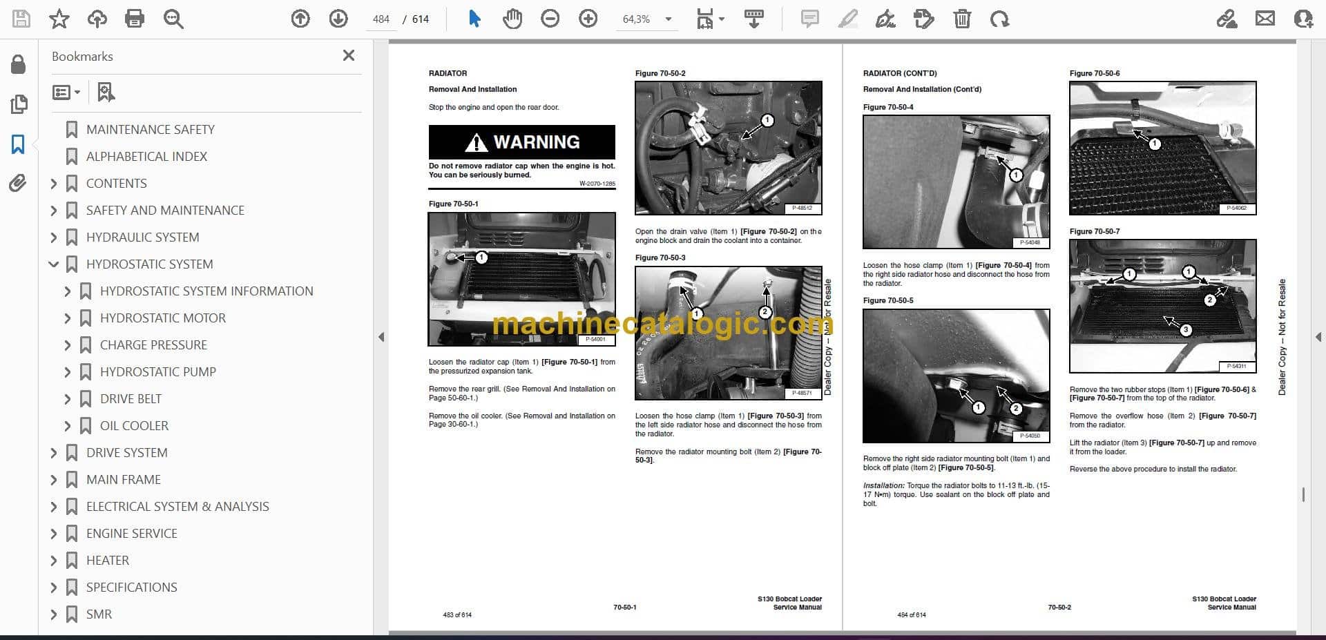
- RADIATOR
- COOLING FAN
- Drive Tension Pulley Removal And Installation
- Gearbox/Blower Housing Removal And Installation
- Blower Housing Grill Removal And Installation
- Blower Disassembly And Assembly
- Gearbox Parts Identification
- Gearbox Disassembly
- Gearbox Assembly
- Gearbox Checking Backlash
- ENGINE COMPONENTS AND TESTING
- Compression Checking
- Glow Plugs Checking
- Glow Plugs Removal And Installation
- Fuel Shut-Off Solenoid, Checking
- Fuel Shut-Off Solenoid Removal And Installation
- Fuel Injection Pump Removal And Installation
- Timing The Injection Pump
- Fuel Injector Removal And Installation
- Checking Nozzle Injection Pressure
- Nozzle Spraying Condition
- Valve Seat Tightness
- Valve Clearance Adjustment
- Valve Timing, Checking
- ENGINE
- Removal And Installation
- Engine Mount Replacement
- FLYWHEEL AND HOUSING
- Flywheel Removal And Installation
- Ring Gear Removal And Installation
- Housing Removal And Installation
- RECONDITIONING THE ENGINE
- Cylinder Head Removal And Installation
- Cylinder Head Disassembly And Assembly
- Cylinder Head Servicing
- Cylinder Head Top Clearance
- Valve Guide Checking
- Reconditioning The Valve And Valve Seat
- Valve Spring
- Rocker Arm And Shaft Checking
- Timing Gearcase Cover Removal And Installation
- Idler Gear And Camshaft Removal And Installation
- Camshaft Servicing
- Idler Gear And Shaft Servicing
- Timing Gears Checking Backlash
- Fuel Camshaft Removal And Installation
- Fuel Camshaft Governor
- Crankshaft Gear Removal And Installation
- Oil Pump Removal And Installation
- Oil Pump Service
- Checking Engine Oil Pressure
- Valve Tappets
- Piston And Connecting Rod Removal And Installation
- Piston And Connecting Rod Servicing
- Connecting Rod Alignment
- Crankshaft And Bearings Removal And Installation
- Crankshaft And Bearings, Servicing
- Cylinder Bore, Checking
- Water Pump Removal And Installation
- Water Pump Disassembly And Assembly
- HEATER
- COMPONENTS
- REGULAR MAINTENANCE
- Filter Elements Removal And Installation
- BASIC TROUBLESHOOTING
- Cleaning The Heater Coil
- Checking The Electrical System
- Engine Coolant By-Passing The Heater Valve
- Heater Valve Not Opening Or Closing
- SYSTEM TROUBLESHOOTING CHART
- Blower Motor Does Not Operate
- Blower motor operators normally, but air flow is insufficient
- HEATER UNIT
- Removal And Installation
- Disassembly And Assembly
- HEATER COIL
- HEATER FAN
- Removal And Installation
- Disassembly And Assembly
- Wire Connector Removal and Installation
- HEATER VALVE
- Removal and Installation
- Disassembly And Assembly
- SPECIFICATIONS
- LOADER SPECIFICATIONS (S130)
- Machine Dimensions
- Performance
- Controls
- Engine
- Hydraulic System
- Electrical
- Drive System
- Capacities
- Tires
- ENGINE SPECIFICATIONS
- Fuel Injection Nozzles
- Fuel Injection Pump
- Cylinder Head
- Valves
- Valve Springs
- Valve Timing
- Rocker Arms
- Camshaft
- Tappet
- Cylinders
- Piston Rings
- Pistons
- Connecting Rod
- Oil Pump
- Crankshaft
- Timing Gear
- Thermostat
- TORQUE SPECIFICATIONS FOR BOLTS
- Torque For General SAE Bolts
- Torque For General Metric Bolts
- Torque For Kubota Metric Bolts
- HYDRAULIC CONNECTION SPECIFICATIONS
- O-ring Face Seal Connection
- Straight Thread O-ring Fitting
- Tubelines And Hoses
- Flare Fitting
- O-ring Flare Fitting
- Port Seal Fitting
- HYDRAULIC FLUID SPECIFICATIONS
- CONVERSIONS
- Decimal And Millimeter Equivalents
- U.S. To Metric Conversion
- SMR
Bobcat Software
Bobcat PDF Manuals