On a job, a Bobcat 430 mini excavator is your trenching, footing, and utility machine, squeezing into spots a backhoe won't. Folks grab the service manual when the 430 is out of warranty, something's leaking or dead, and downtime is killing the day's profit. Around my shop, this is what I pull when I'm chasing a hydraulic issue, doing engine work, or sorting out a wiring gremlin. You're not looking for sales fluff here, you're looking for how it actually comes apart and goes back together.
What this manual helps you do
- Diagnose hydraulic problems on the 430's boom, arm, bucket, and auxiliary circuits using pressure checks and step-by-step tests
- Trace and repair electrical faults with wiring diagrams and connector pinouts for this exact 430 series
- Follow teardown and reassembly procedures on the engine, pumps, drive motors, and swing components
- Check and set adjustments on controls, pilot lines, track drives, and swing so the machine runs straight and smooth
- Replace seals, hoses, and wear parts with the right sequence and torque references so you only do the job once
Who this is for
This is for someone working on a Bobcat 430 excavator with serial number AACF11001 through AACF99999 who actually turns wrenches: small contractor, owner-operator, shop mechanic, or rental fleet tech. If you just need operating tips, safety, or basic maintenance intervals, you want the operator's handbook instead, not this service manual.
FAQ
Q: Is this a searchable PDF and are the wiring diagrams readable?
A: Yes, these manuals are usually in searchable PDF and the wiring diagrams are clear enough to zoom in and follow circuits.
Q: How do I know if it covers my exact 430?
A: Check your machine's serial plate. If it falls between AACF11001 and AACF99999, this is the right manual.
Q: Is this what I need for real repairs, not just fluids and filters?
A: Yes, this is the workshop-level service manual, meant for full diagnostics and repair, not basic daily maintenance.
Bottom line: If your 430's serial number is in that AACF range and you're doing your own repairs, this is the manual you want. If your serial doesn't match, skip it.
📘 Show Index
Table of Contents:
- MAINTENANCE SAFETY
- CONTENTS
- FOREWORD
- FOREWORD
- SAFETY INSTRUCTIONS
- FIRE PREVENTION
- Maintenance
- Operation
- Electrical
- Hydraulic System
- Fueling
- Starting
- Spark Arrester Exhaust System
- Welding And Grinding
- Fire Extinguishers
- SERIAL NUMBER LOCATIONS
- Excavator Serial Number
- Engine Serial Number
- DELIVERY REPORT
- BOBCAT EXCAVATOR IDENTIFICATION
- SAFETY AND MAINTENANCE
- LIFTING AND BLOCKING THE EXCAVATOR
- UPPERSTRUCTURE SLEW LOCK
- LIFTING THE EXCAVATOR
- OPERATOR CAB (ROPS / TOPS)
- Description
- Cab Door
- Front Window
- Front Wiper
- Window Washer Reservoir
- Right Side Window
- Heating, Ventilation, And Air Conditioning Duct
- TRANSPORTING THE EXCAVATOR ON A TRAILER
- Loading And Unloading
- Fastening
- TAILGATE
- Opening And Closing The Tailgate
- Adjusting The Latch
- RIGHT SIDE COVER
- Opening And Closing The Right Side Cover
- SERVICE SCHEDULE
- AIR CLEANER
- Daily Check
- Replacing The Elements
- HEATER AIR FILTER (WITH CAB OPTION ONLY)
- ENGINE COOLING SYSTEM
- Cleaning The Cooling System
- Checking Coolant Level
- Removing And Replacing Coolant
- FUEL SYSTEM
- Fuel Specifications
- Biodiesel Blend Fuel
- Filling The Fuel Tank
- Removing Water
- Replacing Element
- Draining The Fuel Tank
- Inline Fuel Filter
- Removing Air From The Fuel System
- ENGINE LUBRICATION SYSTEM
- Checking And Adding Engine Oil
- Engine Oil Chart
- Removing And Replacing Oil And Filter
- HYDRAULIC SYSTEM
- Checking And Adding Fluid
- Hydraulic Fluid Chart
- Removing And Replacing The Hydraulic Fluid
- Removing And Replacing The Hydraulic Filter
- Removing And Replacing The Case Drain Filter
- Removing And Replacing The Fan Filter
- Diagnostic Couplers
- LUBRICATNG THE EXCAVATOR
- TRAVEL MOTOR
- Checking And Adding Oil
- Removing And Replacing Oil
- SPARK ARRESTER MUFFLER
- ALTERNATOR BELT
- Belt Tension
- Belt Adjustment
- SEAT BELT
- Inspection And Maintenance
- PIVOT PINS
- Inspection And Maintenance
- EXCAVATOR STORAGE AND RETURN TO SERVICE
- Storage
- Return To Service
- STOPPING THE ENGINE AND LEAVING THE EXCAVATOR
- Procedure
- Emergency Exits
- MOTION ALARM SYSTEM
- Description
- Inspecting
- Adjusting Switch Position
- HYDRAULIC SYSTEM
- HYDRAULIC / HYDROSTATIC SCHEMATICS
- HYDRAULIC SYSTEM INFORMATION
- Glossary Of Hydraulic / Hydrostatic Symbols
- Troubleshooting The Hydraulic Circuit
- Troubleshooting The Cylinder Circuit
- Troubleshooting The Swing (Upperstructure Slew) Circuit
- Troubleshooting The Travel Circuit
- CYLINDER (BOOM)
- Testing
- Removal And Installation
- Parts Identification
- Disassembly
- Assembly
- CYLINDER (ARM)
- Testing
- Removal And Installation
- Parts Identification
- Disassembly
- Assembly
- CYLINDER (BOOM SWING)
- Testing
- Removal And Installation
- Parts Identification
- Disassembly
- Assembly
- CYLINDER (BUCKET)
- Testing
- Removal And Installation
- Parts Identification
- Disassembly
- Assembly
- CYLINDER (BLADE)
- Testing
- Removal And Installation
- Parts Identification
- Disassembly
- Assembly
- CYLINDER (CLAMP)
- Testing
- Removal And Installation
- Parts Identification
- Disassembly
- Assembly
- CYLINDER (ANGLE BLADE)
- Testing
- Removal And Installation
- Parts Identification
- Disassembly
- Assembly
- CYLINDER (EXTENDIBLE ARM)
- Removal And Installation
- Parts Identification
- Disassembly
- Assembly
- VALVES (MAIN RELIEF)
- Testing And Adjusting The Main Relief Valves (S/N AACF11001 & Above And AA8711001 & Above)
- System Pressures At Gauge Port Specifications
- Testing And Adjusting The Main Relief Valves (S/N AACG11001 & Above And AA8811001 & Above)
- System Pressures At Gauge Port Specifications
- VALVES (PORT RELIEF)
- Testing And Adjusting Port Relief Valve Pressure
- VALVES (CROSSPORT RELIEF)
- Testing And Adjusting The Crossport Relief Valves (S/N AACF11001 & Above And AA8711001 & Above)
- Testing And Adjusting The Crossport Relief Valves (S/N AACG11001 & Above And AA8811001 & Above)
- VALVE (PRESSURE REDUCING)
- VALVE (ANGLE BLADE)
- Description
- Testing And Adjusting Port Relief Valves
- Testing And Adjusting Sequence Valve
- Removal And Installation
- Parts Identification
- Disassembly
- Assembly
- HYDRAULIC CONTROL VALVE (S/N AACF11001 & ABOVE AND AA8711001 & ABOVE)
- Description
- Removal And Installation
- Parts Identification
- Disassembly
- Right Travel Valve Section Disassembly And Assembly
- Left Travel Valve Section Disassembly And Assembly
- Blade Valve Section Disassembly And Assembly
- Slew Valve Section Disassembly And Assembly
- Auxiliary Valve Section Disassembly And Assembly
- Bucket Valve Section Disassembly And Assembly
- Arm Valve Section Disassembly And Assembly
- Boom Valve Section Disassembly And Assembly
- Boom Swing Valve Section Disassembly And Assembly
- Inlet Section Disassembly And Assembly
- Assembly
- HYDRAULIC CONTROL VALVE (S/N AACG11001 & ABOVE AND AA8811001 & ABOVE)
- Description
- Removal And Installation
- Parts Identification
- Disassembly
- Blade Valve Section Disassembly And Assembly
- Slew Valve Section Disassembly And Assembly
- Auxiliary Valve Section Disassembly And Assembly
- Bucket Valve Section Disassembly And Assembly
- Arm Valve Section Disassembly And Assembly
- Boom Valve Section Disassembly And Assembly
- Boom Swing Valve Section Disassembly And Assembly
- Inlet Section Disassembly And Assembly
- Assembly
- HYDRAULIC PUMP
- Description
- Torque Adjustment
- Testing The Piston Pump
- Testing The Gear Pump
- Testing Auxiliary Flow
- Removal And Installation
- Coupler Removal And Installation
- Hydraulic Pump Start Up
- Gear Pump Parts Identification
- Piston Pump Parts Identification
- Disassembly
- Gear Pump Disassembly
- Gear Pump Assembly
- Piston Pump Disassembly
- Piston Pump Assembly
- Assembly
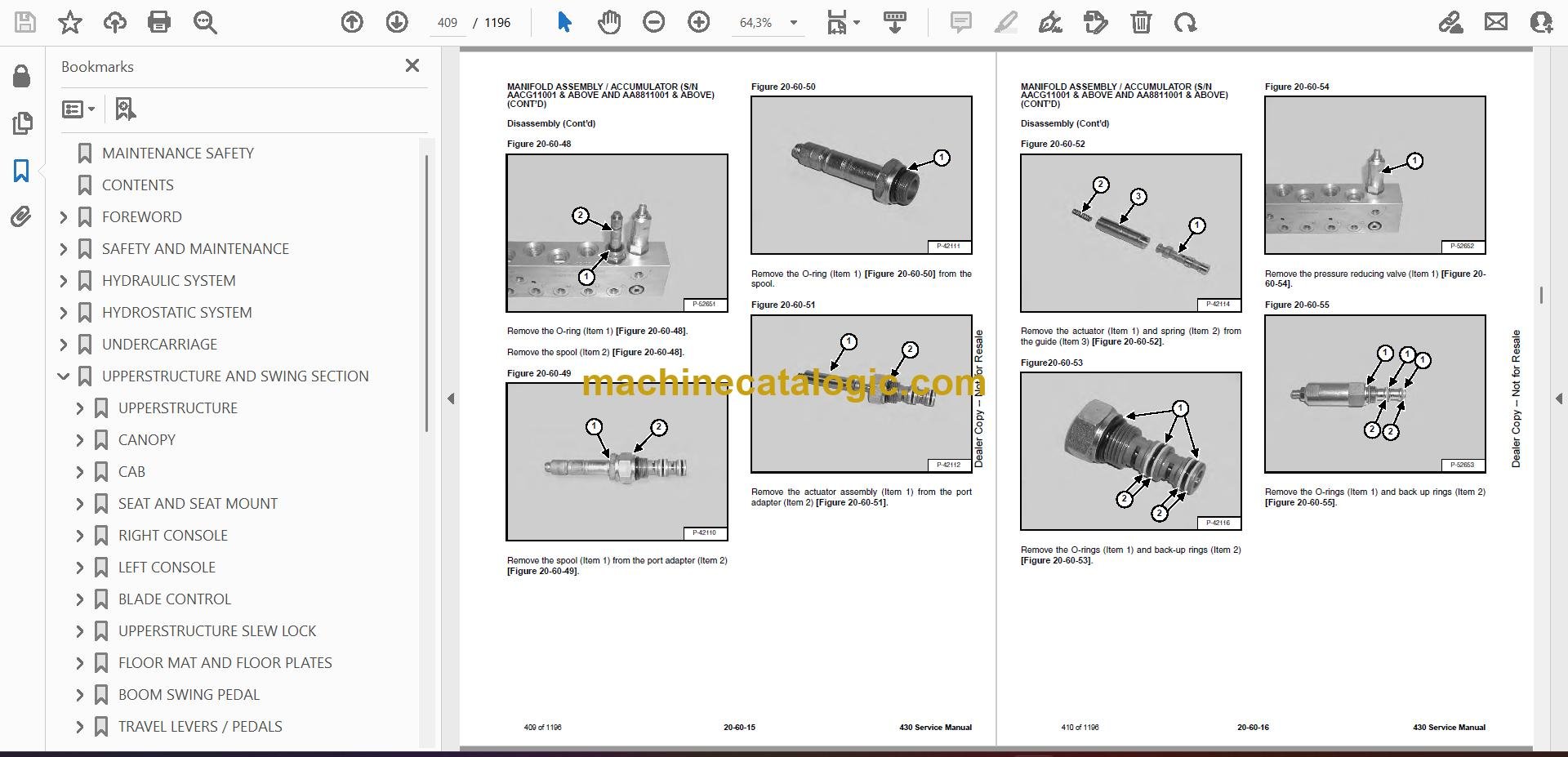
- MANIFOLD ASSEMBLY / ACCUMULATOR (S/N AACG11001 & ABOVE AND AA8811001 & ABOVE)
- Description
- Testing Pilot Pressure
- Removal And Installation
- Parts Identification
- Disassembly
- Assembly
- MANIFOLD ASSEMBLY / ACCUMULATOR (S/N AACF11001 & ABOVE AND AA8711001 & ABOVE)
- Description
- Testing Pilot Pressure
- Removal And Installation
- Parts Identification
- Disassembly
- Assembly
- TRAVEL MOTOR (S/N AACG11001 & ABOVE AND AA8811001)
- Description
- Removal And Installation
- Parts Identification
- Disassembly
- Assembly
- TRAVEL MOTOR (S/N AACF11001 & ABOVE AND AA8711001 & ABOVE)
- Description
- Removal And Installation
- Parts Identification
- Disassembly
- Assembly
- SWIVEL JOINT
- Removal And Installation
- Parts Identification
- Description
- Disassembly
- Assembly
- SWING MOTOR
- Description
- Removal And Installation
- Parts Identification
- Disassembly
- Assembly
- SWING MOTOR (DRIVE CARRIER)
- Description
- Removal And Installation
- Parts Identification
- Disassembly
- Assembly
- CONTROL PATTERN SELECTOR VALVE
- Description
- Removal And Installation
- Parts Identification
- Disassembly
- Assembly
- RIGHT CONTROL LEVER (JOYSTICK)
- Description
- Testing
- Handle Removal And Installation
- Joystick Assembly Removal And Installation
- Parts Identification
- Disassembly
- Assembly
- LEFT CONTROL LEVER (JOYSTICK)
- Description
- Testing
- Handle Removal And Installation
- Joystick Assembly Removal And Installation
- Parts Identification
- Disassembly
- Assembly
- TRAVEL CONTROL VALVE (S/N AACG11001 & ABOVE AND AA8811001 & ABOVE)
- Removal and Installation
- Parts Identification
- Disassembly And Assembly
- TRAVEL CONTROL VALVE (S/N AACF11001 & ABOVE AND AA8711001 & ABOVE)
- Removal and Installation
- Parts Identification
- Disassembly And Assembly
- HOSES
- Hose Guide Location
- Left Control Lever (Joystick) (S/N AACF11001 & Above AND AA8711001 & Above)
- Left Control Lever (Joystick) (S/N AACG11001 AND AA8811001 & Above)
- Right Control Lever (Joystick) (S/N AACF11001 And Above AA8711001 & Above)
- Right Control Lever (Joystick) (S/N AACG11001 & Above And AA8811001 & Above)
- Travel Control Valve (S/N AACF11001 & Above And AA8711001 & Above)
- Travel Control Valve (S/N AACG11001 & Above And AA8811001 & Above)
- Manifold Assembly / Accumulator (S/N AACF11001 & Above And AA8711001 & Above)
- Manifold Assembly / Accumulator (S/N AACG11001 & Above And AA8811001 & Above)
- HYDRAULIC FILTER
- Description
- Housing Removal And Installation
- CASE DRAIN FILTER
- HYDRAULIC RESERVOIR
- Description
- Removal And Installation
- OIL COOLER
- Description
- Removal And Installation
- DIRECT TO TANK VALVE
- Description
- Removal And Installation
- Parts Identification
- Disassembly And Assembly
- BUILD UP VALVE
- COOLING FAN
- Description
- Testing
- Removal And Installation
- Parts Identification
- Disassembly And Assembly
- BOOM SWING LOCK VALVE
- Description
- Removal And Installation
- Parts Identification
- Disassembly
- Assembly
- HYDRAULIC X-CHANGE™ VALVE
- Removal And Installation
- Parts Identification
- Disassembly
- Assembly
- SLEW LOCK VALVE
- Description
- Removal And Installation
- Parts Identification
- Disassembly And Assembly
- HYDROSTATIC SYSTEM
- HYDROSTATIC SYSTEM INFORMATION
- Troubleshooting Chart
- Relief / Replenishing Valve Function
- Relief / Replenishing Valve Location
- Relief / Replenishing Valve Removal And Installation
- Charge Pressure Relief Valve Location
- Charge Pressure Relief Valve Removal And Installation
- TRAVEL PILOT PRESSURE
- HYDROSTATIC PUMP
- Removal And Installation
- Parts Identification (Front) (S/N AACG11001 & Above And AA8811001 & Above)
- Disassembly
- Inspection
- Assembly
- Hydrostatic Pump Start-Up
- Mechanical Neutral Adjustment
- DRIVE BELT SHIELD
- DRIVE BELT
- Adjustment
- Removal And Installation
- UNDERCARRIAGE
- BLADE
- ANGLE BLADE ASSEMBLY
- ANGLE BLADE
- ANGLE BLADE CUTTING EDGE
- TRACK FRAME COMPONENTS
- Description
- Track Lug Height
- Checking Tension
- Adjusting Tension
- Rubber Track Removal And Installation
- Steel Track Removal And Installation
- Idler (Front) Removal And Installation
- Idler (Front) Parts Identification
- Idler (Front) Disassembly
- Idler (Front) Assembly
- Coil Spring Assembly And Cylinder (S/N AACF11246 & Below, AACG11102 & Below, AA8711102 & Below And AA8811101 & Below)
- Coil Spring Cylinder Parts Identification (S/N AACF11247 & Above, AACG11103 & Above, AA8711103 & Above And AA8811102 & Above)
- Coil Spring Cylinder Disassembly And Assembly (S/ N AACF11247 & Above, AACG11103 & Above, AA8711103 & Above And AA8811102 & Above)
- Roller Removal And Installation
- Roller Parts Identification
- Roller Disassembly
- Roller Assembly
- Track Damage Identification
- Abrasion Of Embedded Metals
- SWING CIRCLE GEAR
- Swing Bearing Removal
- Swing Bearing Installation
- UPPERSTRUCTURE AND SWING SECTION
- UPPERSTRUCTURE
- Description
- Removal
- Installation
- CANOPY
- CAB
- Removal And Installation
- Door Removal And Installation
- Front Window Removal And Installation
- Right Side Rear Sliding Window Removal And Installation
- Right Side Front Sliding Window Removal And Installation
- Glass Removal
- Right Side Front And Rear Sliding Window Weather Strip Removal And Installation
- Right Side Front And Rear Sliding Window Wiper Strip Removal And Installation
- Glass Installation
- SEAT AND SEAT MOUNT
- Seat Mount Removal And Installation
- Seat Removal And Installation
- RIGHT CONSOLE
- Description
- Console Cover Removal And Installation
- Console Frame Removal And Installation
- LEFT CONSOLE
- Description
- Joystick Console Cover (Bottom) Removal And Installation
- Joystick Console Cover (Top) Removal And Installation
- Compression Spring Removal And Installation
- Compression Spring Disassembly And Assembly
- Lever Removal And Installation
- Joystick Console Frame Removal And Installation
- Joystick Console Frame Disassembly And Assembly
- Left Rear Console Cover Removal And Installation
- Left Rear Console Frame Removal And Installation
- BLADE CONTROL
- Removal And Installation
- Linkage Removal And Installation
- Linkage Disassembly And Assembly
- Control Cable Removal And Installation
- UPPERSTRUCTURE SLEW LOCK
- Removal And Installation
- Disassembly And Assembly
- FLOOR MAT AND FLOOR PLATES
- Description
- Removal And Installation
- BOOM SWING PEDAL
- Description
- Pedal Removal And Installation
- Pedal Disassembly And Assembly
- Control Cable Removal And Installation
- TRAVEL LEVERS / PEDALS
- Description
- Adjustment
- Removal And Installation
- Disassembly And Assembly
- Control Linkage Assembly Removal And Installation
- FUEL TANK
- HORN
- SWING FRAME
- Description
- Removal And Installation
- Hose Routing
- Bushing Removal
- Bushing Installation
- BOOM
- Description
- Removal And Installation
- ARM
- Description
- Removal And Installation
- Arm To Boom Bushing Removal And Installation
- Arm To Bucket And Bucket Link Bushing Removal And Installation
- BUCKET
- Removal And Installation (Pin-On X-Change™)
- Removal And Installation (Bolt-On X-Change™)
- Removal And Installation (Pin-On Attachment)
- Removal And Installation (Hydraulic X-Change™)
- Bucket Teeth Removal And Installation
- Bucket Side Cutting Edge Removal And Installation
- CLAMP
- TAILGATE
- X-CHANGE™
- Removal And Installation
- Parts Identification
- Disassembly
- Assembly
- Check Proper Latch Engagement
- X-CHANGE™ (HYDRAULIC)
- Removal And Installation
- Parts Identification
- Disassembly
- Assembly
- RIGHT SIDE COVER
- COUNTERWEIGHT
- QUICK COUPLER (KLAC™ SYSTEM)
- Troubleshooting
- Daily Inspection
- Removal And Installation
- Parts Identification
- Disassembly
- Assembly
- QUICK COUPLER (LEHNHOFF® SYSTEM)
- Troubleshooting
- Daily Inspection
- Removal (MS03 And MS08)
- Installation (MS03 And MS08)
- Parts Identification (MS03)
- Disassembly And Assembly (MS03)
- Parts Identification (MS08)
- Disassembly (MS08)
- Assembly (MS08)
- ELECTRICAL SYSTEM AND ANALYSIS
- ELECTRICAL SCHEMATICS
- ELECTRICAL SYSTEM INFORMATION
- Troubleshooting Chart
- Description
- Fuse And Relay Location
- BATTERY
- Removing And Installing The Battery
- Servicing
- Using A Booster Battery (Jump Starting)
- ALTERNATOR
- Belt Adjustment
- Belt Replacement
- Charging System Inspection
- Alternator Description
- High Voltage Test
- Rectifier Continuity (Diode) Test
- Alternator Voltage Test
- Low Voltage Test
- Alternator Regulator Test
- Parts Identification
- Disassembly
- Stator Continuity Test
- Stator Ground Test
- Rotor Continuity Test
- Rotor Ground Test
- Assembly
- Removal And Installation
- STARTER
- Testing
- Removal And Installation
- Parts Identification
- Disassembly
- Inspection And Repair
- Assembly
- LIGHTS
- Upperstructure Light Removal And Installation
- Upperstructure Light Disassembly And Assembly
- Boom Light Removal And Installation
- Boom Light Bulb Replacement
- MAGNETIC LOCKOUT SENSOR
- Testing Left Console Magnetic Lockout Sensor
- Console Switch Removal And Installation
- FUEL LEVEL SENDER
- Removal And Installation
- Testing
- DIAGNOSTICS SERVICE CODES
- DELUXE INSTRUMENT PANEL SETUP
- Passwords
- Password Entry (For Starting And Operating The Machine)
- Changing The Owner or Operator Password
- Password Lockout Feature
- Job Clock
- RPM
- TWO-SPEED SWITCH
- ENGINE SERVICE
- ENGINE INFORMATION
- Description
- Specifications
- Torque Values
- Troubleshooting Chart
- Removal And Installation
- Compression Checking
- ENGINE SPEED CONTROL
- Removal And Installation
- Disassembly And Assembly
- Adjustment (S/N AA8711001 & Above And AA8811001 & Above)
- SPARK ARRESTER MUFFLER
- AIR CLEANER
- ENGINE COOLING SYSTEM
- Radiator Removal And Installation
- Testing The Thermostat
- Thermostat Housing Removal And Installation
- Water Pump Removal And Installation
- Water Pump Disassembly And Assembly
- LUBRICATION SYSTEM
- Oil Pan Removal And Installation
- Oil Pump Removal And Installation
- Oil Pump Inspection
- Engine Oil Pressure – Testing
- FUEL SYSTEM
- Fuel Camshaft Removal And Installation
- Fuel Camshaft Governor Disassembly And Assembly
- Fuel ShutOff Solenoid – Checking
- Fuel Shut-off Solenoid Removal And Installation
- Fuel Injection Pump Removal And Installation
- Injection Pump Timing
- Fuel Injector Removal And Installation
- Fuel Injector Nozzle Pressure – Checking
- Nozzle Spray Condition
- Valve Seat Tightness
- ENGINE FLYWHEEL (LATER MODELS)
- Removal And Installation
- Hydraulic Pump Coupler
- Flywheel Ring Gear
- CYLINDER HEAD
- Glow Plug Testing
- Glow Plug Removal And Installation
- Valve Clearance Adjustment
- Valve Timing – Checking
- Cylinder Head Removal And Installation
- Cylinder Head Disassembly And Assembly
- Cylinder Head Servicing
- Cylinder Head Top Clearance
- Valve Guide Checking
- Reconditioning The Valve And Valve Seat
- Valve Spring
- Valve Tappets
- Rocker Arm And Shaft – Checking
- CRANKSHAFT AND PISTONS
- Piston And Connecting Rod Removal And Installation
- Piston And Connecting Rod Servicing
- Connecting Rod Alignment
- Crankshaft And Bearings Removal And Installation
- Crankshaft And Bearings Servicing
- Cylinder Bore, Checking
- CRANKSHAFT AND TIMING GEARS
- Timing Gearcase Cover Removal And Installation
- Timing Gears Backlash – Checking
- Idler Gear And Shaft Removal And Installation
- Camshaft Servicing
- Idler Gear And Shaft Servicing
- ENGINE FLYWHEEL
- Hydraulic Pump Coupler Removal And Installation
- Flywheel Removal And Installation
- Flywheel Ring Gear
- HEATING, VENTILATION, AIR CONDITIONING
- HEATER SYSTEM
- REGULAR MAINTENANCE
- Filter Element Removal And Installation
- Engine Accessory Drive Belt
- Cleaning The Condenser
- Cleaning The A/C Evaporator Coil And Heater Coil
- TROUBLESHOOTING
- Blower Motor Does Not Operate
- Blower Motor Operators Normally, But Air Flow Is Insufficient
- Insufficient Cooling Although Air Flow And Compressor Operation Are Normal
- The Compressor Does Not Operate At All, Or Operates Improperly
- Gauge Pressure Related Troubleshooting
- Electrical System
- Engine Coolant Bypassing The Heater Valve
- Poor A/C Performance
- EVAPORATOR / HEATER UNIT
- Removal And Installation
- Disassembly And Assembly
- HEATER COIL
- Removal And Installation With A/C
- Removal And Installation Without A/C
- BLOWER FAN
- Removal And Installation
- Disassembly And Assembly
- Resistor Removal And Installation
- HEATER VALVE
- AIR CONDITIONING SERVICE
- Safety Equipment
- Chart
- Reclamation Procedure
- Compressor Oil
- Compressor Oil Check
- Component Replacement And Refrigeration Leaks
- Temperature / Pressure Chart
- Charging Procedure With A Manifold Gauge Set
- COMPRESSOR
- Removal And Installation
- Compressor Clutch Disassembly And Assembly
- CONDENSER
- RECEIVER / DRIER
- PRESSURE RELIEF VALVE
- PRESSURE SWITCH
- THERMOSTAT
- EXPANSION VALVE
- EVAPORATOR
- SPECIFICATIONS
- EXCAVATOR SPECIFICATIONS
- Excavator Dimensions With Standard Arm, Long Arm Option And Extendable Arm Kit
- Excavator Standard Arm Machine Dimensions
- Excavator Long Arm Machine Dimensions
- Excavator Extendable Arm Machine Dimensions
- Excavator With Optional Angle Blade Dimensions
- Performance – Conventional (S/N AACF11001 & Above And AA8711001 & Above)
- Performance – FastTrack (S/N AACG11001 & Above And AA8811001 & Above)
- Controls
- Engine
- Hydraulic System
- Hydraulic Cylinders
- Hydraulic Cycle Times
- Electrical
- Undercarriage
- Capacities
- Tracks
- Drive System- Conventional (S/N AACF11001 & Above, AA8711001 & Above)
- Drive System – FastTrack (S/N AACG11001 & Above, AA8811001 & Above)
- Slew System
- Ground Pressure – Conventional
- Ground Pressure – FastTrack
- TORQUE SPECIFICATIONS FOR BOLTS
- Torque For General SAE Bolts
- Torque For General Metric Bolts
- HYDRAULIC CONNECTION SPECIFICATIONS
- O-ring Face Seal Connection
- Straight Thread O-ring Fitting
- Tubelines And Hoses
- Flare Fitting
- O-ring Flare Fitting
- Port Seal Fitting
- HYDRAULIC FLUID SPECIFICATIONS
- FUEL, COOLANT AND LUBRICANTS
- CONVERSIONS
- Decimal And Millimeter Equivalents Chart
- U.S. To Metric Conversion Chart
- ALPHABETICAL INDEX
- SERVICE MANUAL REVISION
- Revision No: 430 – 1
- Revision No: 430 – 2
- Revision No: 430 – 3
- Revision No: 430 – 4
Bobcat Software
Bobcat PDF Manuals


