The S64 is a mid-size skid-steer that lives on jobsite cleanup, pallet forks, grading, and snow, same league as a Cat 236 or Deere 320. The person who buys this manual is the one actually pulling the wheels, chasing down hydraulic leaks, or sorting an electrical no-start. They want torque specs, test ports, and wiring colors so they stop guessing and fix the machine once.
What this manual helps you do
- Trace and diagnose hydraulic issues in the lift/tilt and auxiliary circuits, including pressure checks and valve testing
- Follow step-by-step teardown and reassembly on the chaincase, drive motors, cylinders, and major linkages
- Diagnose electrical faults with readable wiring diagrams, connector callouts, and normal voltage checks
- Replace and adjust engine and driveline components with the right sequences and spec references
- Verify sensor, switch, and control system operation when you're chasing intermittent or no-start problems
Who this is for
This is the right book if you own, run, or wrench on an S64 within serial range B4SC11001 to B4SC99999 and you're doing real repair work, not just filters and grease. Small contractors, rental fleets, and independent mechanics will actually use this. If you only need operating tips or basic maintenance intervals, you want the operator's handbook instead.
FAQ
Q: Is this a searchable PDF and are the wiring diagrams readable?
A: Yes, these manuals are normally text searchable, and the wiring diagrams are laid out so you can zoom in and follow circuits on a laptop or tablet.
Q: How do I know if it covers my exact S64?
A: Check your serial plate. If your S64 serial number falls between B4SC11001 and B4SC99999, this is the correct service manual series.
Q: Is this the right document if I'm rebuilding or troubleshooting, not just servicing?
A: Yes, this is the workshop-level service manual, meant for diagnostics, teardown, and repair work.
Bottom line: If your S64's serial number is in that B4SC11001-B4SC99999 window and you're doing real repairs, this is the manual you want. If not, keep looking.
📘 Show Index
Table of Contents:
- MAINTENANCE SAFETY
- CONTENTS
- FOREWORD
- FOREWORD
- SAFETY INSTRUCTIONS
- FIRE PREVENTION
- Maintenance
- Operation
- Electrical
- Hydraulic System
- Fueling
- Starting
- Spark Arrester Exhaust System
- Welding And Grinding
- Fire Extinguishers
- SERIAL NUMBER LOCATIONS
- Machine Serial Number Location
- Engine Serial Number Location
- DELIVERY REPORT
- LOADER IDENTIFICATION
- SAFETY & MAINTENANCE
- LIFTING AND BLOCKING THE LOADER
- LIFT ARM SUPPORT DEVICE
- Lift Arm Support Device Description
- Installing Lift Arm Support Device
- Removing Lift Arm Support Device
- OPERATOR CAB
- Inspecting Operator Cab
- Cab Door Sensor Description
- Raising Operator Cab
- Lowering Operator Cab
- Special Applications Kit
- Inspecting And Maintaining Special Applications Kit
- Forestry Door And Window Kit
- Inspecting And Maintaining Forestry Door And Window Kit
- TRANSPORTING THE LOADER ON A TRAILER
- Loading And Unloading Machine
- Fastening Machine To Transport Vehicle
- TOWING THE LOADER
- REMOTE START TOOL (SERVICE TOOL) KIT – 7217666
- Description
- Remote Start Tool (Service Tool) – 7022042
- Loader Service Tool Harness – 6689747
- Computer Service Tool Harness – 6689746
- Remote Start Procedure
- SERVICE SCHEDULE
- Maintenance Intervals
- Service Schedule Symbols
- ENGINE AIR CLEANER
- Replacing Engine Air Filter Element (Outer)
- Replacing Engine Air Filter Element (Inner)
- ENGINE COOLING SYSTEM
- Cleaning Engine Cooling System
- Checking And Adding Coolant
- Replacing Coolant
- FUEL SYSTEM
- Fuel Specifications
- Biodiesel Blend Fuel
- Filling The Fuel Tank
- Removing Water From Main Fuel Filter
- Replacing Fuel Pre-Filter
- Replacing Main Fuel Filter
- Replacing Fuel Tank Vent Filter
- ENGINE LUBRICATION SYSTEM
- Checking And Adding Engine Oil
- Engine Oil Chart
- Replacing Engine Oil And Filter
- HYDRAULIC SYSTEM
- Checking And Adding Hydraulic Fluid
- Hydraulic Fluid Chart
- Replacing Hydraulic Fluid
- Replacing Main Hydraulic Filter
- Replacing Hydraulic Case Drain Filter
- Replacing Hydraulic Charge Filter
- Replacing Hydraulic Reservoir Vent Filter
- FINAL DRIVE TRANSMISSION (CHAINCASES)
- Checking And Adding Chaincase Fluid
- Replacing Chaincase Fluid
- BOB-TACH (HAND LEVER)
- Inspecting And Maintaining Hand Lever Bob-Tach
- BOB-TACH (POWER)
- Inspecting And Maintaining Power Bob-Tach
- MACHINE LUBRICATION
- Lubricating Grease Fittings
- TIRE MAINTENANCE
- Checking Wheel Nut Torque
- Rotating Tires
- Mounting Tires
- PIVOT PINS
- Checking Pivot Pin Torque
- LOADER STORAGE AND RETURN TO SERVICE
- Loader Extended Storage Procedure
- Loader Return To Service Procedure
- STOPPING THE ENGINE AND LEAVING THE MACHINE
- EMERGENCY EXITS
- Removing Rear Window With Latches
- Removing Rear Window With Rubber Cord
- Removing Rear Window With Latches From Outside Loader
- Removing Rear Window With Rubber Cord From Outside Loader
- Removing Front Door
- Front Door Reassembly
- SEAT BELT
- Inspection And Maintenance
- HYDRAULIC SYSTEM
- HYDRAULIC / HYDROSTATIC SCHEMATICS
- HYDRAULIC SYSTEM INFORMATION
- Glossary Of Hydraulic Symbols
- Troubleshooting
- CYLINDER (LIFT)
- Testing
- Removal And Installation
- Parts Identification
- Disassembly
- Assembly
- CYLINDER (TILT)
- Testing
- Removal And Installation
- Base End Pivot Pin Removal And Installation
- Parts Identification
- Disassembly
- Assembly
- CYLINDER (BOB-TACH)
- Testing
- Removal And Installation
- Parts Identification
- Disassembly
- Assembly
- MAIN RELIEF VALVE
- Description
- Testing
- Main Relief Valve Adjustment
- Main Relief Valve Removal And Installation
- HYDRAULIC CONTROL VALVE
- Description
- Removal And Installation
- Actuator Removal And Installation
- Identification Chart
- Lift Load Check Valve Removal And Installation
- Anti-Cavitation Valve Removal And Installation (Lift, Rod End)
- Port Relief / Anti-Cavitation Valve Removal And Installation (Lift, Base End)
- Port Relief / Anti-Cavitation Valve Removal And Installation (Tilt, Base End)
- Port Relief / Anti-Cavitation Valve Removal And Installation (Tilt, Rod End)
- Port Relief Valve Removal And Installation
- Plug Removal And Installation
- End Cap Block Removal And Installation
- Lift Spool Removal And Installation
- Lift Spool Disassembly And Assembly
- Tilt Spool Removal And Installation
- Tilt Spool Disassembly And Assembly
- Auxiliary Spool Removal And Installation
- Auxiliary Solenoid Removal And Installation
- Solenoid Removal And Installation
- Lock Valve Removal And Installation
- Lift Arm Bypass Orifice Removal And Installation
- Main Relief Valve Removal And Installation
- Check Valve Removal And Installation
- LIFT ARM BYPASS CONTROL VALVE
- Description
- Testing
- Removal And Installation
- Bracket Removal And Installation
- Disassembly And Assembly
- HYDRAULIC PUMP (STANDARD FLOW)
- Description
- Pump Test At Quick Couplers
- Direct Pump Test (Standard Section)
- Direct Pump Test (Charge Section)
- Removal And Installation
- Hydraulic Pump Startup
- Parts Identification
- Disassembly And Assembly
- HYDRAULIC PUMP (HIGH FLOW)
- Description
- Direct Pump Test (Standard Section)
- Direct Pump Test (Charge Section)
- Direct Pump Test (High Flow Section)
- High Flow Relief Valve Adjustment
- High Flow Relief Valve Removal And Installation
- Solenoid Removal And Installation
- Removal And Installation
- Hydraulic Pump Startup
- Parts Identification
- Disassembly And Assembly
- HYDRAULIC FILTERS
- Description
- Housing Removal And Installation
- HYDRAULIC FLUID RESERVOIR
- Description
- Removal And Installation
- OIL COOLER
- Description
- Removal And Installation
- BUCKET POSITION SENSORS
- Description
- Removal And Installation
- REAR AUXILIARY DIVERTER VALVE
- Description
- Removal And Installation
- Disassembly And Assembly
- BOB-TACH (POWER) BLOCK
- Description
- Testing Relief Valve
- Removal And Installation
- Disassembly And Assembly
- FRONT AUXILIARY HYDRAULIC COUPLER BLOCK
- Description
- Removal And Installation
- Disassembly And Assembly
- AUTOMATIC RIDE CONTROL
- Description
- Removal And Installation
- Checking The Pressure In The Accumulator
- Adding Nitrogen To The Accumulator
- HYDROSTATIC SYSTEM
- HYDROSTATIC SYSTEM INFORMATION
- HYDROSTATIC DRIVE MOTOR (ONE SPEED)
- Description
- Removal And Installation
- Parts Identification
- Disassembly And Assembly
- HYDROSTATIC DRIVE MOTOR (TWO-SPEED)
- Description
- Removal And Installation
- Parts Identification
- Disassembly
- Assembly
- HYDROSTATIC MOTOR CARRIER
- Description
- Removal And Installation
- Disassembly
- CHARGE PRESSURE
- Description
- Testing
- Sender Removal And Installation
- Adjusting (SJC)
- HYDROSTATIC PUMP (MANUAL)
- Description
- Port Locations And Gauge Installation
- Removal And Installation
- Hydrostatic Pump Startup
- Disassembly And Assembly
- HYDROSTATIC PUMP (SJC)
- Description
- Port Locations And Gauge Installation
- Removal And Installation
- Hydrostatic Pump Startup
- Parts Identification
- Parts Identification
- High Pressure Relief And Bypass Valve
- Charge Pressure Relief Valve
- Disassembly And Assembly
- Mechanical Neutral Adjustment
- Hydraulic Controller Neutral Adjustment
- TWO-SPEED VALVE
- Description
- Valve Block Removal And Installation
- Valve Block Disassembly And Assembly
- DRAIN MANIFOLD
- Description
- Drain Manifold Housing Removal And Installation
- DRIVE SYSTEM
- BRAKE
- Description
- Block Removal And Installation
- DRIVE COMPONENTS
- Description
- Axle Seal Removal And Installation
- Axle, Sprocket And Bearings Removal And Installation
- Chain Removal And Installation
- CHAINCASE
- Description
- Chaincase Cover Removal And Installation
- MAINFRAME
- SEAT BAR
- Description
- Removal And Installation
- Disassembly And Assembly
- Compression Spring Disassembly And Assembly
- OPERATOR CAB
- Gas Spring Removal And Installation
- Gas Spring Bracket Disassembly And Assembly
- Removal And Installation
- OPERATOR SEAT
- Removal And Installation
- Seat Belt Removal And Installation (Two Point)
- Seat Belt Removal And Installation (Three Point)
- OPERATOR SEAT (SUSPENSION)
- Removal And Installation
- Slide Rail Removal And Installation
- Seat Belt Removal And Installation
- Lower Cushion Removal
- Lower Cushion Installation
- Back Cushion Removal And Installation
- Shock Removal And Installation
- 3-Point Seat Belt Removal And Installation
- BOB-TACH (HAND LEVER)
- Description
- Removal And Installation
- Lever And Wedge Disassembly And Assembly
- Pivot Pin Bushing And Seal Removal And Installation
- BOB-TACH (POWER)
- Description
- Removal And Installation
- Lever And Wedge Disassembly And Assembly
- Pivot Pin Bushing And Seal Removal And Installation
- LIFT ARMS
- Driver Link Removal And Installation
- Follower Link Removal And Installation
- Lift Arm Removal And Installation
- REAR GRILLE
- Raising Rear Grille
- Lowering Rear Grille
- Shield Removal And Installation
- REAR DOOR (TAILGATE)
- Removal And Installation
- Striker Removal And Installation
- Striker Disassembly And Assembly
- Striker (Adjusting)
- Latch Removal And Installation
- FUEL TANK
- Removal And Installation
- Fuel Level Sender Removal And Installation
- Fuel Tank Vent Removal And Installation
- CONTROL PEDALS (MANUAL)
- Description
- Pedal Removal And Installation (Right Side)
- Pedal Removal And Installation (Left Side)
- Pedal (Adjusting)
- FOOTREST (SJC)
- Footrest Removal And Installation (Right Side)
- Footrest Removal And Installation (Left Side)
- CONTROL LEVER ASSEMBLY
- Description
- Linkage Removal And Installation
- Removal And Installation
- Disassembly And Assembly
- CONTROL LEVER CENTERING ASSEMBLY
- Description
- Removal And Installation
- Disassembly And Assembly
- Linkage Neutral (Adjusting)
- Linkage Travel (Adjusting)
- Shock Removal And Installation
- CONTROL HANDLE / LEVER (MANUAL)
- Description
- Lever Removal And Installation
- CONTROL HANDLE / LEVER (SJC)
- Description
- Joystick Testing
- Joystick Removal And Installation
- ACCESS PANELS (LOWER)
- Removal And Installation (Left Side)
- Removal And Installation (Right Side)
- ACCESS PANELS (UPPER)
- Removal And Installation (Center Panel)
- Removal And Installation (Left Side)
- Removal And Installation (Right Side)
- WINDOW (REAR)
- Removing Rear Window With Latches
- Removing Rear Window With Rubber Cord
- Removing Rear Window With Latches From Outside Loader
- Disassembly And Assembly (Latches)
- Removal (Rubber Cord)
- Installation (Rubber Cord)
- WINDOW (TOP)
- WINDOW (SIDE)
- CAB DOOR
- Description
- Removal And Installation
- Disassembly And Assembly
- Aligning
- Adjusting
- Checking Operation
- ARMREST
- Description
- Removal And Installation
- Disassembly And Assembly
- HEADLINER
- ELECTRICAL SYSTEM
- ELECTRICAL SCHEMATICS
- ELECTRICAL SYSTEM
- Glossary Of Electrical Symbols
- Electrical System Description
- Fuse And Relay Identification
- Solenoid Testing
- BATTERY
- Removing And Installing Battery
- Battery Maintenance
- Maintaining Battery Charge Level
- Battery Service During Machine Storage
- Testing Battery
- Charging Battery
- Using A Booster Battery (Jump Starting)
- ALTERNATOR
- Adjusting Belt (Machines Without Air Conditioning)
- Replacing Belt (Machines Without Air Conditioning)
- Adjusting Belt (Machines With Air Conditioning)
- Replacing Belt (Machines With Air Conditioning)
- Charging System Inspection
- Alternator Voltage Testing
- Low Voltage Testing
- High Voltage Testing
- Removal And Installation (Machines Without Air Conditioning)
- Removal And Installation (Machines With Air Conditioning)
- Parts Identification
- STARTER
- Testing
- Removal And Installation
- Parts Identification
- INSTRUMENT PANEL IDENTIFICATION
- Instrument Panel Overview
- Standard Display
- Touch Display
- Left Control Panel
- Right Control Panel
- Jog Shuttle (Standard Display)
- Jog Shuttle (Touch Display)
- Heating, Ventilation, And Air Conditioning (HVAC) Controls
- Touch Display Radio Input Ports
- Keyed Ignition Kit
- Radio Identification
- Left Switch Panel Removal And Installation
- Right Switch Panel Removal And Installation
- LIGHTS
- Front Removal And Installation
- Rear Removal And Installation
- Cab Light Removal And Installation
- Side Light Removal And Installation
- BOBCAT HUB CONTROLLER
- Description
- Connector Identification
- Removal And Installation
- BOBCAT MID CONTROLLER
- Description
- Removal And Installation
- BOBCAT CONTROLLER (SJC) (DRIVE)
- Description
- Removal And Installation
- ENGINE CONTROL UNIT (ECU)
- Description
- Cleaning
- Removal And Installation
- DIAGNOSTIC SERVICE CODES
- BOBCAT INTERLOCK CONTROL SYSTEM (BICS™)
- Inspecting The Bobcat Interlock Control System (BICS™)
- Inspecting The Lift Arm Bypass Control
- SEAT BAR SENSOR
- Description
- Troubleshooting
- Testing
- Removal And Installation
- Bobcat Interlock Control System (BICS™) Circuit Test
- TRACTION LOCK
- Description
- Troubleshooting
- Operating Parking Brake
- Operating Hydraulic Controls With Parking Brake Engaged
- CONTROL IDENTIFICATION
- Identification Chart (Standard)
- Identification Chart (SJC)
- SERVICE PC (LAPTOP COMPUTER)
- Connecting Remote Start Tool (Service Tool)
- CALIBRATION
- Description
- Actuator Testing
- Lift And Tilt Calibration (SJC)
- Adjusting Lift And Tilt Compensation
- Hydrostatic Pump Calibration (SJC)
- STEERING DRIFT COMPENSATION
- Steering Drift Compensation Description
- Adjusting Steering Drift Compensation
- NAVIGATION (STANDARD DISPLAY)
- Navigation Bar
- Viewing Active Shortcuts
- VITALS (STANDARD DISPLAY)
- Vital Detail And Machine Performance
- SERVICE (STANDARD DISPLAY)
- SETTINGS (STANDARD DISPLAY)
- Display Settings
- Machine Settings
- Language Settings
- Units
- Software
- PASSWORD SETUP
- Security Settings
- Security Settings (Manage Operators)
- CAMERA (TOUCH DISPLAY)
- PHONE (TOUCH DISPLAY)
- AUDIO (TOUCH DISPLAY)
- SERVICE (TOUCH DISPLAY)
- Record A Service
- View Service Schedule
- View Service Record
- View Service Codes
- ATTACHMENTS (TOUCH DISPLAY)
- SETTINGS (TOUCH DISPLAY)
- Favorites
- Display Settings
- Machine Settings
- Security Settings
- Security Settings (Manage Operators)
- Operator Statistics
- Job Clocks
- Language Settings
- Units
- Camera Settings
- Bluetooth® Settings
- Audio Settings
- Dealer
- Software
- PASSWORD SETUP
- Security Settings
- Security Settings (Manage Operators)
- MAINTENANCE CLOCK
- Record A Service
- View Service Codes
- BACK-UP ALARM SYSTEM
- Inspecting Back-Up Alarm System
- Adjusting Back-Up Alarm Switches
- Troubleshooting (Joystick)
- Alarm Removal And Installation
- FRONT HORN
- Removal And Installation
- Troubleshooting
- ENGINE SPEED CONTROL (HAND)
- Description
- Removal And Installation
- ENGINE SPEED CONTROL (FOOT)
- Description
- Removal And Installation
- Disassembly And Assembly
- CAMSHAFT AND CRANKSHAFT POSITION SENSOR
- MACHINE IQ
- Description
- Removal And Installation
- Procedure
- ENGINE SERVICE
- ENGINE INFORMATION
- Description
- Specifications
- Sensor Location
- Torque Values
- Troubleshooting
- Engine Removal And Installation
- Engine Mount Replacement
- Compression – Testing
- Injector Signal – Testing
- Injector Signal – Testing (In-Line)
- Oil Pressure Testing (At Turbocharger Oil Inlet)
- DIESEL OXIDATION CATALYST (DOC)
- AIR CLEANER
- Housing Removal And Installation
- ENGINE COOLING SYSTEM
- Radiator Cooling Package Removal And Installation
- Hydraulic Fan Description
- Reversible Hydraulic Fan Description
- Hydraulic Fan Motor Assembly Removal And Installation
- Hydraulic Fan Motor Removal And Installation
- Hydraulic Fan Motor Disassembly And Assembly
- Water Pump Removal And Installation
- Thermostat Housing Removal And Installation
- Testing The Thermostat
- LUBRICATION SYSTEM
- Description
- Oil Pan Removal And Installation
- Oil Pump Removal And Installation
- Oil Pump Relief Valve Description
- Oil Pump Relief Valve Removal And Installation
- Oil Cooler Removal And Installation
- Oil Filter Head Removal And Installation
- Oil Cooler Bypass Description
- Oil Cooler Bypass Removal And Installation
- FUEL SYSTEM
- Description
- Fuel Filter Housing Removal And Installation
- Fuel Lift Pump Removal And Installation
- Fuel Lift Pump Filter Removal And Installation
- Transfer Pump / High Pressure Pump Removal And Installation
- Fuel Temperature Sensor Removal And Installation
- Fuel Recirculation Valve (FRV) Removal And Installation
- Fuel Pressure Relief Valve Removal And Installation
- Fuel Rail Assembly Removal And Installation
- Fuel Injector Removal And Installation
- Injector Coding
- CYLINDER HEAD
- Glow Plugs Testing
- Glow Plug Removal And Installation
- Valve Clearance Adjustment
- Cylinder Head Removal And Installation
- Cylinder Head Disassembly And Assembly
- Cylinder Head Inspection
- Cylinder Head Top Clearance
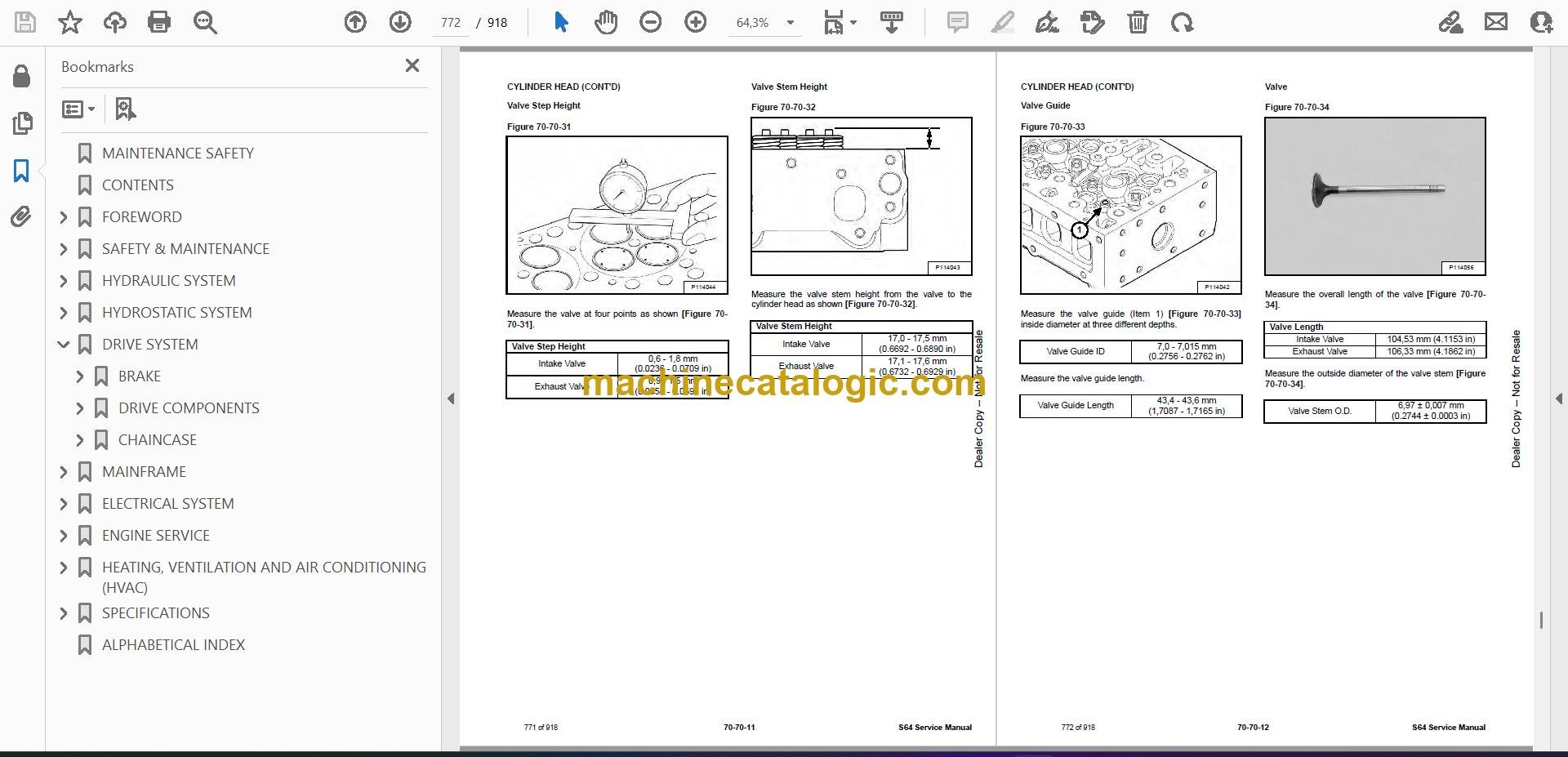
- Valve Step Height
- Valve Stem Height
- Valve Guide
- Valve
- Valve Spring
- Rocker Arm Shaft Disassembly And Assembly
- Rocker Arm Shaft Inspection
- Push Rod Inspection
- CRANKSHAFT AND PISTONS
- Piston And Connecting Rod Removal And Installation
- Piston And Connecting Rod Inspection
- Crankshaft Removal And Installation
- Cylinder Block Inspection
- Crankshaft Inspection
- Connecting Rod Inspection
- Engine Component Class
- CAMSHAFT
- Removal And Installation
- Inspecting
- GEARCASE
- Gearcase Cover Removal And Installation
- Gear Backlash
- Gear Timing
- Idle Gear Removal And Installation
- Idle Gear Inspection
- TURBOCHARGER
- Description
- Removal And Installation
- Inspection
- FLYWHEEL AND HOUSING
- Flywheel Removal And Installation
- Ring Gear Removal And Installation
- Housing Removal And Installation
- EXHAUST GAS RECIRCULATION (EGR) SYSTEM
- Description
- Removal And Installation
- EXHAUST MANIFOLD
- HEATING, VENTILATION AND AIR CONDITIONING (HVAC)
- AIR CONDITIONING SYSTEM FLOW
- Description
- Chart
- Components
- Safety Equipment
- REGULAR MAINTENANCE
- Cleaning HVAC Filters
- Cleaning Air Conditioning Evaporator And Heater Coil
- Cleaning Air Conditioning Condenser
- Lubricating Air Conditioning System
- Troubleshooting HVAC System
- Adjusting Belt
- Replacing Belt
- Air Conditioning Service Chart
- TROUBLESHOOTING
- Blower Motor Does Not Operate
- Blower Motor Operates Normally, But Air Flow Is Insufficient
- Insufficient Cooling Although Air Flow And Compressor Operation Are Normal
- The Compressor Does Not Operate At All, Or Operates Improperly
- Gauge Pressure Related Troubleshooting
- Troubleshooting Tree
- Temperature / Pressure Chart
- Poor A/C Performance
- HVAC Repair And Leaks
- Electrical System
- Engine Coolant Bypassing The Heater Valve
- Heater Valve Not Opening Or Closing
- SYSTEM CHARGING AND RECLAMATION
- Refrigerant Identification
- Reclamation And Charging With Recovery / Charging Unit
- COMPRESSOR
- Removal And Installation
- Oil
- Oil Check
- CONDENSER
- RECEIVER / DRIER FILTER CARTRIDGE
- EVAPORATOR / HEATER UNIT
- THERMOSTAT
- Description
- Removal And Installation
- EXPANSION VALVE
- EVAPORATOR COIL
- HEATER COIL
- BLOWER FAN
- Removal And Installation
- Disassembly And Assembly
- HEATER VALVE
- EVAPORATOR / HEATER COVER
- SPECIFICATIONS
- LOADER SPECIFICATIONS
- Machine Dimensions
- Performance Specifications
- Engine Specifications
- Drive System Specifications
- Control Specifications
- Hydraulic System Specifications
- Hydraulic Cylinder Specifications
- Electrical System Specifications
- Fluid Capacities
- Tire Specifications
- TECHINCAL SERVICE GUIDE SPECIFICATIONS
- Engine
- Engine Torques
- Cooling System
- Loader Torques
- Hydraulic / Hydrostatic System
- Fuel Consumption
- TORQUE SPECIFICATIONS FOR BOLTS
- Torque For General SAE Bolts
- Torque For General Metric Bolts
- HYDRAULIC CONNECTION SPECIFICATIONS
- Straight Thread O-ring Fitting
- Flare Fitting
- Tubelines And Hoses
- HYDRAULIC FLUID SPECIFICATIONS
- CONVERSIONS
- Decimal And Millimeter Equivalent Chart
- U.S. To Metric Conversion Chart
- SERVICE TOOLS REQUIRED
- Remote Start Tools
- Hydraulic Tools
- Mainframe And Drive Tools
- Electrical Tools
- Engine Tools
- HVAC Tools
- ALPHABETICAL INDEX
Bobcat Software
Bobcat PDF Manuals


