$ 0
0
$ 0
0

Bobcat T40140 VersaHANDLER® TTC, Telescopic Handler Service Manual (SN 363212001-363299999)

Format: PDF (Printable Document)

File Language: English

File Pages: 712

File Size: 26.50 MB (Speed Download Link)

Brand: Bobcat

Model: T40140 VersaHANDLER® TTC, Telescopic Handler

Book No: 4950145

Serial No: SN 363212001-363299999

Type of Document: Service Manual

Categories: ,

$ 45

Share:

Bobcat T40140 VersaHANDLER® TTC, Telescopic Handler Service Manual (SN 363212001-363299999)

A T40140 VersaHANDLER is the kind of telehandler you see unloading pallets of block, lifting trusses, or stacking materials where a skid-steer just can't reach. The service manual is what I grab when I'm in a muddy yard with a laptop on the tire and I need the exact teardown steps or test points, not guesses. People use it when a machine is out of warranty, downtime hurts, and they want to fix hydraulics, driveline, or electrical issues the same way a dealer shop would.

What this manual helps you do

  • Trace hydraulic circuits for boom lift, crowd, and stabilizers so you can pinpoint weak or dead functions.
  • Check and set test-port pressures on the hydrostatic and hydraulic systems using the right ports and sequences.
  • Follow step-by-step teardown and reassembly for boom sections, cylinders, drive components, and major linkages.
  • Diagnose electrical faults with proper wiring diagrams so you're not chasing the wrong relay or sensor.
  • Replace and adjust wear items like brakes, axles, steering, and attachment controls with the correct procedures.

Who this is for

This is for anyone maintaining or repairing a Bobcat T40140 telehandler in the serial range 363212001 to 363299999: small contractors, rental fleets, shop mechanics, and owner-operators who wrench on their own gear. If you only need basic controls, safety info, or daily checks, you want the operator's handbook instead, not this manual.

FAQ

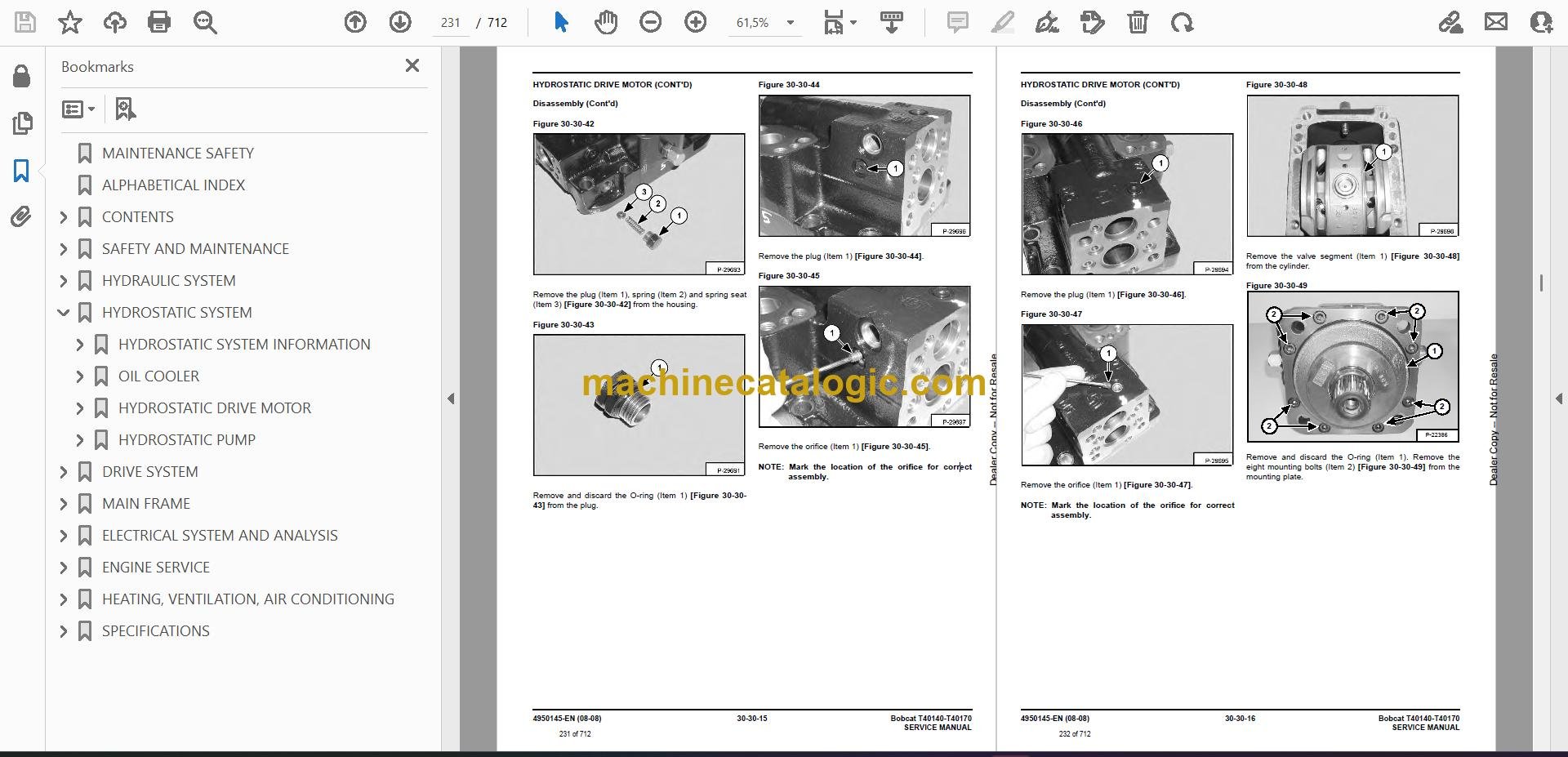
Q: Is this a searchable PDF with readable wiring diagrams?

A: Yes, manuals like this are normally supplied as a searchable PDF and the wiring diagrams are laid out so you can zoom in and read connector labels.

Q: How do I know if it fits my machine?

A: Check your T40140 serial number plate. If it falls between 363212001 and 363299999, this is the right manual.

Q: Is this the right document if I'm planning engine or hydraulic repairs?

A: Yes, this is the workshop-level service manual you'd use for real diagnostics and repairs, not just basic operation.

Bottom line: If you own or service a T40140 in that serial range and plan to do your own repairs, this is the manual you want. If you're just learning to run the machine, skip it.

📘 Show Index

Table of Contents:

  • MAINTENANCE SAFETY
  • ALPHABETICAL INDEX
  • CONTENTS
    • FOREWORD
    • SAFETY INSTRUCTIONS
    • FIRE PREVENTION
      • Maintenance
      • Operation
      • Electrical
      • Hydraulic System
      • Fueling
      • Starting
      • Welding And Grinding
      • Fire Extinguishers
    • SERIAL NUMBER LOCATIONS
      • Telescopic Handler Serial Number
      • Engine Serial Number
      • Other Serial Numbers
      • Delivery Report
  • SAFETY AND MAINTENANCE
    • LIFTING AND BLOCKING THE TELESCOPIC HANDLER
      • Procedure
    • OPERATOR CAB
      • Emergency Exit
      • Cab Door
      • Cab Door Window
    • TRANSPORTING THE TELESCOPIC HANDLER
      • Procedure
    • TOWING THE TELESCOPIC HANDLER
      • Procedure
    • SERVICE SCHEDULE
    • AIR CLEANER SERVICE
      • Replacing Filter Element
    • ENGINE COOLING SYSTEM
      • Cleaning The Cooling System
      • Checking The Coolant Level
      • Replacing The Coolant
    • FUEL SYSTEM
      • Fuel Specifications
      • Filling The Fuel Tank
      • Fuel Filter
    • ENGINE LUBRICATION SYSTEM
      • Checking Engine Oil
      • Oil Chart
      • Replacing Oil And Filter
    • HYDRAULIC / HYDROSTATIC SYSTEM
      • Checking And Adding Fluid
      • Replacing Hydraulic / Hydrostatic Filter
      • Replacing Hydraulic Fluid
    • AXLES (FRONT AND REAR)
      • Checking Oil Level (Planetary Carrier)
      • Draining Oil (Planetary Carrier)
      • Checking Oil Level (Rear Differential)
      • Draining Oil (Rear Differential)
      • Checking Oil Level (Front Differential)
      • Draining Oil (Front Differential)
    • LUBRICATION
      • Procedure
    • TIRE MAINTENANCE
      • Wheel nuts
      • Tire Rotation
      • Tire Mounting
    • APPROVED BOOM STOP
      • Installing The Approved Boom Stop
      • Removing The Approved Boom Stop
    • ENGINE COVER
      • Opening And Closing The Engine Cover
  • HYDRAULIC SYSTEM
    • HYDRAULIC SYSTEM INFORMATION
      • Glossary Of Hydraulic / Hydrostatic Symbols
      • Troubleshooting Chart
      • Tightening Procedures
    • LIFT CYLINDER
      • Removal And Installation
      • Parts Identification
      • Disassembly
      • Assembly
    • BUCKET POSITIONING CYLINDER
      • Removal And Installation
    • BUCKET POSITIONING CYLINDER (CONT’D)
      • Parts Identification
      • Disassembly
      • Assembly
    • EXTENSION CYLINDER
      • Cylinder Group Removal And Installation
      • Parts Identification
      • Disassembly
      • Assembly
    • TILT CYLINDER
      • Removal And Installation
      • Parts Identification
      • Disassembly
      • Assembly
    • STEERING CYLINDER (FRONT)
      • Removing the Steering Cylinder
      • Disassembling the Steering Cylinder
      • Assembling the Steering Cylinder
    • STEERING CYLINDER (REAR)
      • Removing the Steering Cylinder
      • Installing the Steering Cylinder
      • Disassembling the Steering Cylinder
      • Assembling the Steering Cylinder
    • DRIVE BOX
      • Parts Identification
      • Disassembly
      • Assembly
      • Special Tools
    • MAIN RELIEF VALVE
      • Testing And Adjustment
      • Removal and Installation
    • QUICK TACH CYLINDER
      • Removal And Installation
      • Parts Identification
      • Disassembly
      • Assembly
    • FRAME LEVELING CYLINDER
      • Removal And Installation
      • Parts Identification
      • Disassembly
      • Assembly
    • STEERING MODE VALVE BLOCK
      • Removal And Installation
      • Parts Identification
      • Disassembly
      • Solenoid Testing
      • Assembly
    • BRAKE VALVE
      • Removal And Installation
      • Disassembly And Assembly
    • GEAR PUMP
      • Removal And Installation
      • Parts Identification
      • Disassembly And Assembly
    • FAN MOTOR
      • Removal And Installation
      • Parts Identification
      • Disassembly And Assembly
    • HYDRAULIC RESERVOIR
      • Removal And Installation
    • STEERING VALVE
      • Removal And Installation
      • Parts Identification
      • Disassembly
      • Inspection
      • Assembly
    • HYDRAULIC CONTROL VALVE
      • Checking Drain Pressure
      • Valve Section Troubleshooting (Auxiliary Section Example)
      • Removal And Installation
      • Parts Identification
      • Section Removal
      • Section Disassembly And Assembly
      • Inlet Section Disassembly And Assembly
    • PORT RELIEF VALVES
      • Removal And Installation
    • FLOW CONTROL VALVE
      • Removal And Installation
    • PARKING BRAKE
      • Parking Brake Valve Removal And Installation
      • Parking Brake Valve Disassembly And Assembly
    • PRESSURE REDUCING VALVE
      • Testing
      • Removal And Installation
    • ACCUMULATOR
      • Removal And Installation
    • TOW VALVE
      • Removal And Installation
      • Disassembly And Assembly
    • STABILIZER CYLINDER
      • Removal And Installation
      • Parts Identification
      • Disassembly
      • Assembly
    • STABILIZER CONTROL VALVE
      • Parts Identification
      • Removal
  • HYDROSTATIC SYSTEM
    • HYDROSTATIC SYSTEM INFORMATION
      • Troubleshooting Chart
      • Replenishing Valve Function
    • OIL COOLER
      • Description
    • HYDROSTATIC DRIVE MOTOR
      • Removal And Installation
      • Parts Identification
      • Disassembly
      • Inspection
      • Assembly
    • HYDROSTATIC PUMP
      • Removal And Installation
      • Parts Identification
      • Disassembly
      • Inspection
      • Assembly
  • DRIVE SYSTEM
    • TROUBLESHOOTING
      • Chart
    • AXLE AND DIFFERENTIAL (FRONT)
      • General Information
      • Planetary Carrier Parts Identification
      • Planetary Carrier Disassembly
      • Steering Knuckle and Drive Axle Parts Identification
      • Steering Knuckle Disassembly
      • Drive Axle Disassembly
      • Brake system Identification
      • Brake System Disassembly
      • Differential Parts Identification
      • Differential Disassembly
      • Bevel pinion Parts Identification
      • Bevel Pinion Disassembly
      • Bevel Pinion Assembly
      • Differential assembly
      • Brake System Assembly
      • Drive Axle Assembly
      • Steering Knuckle Assembly
      • Planetary carrier Assembly
      • Special Tools
    • AXLE AND DIFFERENTIAL (REAR)
      • General Information
      • Planetary Carrier Parts Identification
      • Steering Knuckle and Drive Axle Parts Identification
      • Steering Knuckle Disassembly
      • Differential and Bevel Pinion Parts Identification
      • Differential Disassembly
      • Bevel pinion Disassembly
      • Bevel pinion Assembly
      • Differential Assembly
      • Steering Knuckle Assembly
      • Planetary Carrier Assembly
      • Special tools
    • FRONT AXLE
      • Removal
    • AXLE TOE-IN
      • Adjustment
    • PARKING BRAKE
      • Releasing The Brake For Towing
      • Re-Activating The Brake
    • STEERING ANGLE ADJUSTMENT
      • Adjustment
    • DRIVESHAFT
      • Removal And Installation
    • SERVICE BRAKE
      • Description
      • Bleeding The Brake Circuit
    • REAR AXLE
      • Removal
  • MAIN FRAME
    • OPERATOR CAB
      • Removal and Installation
    • OPERATOR SEAT
      • Removal And Installation
    • BOOM ASSEMBLY
      • Removal And Installation
    • END BOOM
      • Removal
      • Installation
    • WEAR PADS (FRONT)
      • Removal
      • Installation
    • WEAR PADS (REAR)
      • Removal
      • Installation
    • ENGINE COVER
      • Gas Cylinder Removal And Installation
      • Removal And Installation
    • AIR INTAKE COWLING
      • Removal And Installation
    • FUEL TANK
      • Removal And Installation
    • QUICK TACH
      • Removal And Installation
    • REAR WEIGHTS
      • Removal And Installation
    • FENDER
      • Removal And Installation
    • FRONT WEIGHT
      • Removal And Installation
    • DASH COVER / STEERING COLUMN COVER
      • Removal And Installation
    • JOYSTICK PANEL
      • Removal And Installation
    • INTERMEDIATE BOOM
      • Removal of the First Intermediate Boom (T40170 & T40140)
      • Installation of the First Intermediate Boom (T40170 & T40140)
      • Removal of the Second Intermediate Boom (T40170)
      • Installation of the Second Intermediate Boom (T40170)
    • BOOM TRAY
      • Removal And Installation
    • CHAIN CHECKING AND ADJUSTING PROCEDURE
      • Checking The Tension Of The Telescoping Chains Of The T40140 / T40170
    • STABILIZER FRAME
      • Removal
  • ELECTRICAL SYSTEM AND ANALYSIS
    • ELECTRICAL SYSTEM INFORMATION
      • Description
      • Checking The Battery Fluid Level
      • Checking The State of Fuses, Diodes And Relays
      • Checking The Working Order of Controls, Lighting And Signalling
      • Checking The State of Electric Connections
      • Fuses, Diodes & Relays
      • Fuses And Diodes
      • Relays
    • BATTERY
      • Removal And Installation
      • Servicing
      • Using A Booster Battery (Jump Starting)
    • ALTERNATOR
      • Removal And Installation
      • Adjusting The Alternator Belt
    • STARTER
      • Removal And Installation
      • Assembly / disassembly
    • LIGHTS
      • Rear Light Removal And Installation
      • Front Light Removal And Installation
    • TRAVEL / SIGNAL LEVER
      • Removal And Installation
    • INSTRUMENT PANEL
      • Removal And Installation
    • SWITCH PANEL
      • Removal And Installation
    • BRAKE LIGHT SWITCH
      • Removal And Installation
      • Adjustment
    • FRONT WIPER MOTOR
      • Removal And Installation
    • TOP WIPER MOTOR
      • Removal And Installation
    • REAR WIPER MOTOR
      • Removal And Installation
    • PEDAL ASSEMBLY
      • Removal And Installation
      • Disassembly And Assembly
    • INCHING SWITCH
      • Removal And Installation
      • Adjustment
    • SERVICE SOFTWARE
      • Connecting The Laptop Computer
      • Entering The Service Software
      • Monitor Screen
      • Warnings Screen
      • Calibrate Inch Pedal
      • Calibrate Creep Potentiometer
      • Program / Update Susmic Controller
    • FRAME LEVEL SPEED SWITCH
      • Description
      • Removal
      • Installation
      • Disassembly And Assembly
    • JOYSTICK
      • Removal And Installation
  • ENGINE SERVICE
    • TROUBLESHOOTING
      • Chart
    • ENGINE SPEED CONTROL
      • Removal And Installation
    • MUFFLER
      • Removal And Installation
    • AIR CLEANER
      • Housing Removal And Installation
    • OIL COOLER / RADIATOR
      • Removal And Installation
      • Disassembly And Assembly
    • ENGINE AND ENGINE MOUNTS
      • Removal And Installation
    • ENGINE COMPONENTS AND TESTING
      • Fuel Injection Pump Removal
      • Fuel Injection Pump Installation
      • Fuel Injectors Removal And Installation
      • Checking The Fuel Lift Pump
      • Fuel Lift Pump Removal And Installation
      • Compression Checking
      • Glow Plugs Checking
      • Glow Plugs Removal And Installation
    • ENGINE TIMING
      • Procedure
    • ENGINE / HYDROSTAT ASSEMBLY
      • Removal And Installation
    • FLYWHEEL AND HOUSING
      • Removal And Installation
      • Ring Gear Removal
      • Ring Gear Installation
    • RECONDITIONING THE ENGINE
      • Turbo Charger Troubleshooting
      • Turbo Charger Description
      • Turbo Charger Removal And Installation
      • Exhaust Manifold Removal And Installation
      • Fuel Injector Cover Removal And Installation
      • Rocker Cover Removal And Installation
      • Cylinder Head Removal
      • Cylinder Head Inspection
      • Cylinder Head Installation
      • Rocker Shaft Disassembly And Assembly
      • Valve Removal
      • Valve Springs Checking
      • Valve Depth Checking
      • Valve Guides Checking
      • Valve Guide Removal
      • Valve Guide Installation
      • Valves Checking
      • Cutting A Valve Seat
      • Valve Seat Assembly
      • Changing Valve Springs (With Cylinder Head Installed)
      • Valve Clearance Adjustment
      • Timing Case And Drive Assembly Description
      • Timing Cover Removal
      • Timing Cover Installation
      • Crankshaft Pulley Removal And Installation
      • Front Oil Seal Removal And Installation
      • Timing Case And Gear Removal
      • Timing Case And Gear Installation
      • Camshaft And Tappets Removal
      • Camshaft And Tappets Installation
      • Pistons And Connecting Rods Description
      • Pistons And Connecting Rods Removal
      • Pistons And Connecting Rods Disassembly
      • Piston Ring End Gap
      • Piston Ring Installation
      • Piston Ring Groove Clearance
      • Connecting Rod Inspection
      • Connecting Rod Bushing Replacement
      • Piston And Connecting Rod Assembly
      • Piston And Connecting Rod Installation
      • Checking Piston Height
      • Crankshaft And Bearings Description
      • Crankshaft And Bearings Removal
      • Inspection Of Crankshaft And Bearings
      • Crankshaft And Bearings Installation
      • Rear Oil Seal Removal
      • Rear Oil Seal Housing Positioning
      • Rear Oil Seal Installation
      • Checking Crankshaft End Play
      • Cooling System Description
      • Thermostat Removal and Installation
      • Thermostat Testing
      • Lubricating Oil Cooler Removal And Installation
      • Water Pump Removal
      • Water Pump Installation
      • Engine Lubrication System Description
      • Oil Filter Adapter Removal And Installation
      • Oil Pan Removal And Installation
      • Oil Screen And Pick-up Tube
      • Oil Pump Removal
      • Oil Pump Installation
      • Oil Pump Disassembly And Assembly
      • Oil Pressure Relief Valve Disassembly And Assembly
      • Engine Block Description
      • Engine Block Disassembly And Assembly
      • Piston Cooling Jet Removal
      • Piston Cooling Jet Installation
      • Piston Cooling Jet Alignment
      • Inspection
      • Cylinder Liner Inspection
      • Cylinder Liner Removal
      • Cylinder Liner Installation
  • HEATING, VENTILATION, AIR CONDITIONING
    • AIR CONDITIONING SYSTEM FLOW
      • Principals
      • Chart
    • COMPONENTS
      • Identification
    • SAFETY
      • Safety Equipment
    • REGULAR MAINTENANCE
      • Filter Element Removal And Installation
      • Compressor Drive Belt Inspection
      • Cleaning The Condenser
    • BASIC TROUBLESHOOTING
      • Poor A/C Performance
      • Compressor Drive Belt Inspection
      • Checking The Electrical System
    • GENERAL AIR CONDITIONING SERVICE GUIDELINES
      • Compressor Oil
      • Compressor Oil Check
      • Component Replacement And Refrigeration Leaks
    • SYSTEM TROUBLESHOOTING CHART
    • TEMPERATURE / PRESSURE
      • Chart
    • AIR CONDITIONING SERVICE
      • Chart
    • SYSTEM CHARGING AND RECLAMATION
      • Reclamation Procedure
      • Charging Procedure With A Manifold Gauge Set
      • Charging Procedure
    • COMPRESSOR
      • Removal And Installation
      • Compressor Clutch Disassembly And Assembly
    • CONDENSER
      • Removal And Installation
    • RECEIVER / DRIER
      • Removal And Installation
    • PRESSURE SWITCH
      • Removal And Installation
    • EVAPORATOR / BLOWER UNIT
      • Removal And Installation
    • EXPANSION VALVE
      • Removal And Installation
    • HEATER ASSEMBLY
      • Removal And Installation
      • Fan Removal And Installation
      • Core Removal And Installation
  • SPECIFICATIONS
    • TELESCOPIC HANDLER SPECIFICATIONS
      • Dimensional Specifications T40140
      • Dimensional Specifications T40170
      • Performance Specifications
      • Engine
      • Controls
      • Drive System
      • Tires
      • Capacities
      • Hydraulic System
      • Electrical System
      • Instrument Panel
    • ENGINE SPECIFICATIONS
      • General
      • Cylinder Head
      • Valve Guides
      • Exhaust Valves
      • Intake Valves
      • Valve Springs
      • Rocker Shaft, Rockers And Bushings
      • Pistons And Piston Rings
      • Connecting Rods And Bearings
      • Crankshaft
      • Crankshaft Re-Grind Data
      • Main Bearings
      • Thrust Washers
      • Camshaft And Thrust Washer
      • Cylinder Block
      • Cylinder Liners
      • Fuel Injection Pump
      • Fuel Injectors
      • Fuel Lift Pump
      • Timing Case And Timing Gears
      • Oil Pump, Gear And Relief Valve
      • Turbocharger
      • Flywheel
      • Water Pump And Thermostat
      • Engine Torque Component
    • MACHINE TORQUE SPECIFICATIONS
      • Axle
      • Boom
      • Drive Box
      • Drive Motor
      • Engine
      • Hydraulic Pump
    • TORQUE SPECIFICATIONS FOR BOLTS
      • Torque for General SAE Bolts
      • Torque For General Metric Bolts
    • HYDRAULIC CONNECTION SPECIFICATIONS
      • O-ring Face Seal Connection
      • Straight Thread O-ring Fitting
      • Tubelines And Hoses
      • Flare Fitting
      • O-ring Flare Fitting
      • Port Seal Fitting
    • HYDRAULIC / HYDROSTATIC FLUID SPECIFICATIONS
      • Specifications
    • CONVERSIONS
      • Decimal And Millimeter Equivalents
      • U.S. To Metric Conversion

Bobcat Software

Bobcat PDF Manuals

Related Manuals

0
    0
    Your Cart
    Your cart is emptyReturn to Shop