$ 0
0
$ 0
0

Bobcat 553 Loader Service Manual (SN 520311001-520399999)

Format: PDF (Printable Document)

File Language: English

File Pages: 410

File Size: 13.94 MB (Speed Download Link)

Brand: Bobcat

Model: 553 Loader

Book No: 6901824

Serial No: SN 520311001-520399999

Type of Document: Service Manual

Categories: ,

$ 45

Share:

Bobcat 553 Loader Service Manual (SN 520311001-520399999)

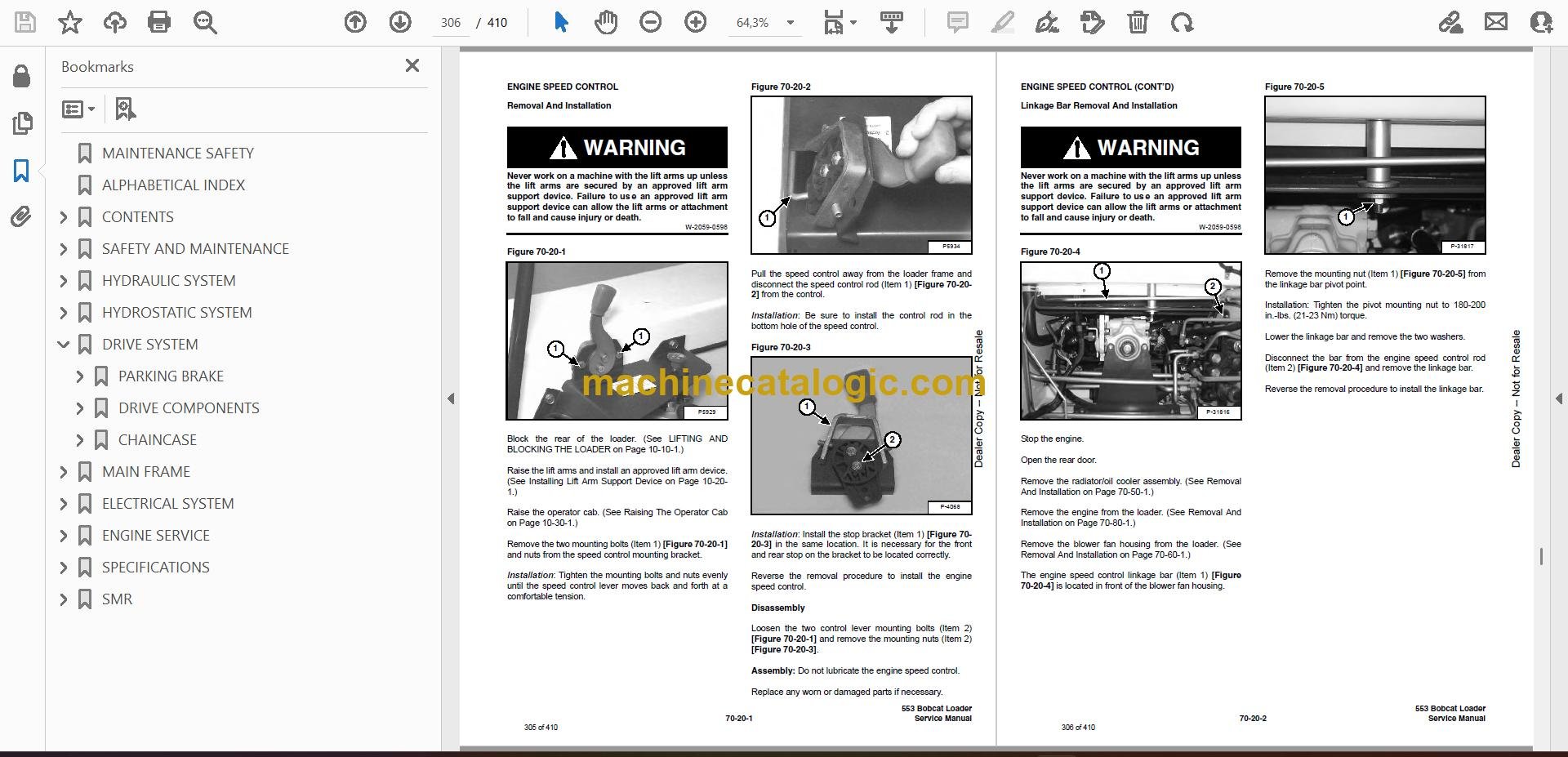
A Bobcat 553 is a small skid-steer that ends up in tight spots, cleaning barns, loading mulch, or shuttling pallets where a bigger machine won't fit. The person who reaches for this service manual is the one with tools in the truck, trying to fix a leak, chase an electrical fault, or get a dead loader moving again without waiting a week for the dealer. They need step-by-step teardown info, test port locations, and what "normal" looks like on pressures and measurements. That's exactly the kind of thing this manual is meant for.

What this manual helps you do

  • Trace and diagnose hydraulic problems in the loader and drive circuits on a 553 in the 520311001-520399999 serial range
  • Check, set, and verify hydrostatic and control adjustments after component replacement or repair
  • Follow step-by-step procedures to remove, disassemble, and rebuild major components like drive motors, cylinders, and linkages
  • Diagnose electrical issues using wiring diagrams, connector callouts, and system descriptions specific to this serial range
  • Replace and adjust engine and drivetrain parts with the right sequences and specs instead of guessing in the customer's yard

Who this is for

This is for a small contractor, rental fleet, shop mechanic, or owner-operator working on a Bobcat 553 with a serial number between 520311001 and 520399999. If you only need basic controls, safety, and daily checks, you want the operator's handbook instead, not this manual.

FAQ

Q: Is this a searchable PDF, and are the wiring diagrams readable?

A: These manuals are usually scanned or native PDFs that you can search, and the wiring diagrams are laid out so you can zoom in and read pin numbers and wire colors.

Q: How do I know it fits my machine?

A: Check the loader's serial tag. If it falls between 520311001 and 520399999, this is the right service manual for your 553.

Q: Is this the right document if I'm doing real repairs, not just maintenance?

A: Yes. This is the workshop-level service manual, meant for actual diagnostics, teardown, and reassembly, not just fluid changes.

Bottom line: If your 553's serial number is in that 520311001-520399999 window and you're doing your own repairs, this is the manual you want. If the serial does not match, skip it.

📘 Show Index

Table of Contents:

  • MAINTENANCE SAFETY
  • ALPHABETICAL INDEX
  • CONTENTS
    • FOREWORD
    • SAFETY INSTRUCTIONS
      • Fire Prevention
    • SERIAL NUMBER LOCATION
      • Loader Serial Number
      • Engine Serial Number
    • DELIVERY REPORT
    • BOBCAT LOADER IDENTIFICATION
  • SAFETY AND MAINTENANCE
    • LIFTING AND BLOCKING THE LOADER
      • Procedure
    • LIFT ARM SUPPORT DEVICE
      • Installing Lift Arm Support Device
      • Removing Lift Arm Support Device
    • OPERATOR CAB
      • Description
      • Raising The Operator Cab
      • Lowering The Operator Cab
      • Emergency Exit
    • TRANSPORTING THE BOBCAT LOADER
      • Procedure
      • Stopping The Bobcat Loader
    • TOWING THE LOADER
      • Procedure
    • REMOTE START
      • Procedure
    • SERVICE SCHEDULE
      • Chart
    • AIR CLEANER SERVICE
      • Replacing Filter Element
    • ENGINE COOLING SYSTEM
      • Cleaning The Cooling System
      • Checking The Coolant Level
      • Replacing The Coolant
    • FUEL SYSTEM
      • Fuel Specifications
      • Filling The Fuel Tank
      • Fuel Filter
      • Removing Air From The Fuel System
    • ENGINE LUBRICATION SYSTEM
      • Checking Engine Oil
      • Oil Chart
      • Replacing Oil And Filter
    • HYDRAULIC/HYDROSTATIC SYSTEM
      • Description
      • Checking And Adding Fluid
      • Replacing The Hydraulic/Hydrostatic Filter
      • Replacing Hydraulic Fluid
    • FINAL DRIVE TRANSMISSION (CHAINCASE)
      • Checking And Adding Oil
    • AUXILIARY CONTROL LOCKBOLT
      • Removal
    • BOB-TACH
      • Inspection And Maintenance
    • LUBRICATION OF THE BOBCAT LOADER
      • Procedure
    • TIRE MAINTENANCE
      • Wheel Nuts
      • Rotating
      • Mounting
    • SPARK ARRESTOR MUFFLER
      • Cleaning Procedure
    • PIVOT PINS
      • Procedure
    • SEAT BAR RESTRAINT SYSTEM
      • Description
      • Seat Bar Inspection
      • Seat Bar Maintenance
    • RUBBER COUPLER LUBRICATION
      • Procedure
  • HYDRAULIC SYSTEM
    • HYDRAULIC/HYDROSTATIC SCHEMATICS
    • HYDRAULIC SYSTEM INFORMATION
      • Tighten Procedures
      • Troubleshooting Chart
    • CYLINDER (LIFT)
      • Checking
      • Removal And Installation
      • Identification
      • Disassembly And Assembly
    • CYLINDER (TILT)
      • Checking
      • Removal And Installation
      • Identification
      • Disassembly And Assembly
    • MAIN RELIEF VALVE
      • Checking The Main Relief Valve Without Auxiliaries
      • Checking The Main Relief Valve With Auxiliaries
      • Removal and Installation
    • HYDRAULIC CONTROL VALVE
      • Removal And Installation
      • Identification Chart
      • Disassembly And Assembly
      • Load Check Valve
      • Main Releif Valve
      • Anti-Cavitation Check Valve
      • Port Relief Valve
      • Rubber Boot (Lift)
      • Rubber Boot (Tilt)
      • Rubber Boot (Aux.)
      • Lift Spool Detent
      • Tilt Centering Spring
      • Auxiliary Spool Detent
      • One Way Restrictors
      • Inspection
      • Spool Seal Installation
    • LIFT ARM BY-PASS CONTROL VALVE
      • Inspecting
      • Removal and Installation
      • Disassembly and Assembly
    • TILT LOCK VALVE
      • Removal And Installation
      • Disassembly and Assembly
    • HYDRAULIC PUMP
      • Check The Output Of The Hydraulic Pump
      • Removal And Installation
      • Identification
      • Disassembly And Assembly
      • Inspection
    • HYDRAULIC FILTER HOUSING
      • Removal and Installation
    • HYDRAULIC FLUID RESERVOIR
      • Removal and Installation
  • HYDROSTATIC SYSTEM
    • HYDROSTATIC SYSTEM INFORMATION
      • Troubleshooting Chart
      • Replenishing Valve Function
    • CONTROL PANEL
      • Removal and Installation
    • STEERING
      • Lever Removal and Installation
      • Lever Disassembly And Assembly
      • Linkage Removal And Installation
      • Pintle Lever Disassemby And Assembly
      • Linkage Neutral Adjustment
    • HYDROSTATIC MOTOR
      • Removal And Installation
      • Parts Identification
      • Disassembly And Assembly
      • Inspection
      • Timing The Hydrostatic Motor
    • PORT BLOCK
      • Removal And Installation
      • Oil Cooler By-Pass Valve
      • Hydraulic Oil Temperature Switch
      • Charge Pressure By-Pass Valve
    • HYDROSTATIC PUMP
      • Checking Charge Pressure
      • Removal And Installation
      • Drive Coupler Removal And Installation
      • Parts Identification
      • Disassembly And Assembly
      • Inspection
    • OIL COOLER
      • Removal and Installation
  • DRIVE SYSTEM
    • PARKING BRAKE
      • Disk Removal And Installation
      • Traction Lock Guides Removal And Installation
    • DRIVE COMPONENTS
      • Axle Seal Removal And Installation
      • Axle, Bearing, And Sprocket Removal And Installation
      • Chain Removal And Installation
    • CHAINCASE
      • Removing Oil From The Chaincase
      • Front Cover Removal And Installation
      • Rear Cover Removal And Installation
  • MAIN FRAME
    • SEAT BAR
      • Removal And Installation
      • Assembling Components
      • Compression Spring Disassembly And Assembly
    • OPERATOR CAB
      • Gas Cylinder Removal And Installation
      • Gas Cylinder Disassembly And Assembly
      • Removal And Installation
    • OPERATOR SEAT
      • Removal And Installation
      • Seat Belt Removal And Installation
    • BOB-TACH
      • Removal And Installation
      • Bob-Tach Lever And Wedge
    • LIFT ARM
      • Removal And Installation
    • REAR GRILL
      • Removal And Installation
    • REAR DOOR
      • Removal And Installation
      • Striker Removal and Installation
      • Striker Disassembly and Assembly
      • Adjusting The Striker
      • Latch Removal and Installation
    • FUEL TANK
      • Removal And Installation
      • Fuel Level Sender
    • CONTROL PEDALS
      • Removal And Installation
      • Pedal Adjustment
      • Pedal Interlock Linkage Removal And Installation
      • Pedal Interlock Linkage Adjustment
      • Crossbar Linkage Removal And Installation
  • ELECTRICAL SYSTEM
    • ELECTRICAL SCHEMATICS
    • ELECTRICAL SYSTEM INFORMATION
      • Troubleshooting
      • Description
      • Fuse Location
      • Relay Switches Location
    • BATTERY
      • Removal And Installation
      • Using A Booster Battery (Jump Starting)
    • ALTERNATOR
      • Removal And Installation
      • Adjusting The Alternator Belt
      • Description
      • Tests
      • Alternator Output Test
      • Full Field Test
      • Alternator Regulator Test
      • Alternator Regulator Test Using Voltmeter
      • Parts Identification
      • Pulley Removal And Installation
      • Disassembly And Assembly
      • Rotor Continuity Test
      • Stator Continuity Test
      • Rectifier Continuity (Diode) Test
      • Brush Length
    • STARTER
      • Removal And Installation
      • Checking The Starter In The Loader
      • Parts Identification
      • Disassembly
      • Inspection And Repair
      • No Load Test
      • Assembly
    • INSTRUMENT PANEL
      • Removal And Installation
    • LIGHTS
      • Front Removal And Installation
    • BICS™ SYSTEM CONTROLLER
      • Trouble Shooting Guide
      • Removal And Installation
    • BICS™ SYSTEM (WITH PRESS TO OPERATE BUTTON)
      • Inspecting The BICS™ Controller (Engine STOPPED – Key ON)
      • Inspecting Deactivation Of The Auxiliary Hydraulics System (Engine STOPPED – Key ON)
      • Inspecting The Seat Bar Sensor (Engine RUNNING)
      • Inspecting The Traction Lock (Engine RUNNING)
      • Inspecting The Lift Arm By-Pass Control
      • Additional Inspection For Loaders With Advanced Hand Controls
      • Troubleshooting Chart
    • SEAT BAR SENSOR
      • Troubleshooting Guide
      • Seat Bar Sensor Test
      • Removal And Installation
      • BICS™ Controller Seat Bar Sensor Circuit Test
    • TRACTION LOCK
      • Troubleshooting Guide
      • Removal And Installation
  • ENGINE SERVICE
    • TROUBLESHOOTING
      • Chart
    • ENGINE SPEED CONTROL
      • Removal And Installation
      • Disassembly
      • Linkage Bar Removal And Installation
    • ENGINE SPEED CONTROL PLATE
      • Removal And Installation
      • Governor Spring Removal
      • Start Spring Removal
      • Idle Limit And Fuel Limit Adjustment
    • MUFFLER
      • Removal And Installation
    • AIR CLEANER
      • Removal And Installation
    • RADIATOR
      • Removal And Installation
    • BLOWER FAN HOUSING
      • Removal And Installation
    • ENGINE COMPONENTS AND TESTING
      • Compression Checking
      • Glow Plugs Checking
      • Glow Plugs Removal And Installation
      • Fuel Shut-Off Solenoid, Removal And Installation
      • Fuel Lift Pump Removal And Installation
      • Fuel Injection Pump, Checking
      • Fuel Injection Pump Removal And Installation
      • Timing The Injection Pump
      • Fuel Injector Nozzles Removal And Installation
      • Checking Fuel Injector Nozzles
      • Engine Timing Installation
    • ENGINE
      • Removal And Installation
      • Engine Mounting Brackets Removal And Installation
    • FLYWHEEL
      • Removal And Installation
      • Flywheel Ring Gear
      • Housing Removal And Installation
    • RECONDITIONING THE ENGINE
      • Thermostat Removal And Installation
      • Water Pump Removal And Installation
      • Timing Gear Case Cover Removal And Installation
      • Oil Pump Removal And Installation
      • Crankshaft Front Seal Removal And Installation
      • Exhaust Manifold Removal And Installation
      • Valve Cover Removal And Installation
      • Rocker Arm Removal And Installation
      • Push Rod Removal And Installation
      • Tappet Removal And Installation
      • Cylinder Head Removal And Installation
      • Checking Piston Top Clearance
      • Disassembly
      • Assembly
      • Servicing The Cylinder Head
      • Combustion Chamber Removal And Installation
      • Idler Gear Removal And Installation
      • Camshaft Removal And Installation
      • Fuel Camshaft Removal And Installation
      • Oil Pan Removal And Installation
      • Governor Shaft Removal And Installation
      • Governor Fork Lever Removal And Installation
      • Piston Removal And Installation
      • Checking The Piston And Connecting Rod
      • Connecting Rod Alignment
      • Pison Ring Gap
      • Piston Ring Installation
      • Connecting Rod Installation
      • Checking Engine Cylinder Bore
      • Crankshaft Removal And Installation
      • Checking Crankshaft Journal And Block Bearing
      • Checking The Crankshaft Journal And Main Bearing
      • Connecting Rod Journal
      • Checking the End Play Of The Crankshaft
      • Crankshaft Alignment
      • Idler Gear And Crankshaft
      • Idler Gear And Crankshaft Gear
      • Idler Gear And Fuel Camshaft Gear
      • Fuel Camshaft Gear And Governor Shaft Gear
    • RUBBER DRIVE COUPLER
      • Removal And Installation
      • Disassembly
      • Assembly
    • WATER FLANGE
      • Removal And Installation
  • SPECIFICATIONS
    • LOADER SPECIFICATIONS
      • Machine Dimensions
      • Performance
      • Controls
      • Engine
      • Hydraulic System
      • Electrical
      • Drive System
      • Capacities
      • Tires
    • ENGINE SPECIFICATIONS
      • Engine Compression
      • Fuel Injection Nozzles
      • Fuel Injection Pump
      • Cylinder Head
      • Valves
      • Valve Springs
      • Rocker Arms
      • Camshaft
      • Cylinders
      • Piston Rings
      • Pistons
      • Crankshaft
      • Oil Pump
      • Thermostat
      • Crankshaft Re-Grind Data
    • TORQUE SPECIFICATIONS FOR BOLTS
      • Torque For General SAE Bolts
      • Torque For General Metric Bolts
    • HYDRAULIC CONNECTION SPECIFICATIONS
      • O-ring Face Seal Connection
      • Straight Thread O-ring Fitting
      • Tubelines And Hoses
      • Flare Fitting
      • O-ring Flare Fitting
      • Port Seal Fitting
    • HYDRAULIC FLUID SPECIFICATIONS
      • Specifications
    • CONVERSIONS
      • Decimal And Millimeter Equivalents
      • U.S. To Metric Conversion
  • SMR
    • 553-1
    • 553-2

Bobcat Software

Bobcat PDF Manuals

Related Manuals

0
    0
    Your Cart
    Your cart is emptyReturn to Shop