$ 0
0
$ 0
0

Bobcat 5600 Toolcat™ Utility Work Machine Service Manual (SN AHG811001-AHG899999)

Format: PDF (Printable Document)

File Language: English

File Pages: 790

File Size: 26.77 MB (Speed Download Link)

Brand: Bobcat

Model: 5600 Toolcat™ Utility Work Machine

Book No: 6990860

Serial No: SN AHG811001-AHG899999

Type of Document: Service Manual

Categories: ,

$ 45

Share:

Bobcat 5600 Toolcat™ Utility Work Machine Service Manual (SN AHG811001-AHG899999)

The Bobcat 5600 Toolcat is the Swiss Army knife of a property or jobsite. It plows snow, runs hydraulic attachments, hauls pallets, and shuttles material all day. The person who reaches for this service manual is the one who actually has to keep it moving: shop mechanic, field tech, or an owner-operator who does their own repairs. They're trying to get hard data for real work: hydraulic test points, wiring logic, disassembly order, and what bolts go back to what torque.

What this manual helps you do

  • Diagnose hydraulic issues by checking test ports, reliefs, and hydrostatic drive symptoms on the 5600 Toolcat
  • Trace and repair electrical problems using wiring diagrams for this exact serial range
  • Follow teardown and reassembly steps for engine-related components, drive motors, cylinders, and driveline parts
  • Adjust linkages, brakes, steering, and attachment systems so the machine runs within Bobcat spec
  • Verify fluid change points and service intervals so your 50/250/500-hour work is done correctly, not guessed

Who this is for

This is for anyone maintaining or repairing a Bobcat 5600 Toolcat with serial numbers between AHG811001 and AHG899999: small contractors, rental fleets, farm shops, and owner-operators. If you only need how to drive it or basic daily checks, you want the operator's handbook instead, not this service manual.

FAQ

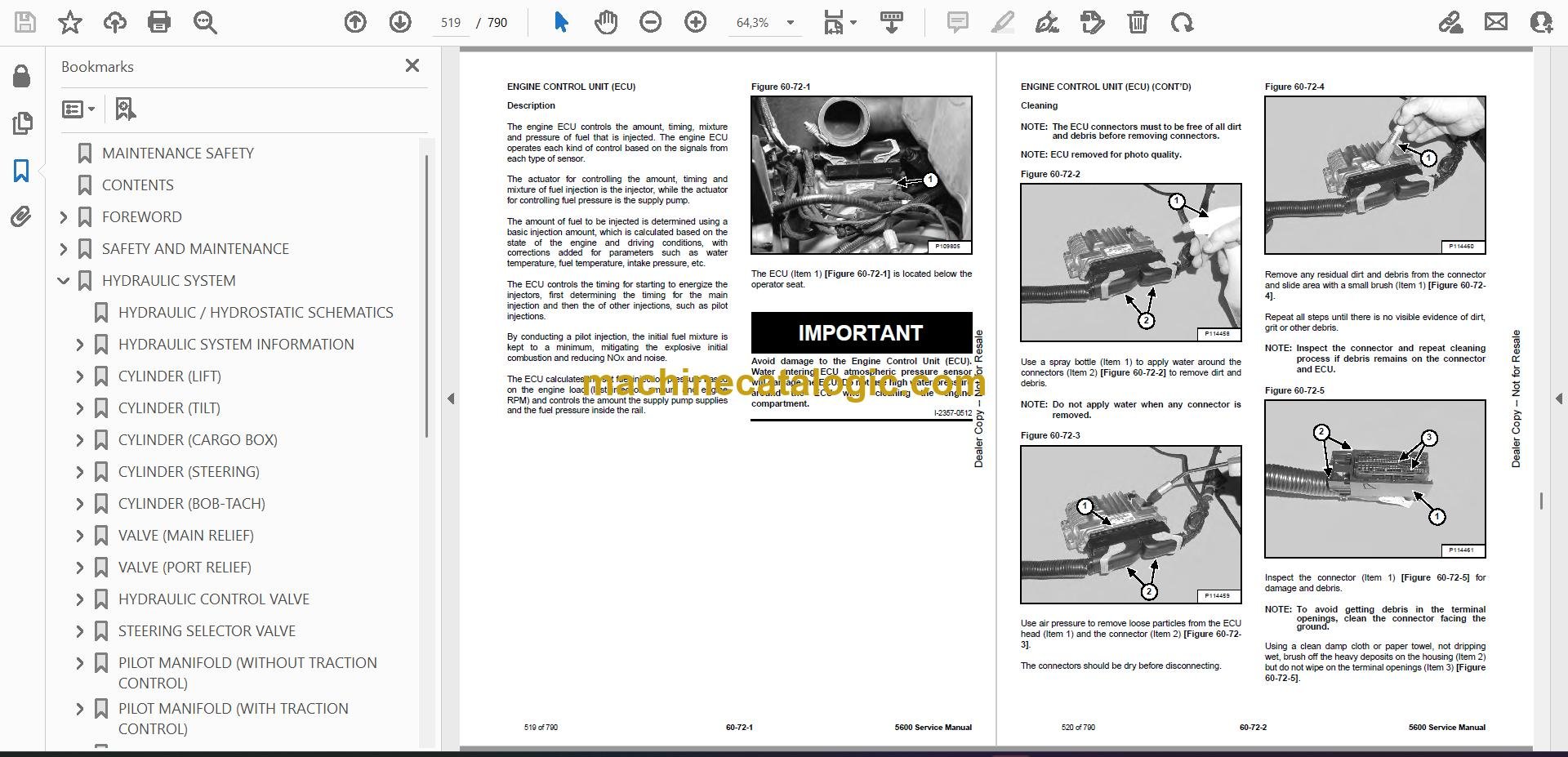
Q: Is this a searchable PDF and are the wiring diagrams readable?

A: Yes, these manuals are normally supplied as a searchable PDF and the wiring diagrams are laid out so you can zoom in and follow circuits clearly on-screen or printed.

Q: How do I know if it fits my exact machine?

A: Check your serial plate. If your 5600 Toolcat serial number falls between AHG811001 and AHG899999, this is the right manual.

Q: Is this the right document if I'm doing full repairs, not just maintenance?

A: Yes. This is the workshop-level service manual, meant for diagnostics and repair, not just routine greasing and fluid checks.

Bottom line: If your 5600 Toolcat's serial is in that AHG811001-AHG899999 range and you're actually turning wrenches on it, this is the manual you want.

📘 Show Index

Table of Contents:

  • MAINTENANCE SAFETY
  • CONTENTS
  • FOREWORD
    • FOREWORD
    • SAFETY INSTRUCTIONS
    • FIRE PREVENTION
      • Maintenance
      • Operation
      • Electrical
      • Hydraulic System
      • Fueling
      • Starting
      • Spark Arrester Exhaust System
      • Welding And Grinding
      • Fire Extinguishers
    • SERIAL NUMBER LOCATIONS
      • Utility Work Machine Serial Number
      • Engine Serial Number
    • DELIVERY REPORT
    • UTILITY WORK MACHINE IDENTIFICATION
  • SAFETY AND MAINTENANCE
    • LIFTING AND BLOCKING THE UTILITY WORK MACHINE
      • Procedure For Jackstand Placement On The Control Arms
      • Procedure For Jackstand Placement On The Frame
    • LIFT ARM SUPPORT DEVICE
      • Installing
      • Removing
    • CARGO BOX SUPPORT DEVICE
      • Installing
      • Removing
      • Raising The Cargo Box When Engine Is Not Running
    • OPERATOR CAB
      • Description
    • TRANSPORTING THE UTILITY WORK MACHINE ON A TRAILER
      • Loading And Unloading
      • Fastening
    • TOWING THE UTILITY WORK MACHINE
      • Procedure
    • REMOTE START TOOL KIT – MEL1563
      • Remote Start Tool – MEL1563
      • Service Tool Harness Control – MEL1565
      • Service Tool Harness Communicator – MEL1566
      • Remote Start Procedure
    • REMOTE START TOOL (SERVICE TOOL) KIT – 7217666
      • Description
      • Remote Start Tool (Service Tool) – 7022042
      • Service Tool Harness – 6689747
      • Computer Service Tool Harness – 6689746
      • Remote Start Procedure
    • SERVICE SCHEDULE
      • Maintenance Intervals
    • AIR CLEANER SERVICE
      • Replacing Filter Elements
    • ENGINE COOLING SYSTEM
      • Checking Level
      • Cleaning
      • Removing And Replacing Coolant
    • FUEL SYSTEM
      • Fuel Specifications
      • Biodiesel Blend Fuel
      • Filling The Fuel Tank
      • Fuel Filter
      • Removing Air From The Fuel System
      • Filling A Portable Fuel Container
    • ENGINE LUBRICATION SYSTEM
      • Checking And Adding Engine Oil
      • Engine Oil Chart
      • Removing And Replacing Oil And Filter
    • HYDRAULIC / HYDROSTATIC SYSTEM
      • Checking Fluid
      • Hydraulic / Hydrostatic Fluid Chart
      • Adding Fluid
      • Alternate Fill Procedure
      • Removing And Replacing Hydraulic / Hydrostatic And Case Drain Filters
      • Removing And Replacing Hydraulic Fluid
      • Breather Cap
    • TRANSAXLE (FRONT AND REAR)
      • Checking And Adding Lubricant
      • Removing And Replacing Lubricant
    • BOB-TACH (HAND LEVER)
      • Inspection And Maintenance
    • BOB-TACH (POWER)
      • Inspection And Maintenance
    • LUBRICATING THE UTILITY WORK MACHINE
      • Lubrication Locations
    • TIRE MAINTENANCE
      • Wheel Nuts
      • Rotating
      • Mounting
    • PIVOT PINS
      • Inspection And Maintenance
    • UTILITY WORK MACHINE STORAGE AND RETURN TO SERVICE
      • Storage
      • Return To Service
    • STOPPING THE ENGINE AND LEAVING THE UTILITY WORK MACHINE
      • Procedure
      • Emergency Exit (When Equipped With Cab)
    • SEAT BELT
      • Inspection And Maintenance
  • HYDRAULIC SYSTEM
    • HYDRAULIC / HYDROSTATIC SCHEMATICS
    • HYDRAULIC SYSTEM INFORMATION
      • Glossary Of Hydraulic / Hydrostatic Symbols
      • Troubleshooting
    • CYLINDER (LIFT)
      • Testing
      • Removal And Installation
      • Parts Identification
      • Disassembly
      • Assembly
    • CYLINDER (TILT)
      • Testing
      • Removal And Installation
      • Parts Identification
      • Disassembly
      • Assembly
    • CYLINDER (CARGO BOX)
      • Testing
      • Removal And Installation (Left Side)
      • Removal And Installation (Right Side)
      • Parts Identification
      • Disassembly
      • Assembly
    • CYLINDER (STEERING)
      • Testing (Rear)
      • Testing (Front)
      • Removal And Installation (Rear)
      • Removal And Installation (Front)
      • Parts Identification
      • Disassembly And Assembly
    • CYLINDER (BOB-TACH)
      • Testing
      • Removal And Installation
      • Parts Identification
      • Disassembly
      • Assembly
    • VALVE (MAIN RELIEF)
      • Description
      • Auxiliary Main Relief Valve Testing
      • Auxiliary Main Relief Valve Removal And Installation
      • Lift, Tilt And Cargo Box Main Relief Valve Testing
      • Lift, Tilt And Cargo Box Main Relief Valve Removal And Installation
    • VALVE (PORT RELIEF)
      • Description
      • Lift Port Relief Valve Testing (Base End)
      • Lift Port Relief Valve Testing (Rod End)
      • Tilt Port Relief Valve Testing
    • HYDRAULIC CONTROL VALVE
      • Description
      • Removal And Installation
      • Identification Chart
      • Disassembly
      • End Valve Section Disassembly And Assembly
      • Box Valve Section Disassembly And Assembly
      • Lift Valve Section Disassembly And Assembly
      • Tilt Valve Section Disassembly And Assembly
      • Mid Inlet / High Flow Valve Section Disassembly And Assembly
      • Auxiliary Valve Section Disassembly And Assembly
      • Assembly
    • STEERING SELECTOR VALVE
      • Description
      • Removal And Installation
      • Disassembly And Assembly
    • PILOT MANIFOLD (WITHOUT TRACTION CONTROL)
      • Description
      • Removal And Installation
      • Parts Identification
      • Disassembly And Assembly
    • PILOT MANIFOLD (WITH TRACTION CONTROL)
      • Description
      • Removal And Installation
      • Parts Identification
      • Disassembly And Assembly
    • LIFT ARM (BYPASS)
      • Description
      • Testing
    • HYDRAULIC PUMP
      • Description
      • Auxiliary Section Testing
      • Lift, Tilt And Cargo Box Section Testing
      • Steering And Cooling Fan Section Testing
      • Removal And Installation
      • Parts Identification
      • Disassembly And Assembly
    • POWER STEERING PUMP
      • Description
      • Removal And Installation
      • Disassembly And Assembly
    • HYDRAULIC / HYDROSTATIC FILTER
      • Description
      • Housing Removal And Installation
      • Case Drain Housing Removal And Installation
    • CONTROL JOYSTICK
      • Description
      • Handle Removal And Installation
    • HYDRAULIC FLUID RESERVOIR
      • Description
      • Removal And Installation
      • Hydraulic Fluid Screen
    • OIL COOLER / RADIATOR
      • Description
      • Removal And Installation
    • AUXILIARY HYDRAULIC COUPLER BLOCK
      • Description
      • Removal And Installation
      • Disassembly And Assembly (FFI/FI)
      • Disassembly And Assembly (FFH/FH)
    • REMOTE HYDRAULICS DIVERTER VALVE
      • Description
      • Removal And Installation
      • Disassembly And Assembly
    • POWER BOB-TACH BLOCK
      • Description
      • Removal And Installation
      • Disassembly And Assembly
    • DIVERTER VALVE (REAR AUXILIARY)
      • Description
      • Solenoid Testing
      • Removal And Installation
      • Disassembly And Assembly
  • HYDROSTATIC SYSTEM
    • HYDROSTATIC SYSTEM INFORMATION
      • Troubleshooting
      • Description
    • HYDROSTATIC MOTOR
      • Description
      • Removal And Installation (Front)
      • Removal And Installation (Rear)
      • Parts Identification
      • Disassembly
      • Assembly
    • CHARGE PRESSURE
      • Description
      • Testing
    • HYDROSTATIC PUMP
      • Description
      • Removal And Installation
      • Control Module Removal And Installation
      • Replenishing / High Pressure Relief Valve Removal And Installation
      • Charge Relief Valve Removal And Installation
      • Parts Identification
      • Disassembly And Assembly
      • Mechanical Neutral Adjustment
      • Hydraulic Controller Neutral Adjustment
    • DRIVE BELT
      • Description
      • Exhaust Tube Removal And Installation
      • Shield Removal And Installation
      • Belt Adjusting
      • Belt Replacement
      • Tensioner Pulley Removal And Installation
      • Tensioner Pulley Disassembly
  • DRIVE SYSTEM
    • BRAKE
      • Description
      • Disassembly And Assembly (Front Transaxle)
      • Disassembly And Assembly (Rear Transaxle)
    • TRANSAXLE
      • Description
      • Removal And Installation (Front)
      • Removal And Installation (Rear)
      • Brake Housing Disassembly And Assembly
      • Primary Housing Disassembly And Assembly
    • HUB
      • Description
      • Removal And Installation
    • CV SHAFT
      • Description
      • Removal And Installation (Front)
      • Removal And Installation (Rear)
      • Inner Boot Removal And Installation
      • Outer Boot Removal And Installation
  • MAINFRAME
    • OPERATOR CAB
      • Removal And Installation
    • OPERATOR SEAT
      • Removal And Installation
      • Seat Belt Removal And Installation
      • Seat Pan Removal And Installation
      • Slide Rail Removal And Installation
      • Armrest Bracket Removal And Installation
      • Armrest Removal And Installation
    • PASSENGER SEAT
      • Removal And Installation
      • Seat Belt Removal And Installation
      • Seat Pan Removal And Installation
      • Armrest Removal And Installation
    • BOB-TACH (HAND LEVER)
      • Description
      • Removal And Installation
      • Lever And Wedge Disassembly And Assembly
    • BOB-TACH (POWER)
      • Description
      • Removal And Installation
      • Lever And Wedge Disassembly And Assembly
    • LIFT ARM
      • Removal And Installation
    • CARGO BOX
      • Removal And Installation
    • STEERING COLUMN
      • Removal And Installation
    • FUEL TANK
      • Removal And Installation
      • Fuel Level Sender Removal And Installation
    • DRIVE AND BRAKE PEDALS
      • Description
      • Removal And Installation
      • Drive Pedal Disassembly And Assembly
    • SHOCKS
      • Removal And Installation
    • CONTROL ARMS
      • Removal And Installation (Lower Arm)
      • Removal And Installation (Upper Arm)
      • Inspection
      • Ball Joint Removal And Installation
    • SPINDLE
      • Removal And Installation
    • TIE ROD
      • Description
      • Removal And Installation
      • Toe Adjustment Procedure
    • FLOOR CONSOLE
      • Access Cover Removal And Installation (Side)
      • Access Cover Removal And Installation (Top)
    • CENTER CONSOLE
      • Removal And Installation
    • FENDER
      • Removal And Installation (Front)
      • Removal And Installation (Left Rear)
      • Removal And Installation (Right Rear)
    • WINDOWS
      • Front, Rear And Lower Door Removal And Installation
      • Upper Door Removal And Installation
    • HEADLINER
      • Removal And Installation
  • ELECTRICAL SYSTEM AND ANALYSIS
    • ELECTRICAL SCHEMATICS
    • ELECTRICAL SYSTEM INFORMATION
      • Glossary Of Electrical Symbols
      • Cab Harness Connectors
      • Mainframe Harness Connectors
      • Engine Harness Connectors
      • Description
      • Troubleshooting
      • Fuse And Relay Location – Cab Panel
      • Fuse And Relay Location – Frame Panel
      • Solenoid Testing
    • BATTERY
      • Removal And Installation
      • Servicing
      • Using A Booster Battery (Jump Starting)
    • ALTERNATOR
      • Belt Adjustment
      • Belt Replacement
      • Charging System Inspection
      • Alternator Voltage Testing
      • Low Voltage Testing
      • High Voltage Testing
      • Removal And Installation
      • Parts Identification
    • STARTER
      • Testing
      • Removal And Installation
      • Parts Identification
    • INSTRUMENT PANELS
      • Display Controller Panel
      • Switch Panel
      • Floor Console
      • Center Console
      • Radio
    • LIGHTS
      • Front Removal And Installation
    • BOBCAT CONTROLLER (DISPLAY)
      • Description
      • Connector Identification
      • Removal And Installation
    • BOBCAT CONTROLLER (DRIVE)
      • Description
      • Connector Identification
      • Removal And Installation
    • ENGINE CONTROL UNIT (ECU)
      • Description
      • Cleaning
      • Removal And Installation
    • DIAGNOSTIC SERVICE CODES
      • Description
      • Service Codes List
    • CONTROL PANEL SETUP
      • Enter Setup
      • Two-Speed
      • High Flow
      • Horsepower Management
      • Tire Size
      • Save Setup
      • Exit Setup
    • PASSWORD SETUP (KEYLESS START)
      • Password Description
      • Changing The Owner And Operator Passwords
      • Password Lockout Feature
    • TOOLCAT INTERLOCK CONTROL SYSTEM (TICS™)
      • Description
      • Inspecting The TICS™
      • Maintaining The TICS™
      • Lift Arm Bypass Procedure
      • Inspecting
    • ARMREST SENSOR
      • Description
      • Removal And Installation
    • SPEED SENSORS
      • Description
      • Removal And Installation (Front Transaxle)
    • WHEEL POSITION SENSORS
      • Description
      • Removal And Installation (Front)
      • Removal And Installation (Rear)
      • Adjusting (In The Machine)
      • Adjusting (Out Of The Machine)
    • SERVICE PC (LAPTOP COMPUTER)
      • Connecting Remote Start Tool
      • Connecting Remote Start Tool (Service Tool)
    • CALIBRATION
      • Description
      • Throttle Position Sensor Calibration
      • Drive System Calibration
      • Brake Pedal Calibration
      • Travel Pedal Calibration
    • TRAVEL DIRECTION CONTROL LEVER
      • Description
      • Removal And Installation
    • ELECTRIC COOLING FAN
      • Description
      • Removal And Installation
    • MAINTENANCE CLOCK
      • Description
      • Setup
      • Reset
    • BACK-UP ALARM SYSTEM
      • Description
      • Inspecting
    • FRONT HORN
      • Description
      • Removal And Installation
      • Troubleshooting
    • TRACTION CONTROL
      • Description
      • Operation
      • Removal And Installation
    • ELECTRICAL / HYDRAULIC CONTROLS
      • Description
      • Identification Chart ACD Group 0
      • Identification Chart ACD Group 1
      • Identification Chart ACD Group 2
      • Identification Chart ACD Group 3
  • ENGINE SERVICE
    • ENGINE INFORMATION
      • Description
      • Specifications
      • Sensor Location
      • Torque Values
      • Troubleshooting
      • Engine Removal And Installation
      • Engine Mount Replacement
      • Compression – Testing
      • Injector Signal – Testing
      • Injector Signal – Testing (In-Line)
    • ENGINE SPEED CONTROL
      • Removal And Installation
      • Disassembly And Assembly
    • DIESEL OXIDATION CATALYST (DOC)
      • Removal And Installation
    • AIR CLEANER
      • Housing Removal And Installation
    • ENGINE COOLING SYSTEM
      • Radiator / Oil Cooler Removal And Installation
      • Hydraulic Fan Description
      • Hydraulic Fan Removal And Installation
      • Hydraulic Fan Disassembly And Assembly
      • Water Pump Removal And Installation
      • Thermostat Housing Removal And Installation
      • Testing The Thermostat
    • LUBRICATION SYSTEM
      • Description
      • Oil Pan Removal And Installation
      • Oil Pump Removal And Installation
      • Oil Pump Relief Valve Description
      • Oil Pump Relief Valve Removal And Installation
      • Oil Cooler Removal And Installation
      • Oil Filter Head Removal And Installation
      • Oil Cooler Bypass Description
      • Oil Cooler Bypass Removal And Installation
    • FUEL SYSTEM
      • Description
      • High Pressure Pump Removal And Installation
      • Fuel Temperature Sensor Removal And Installation
      • Fuel Cooler Removal And Installation
      • Fuel Cooler Bypass Valve Removal And Installation
      • Fuel Recirculation Valve Removal And Installation
      • Fuel Rail Assembly Removal And Installation
      • Fuel Injector Removal And Installation
      • Removing Air From The Fuel System
    • CYLINDER HEAD
      • Glow Plugs Testing
      • Glow Plugs Removal And Installation
      • Valve Clearance Adjustment
      • Cylinder Head Removal And Installation
      • Cylinder Head Disassembly And Assembly
      • Cylinder Head Inspection
      • Cylinder Head Top Clearance
      • Valve Step Height
      • Valve Stem Height
      • Valve Guide
      • Valve
      • Valve Spring
      • Rocker Arm Shaft Disassembly And Assembly
      • Rocker Arm Shaft Inspection
      • Push Rod Inspection
    • CRANKSHAFT AND PISTONS
      • Piston And Connecting Rod Removal And Installation
      • Piston And Connecting Rod Inspection
      • Crankshaft Removal And Installation
      • Cylinder Block Inspection
      • Crankshaft Inspection
      • Engine Component Class
    • CAMSHAFT
      • Removal And Installation
      • Inspecting
    • GEARCASE
      • Gearcase Cover Removal And Installation
      • Gear Backlash
      • Gear Timing
      • Idle Gear Removal And Installation
    • TURBOCHARGER
      • Description
      • Removal And Installation
      • Inspection
    • FLYWHEEL AND HOUSING
      • Flywheel Removal And Installation
      • Ring Gear Removal And Installation
      • Housing Removal And Installation
    • EXHAUST GAS RECIRCULATION (EGR) SYSTEM
      • Description
      • Removal And Installation
      • Disassembly And Assembly
  • HEATING, VENTILATION AND AIR CONDITIONING (HVAC)
    • AIR CONDITIONING SYSTEM FLOW
      • Description
      • A/C System Diagram
      • Components
      • Safety Equipment
    • REGULAR MAINTENANCE
      • Filter Elements Removal And Installation
      • Compressor Drive Belt Inspection
      • Condenser
      • Air Conditioning Service Chart
      • A/C Evaporator Coil
    • TROUBLESHOOTING
      • Blower Motor Does Not Operate
      • Blower Motor Operates Normally But Air Flow Is Insufficient
      • Insufficient Cooling Although Air Flow And Compressor Operation Are Normal
      • The Compressor Does Not Operate At All Or Operates Improperly
      • Gauge Pressure Related Troubleshooting
      • Temperature / Pressure Chart
      • Poor A/C Performance
      • HVAC Repair And Leaks
      • Electrical System
      • Engine Coolant Bypassing The Heater Valve
      • Heater Valve Not Opening Or Closing
    • SYSTEM CHARGING AND RECLAMATION
      • Refrigerant Identification
      • Reclamation And Charging With Recovery / Charging Unit
      • Charging With A Manifold Gauge Set
    • COMPRESSOR
      • Belt Adjustment
      • Belt Replacement
      • Removal And Installation
      • Oil
      • Oil Check
    • CONDENSER
      • Removal And Installation
    • RECEIVER / DRIER
      • Receiver / Drier Removal And Installation
      • Pressure Relief Valve Removal And Installation
      • Pressure Switch Removal And Installation
    • EVAPORATOR / HEATER UNIT
      • Removal And Installation
    • THERMOSTAT
      • Description
      • Removal And Installation
    • EXPANSION VALVE
      • Removal And Installation
    • EVAPORATOR COIL
      • Removal And Installation
    • HEATER COIL
      • Removal And Installation With A/C
    • BLOWER FAN
      • Removal And Installation
    • HEATER VALVE
      • Removal And Installation
      • Disassembly And Assembly
  • SPECIFICATIONS
    • (5600) UTILITY WORK MACHINE SPECIFICATIONS
      • Dimensions (With 27 Inch Tires)
      • Dimensions (With 29 Inch Tires)
      • Performance
      • Controls
      • Engine
      • Hydraulic System
      • Electrical
      • Drive System
      • Capacities
      • Tires
    • TECHNICAL SERVICE GUIDE SPECIFICATIONS
      • Engine
      • Engine Torques
      • Cooling System
      • Loader Torques
      • Hydraulic / Hydrostatic System
      • Fuel Consumption
    • TORQUE SPECIFICATIONS FOR BOLTS
      • Torque For General SAE Bolts
      • Torque For General Metric Bolts
    • HYDRAULIC CONNECTION SPECIFICATIONS
      • O-ring Face Seal Connection
      • Straight Thread O-ring Fitting
      • Tubelines And Hoses
      • Flare Fitting
      • O-ring Flare Fitting
      • Port Seal Fitting
      • Quick-Lok™ Fitting
    • HYDRAULIC / HYDROSTATIC FLUID SPECIFICATIONS
      • Specifications
    • CONVERSIONS
      • Decimal And Millimeter Equivalent Chart
      • U.S. To Metric Conversion Chart
    • SERVICE TOOLS REQUIRED
      • Remote Start Tools
      • Hydraulic Tools
      • Mainframe And Drive Tools
      • Electrical Tools
      • Engine Tools
      • HVAC Tools
  • ALPHABETICAL INDEX

Bobcat Software

Bobcat PDF Manuals

Related Manuals

0
    0
    Your Cart
    Your cart is emptyReturn to Shop