$ 0
0
$ 0
0

Bobcat E50 Excavator Service Manual (SN B4GP11001-B4GP99999)

Format: PDF (Printable Document)

File Language: English

File Pages: 919

File Size: 28.62 MB (Speed Download Link)

Brand: Bobcat

Model: E50 Excavator

Book No: 7336771

Serial No: SN B4GP11001-B4GP99999

Type of Document: Service Manual

Categories: ,

$ 45

Share:

Bobcat E50 Excavator Service Manual (SN B4GP11001-B4GP99999)

The E50 is a mid-size mini ex that spends its life trenching, digging footings, loading trucks, and running augers. When something quits, the guy who grabs the service manual is the one actually fixing it, not just running it. Around my shop that means chasing down hydraulic issues, wiring problems, or tearing into the upper structure without guessing and making downtime worse.

What this manual helps you do

  • Diagnose hydraulic problems, check pressures, and trace leaks on the E50's excavator circuits and auxiliary lines
  • Troubleshoot electrical faults, follow wiring diagrams, and track down bad sensors, switches, or relays
  • Rebuild and replace components like cylinders, drive motors, swing gear, and final drives with proper sequences and specs
  • Set and verify adjustments on controls, pilot lines, and travel functions after repairs so the machine runs straight and smooth
  • Follow step-by-step removal and install procedures for engine, pumps, valves, and major assemblies on this exact E50 series

Who this is for

This is for a small contractor, owner-operator, field tech, or shop mechanic who is actually turning wrenches on a Bobcat E50 with serial numbers in the B4GP11001-B4GP99999 range. If you just want basic operating tips, safety info, or service intervals, you want the operator's handbook instead, not this manual.

FAQ

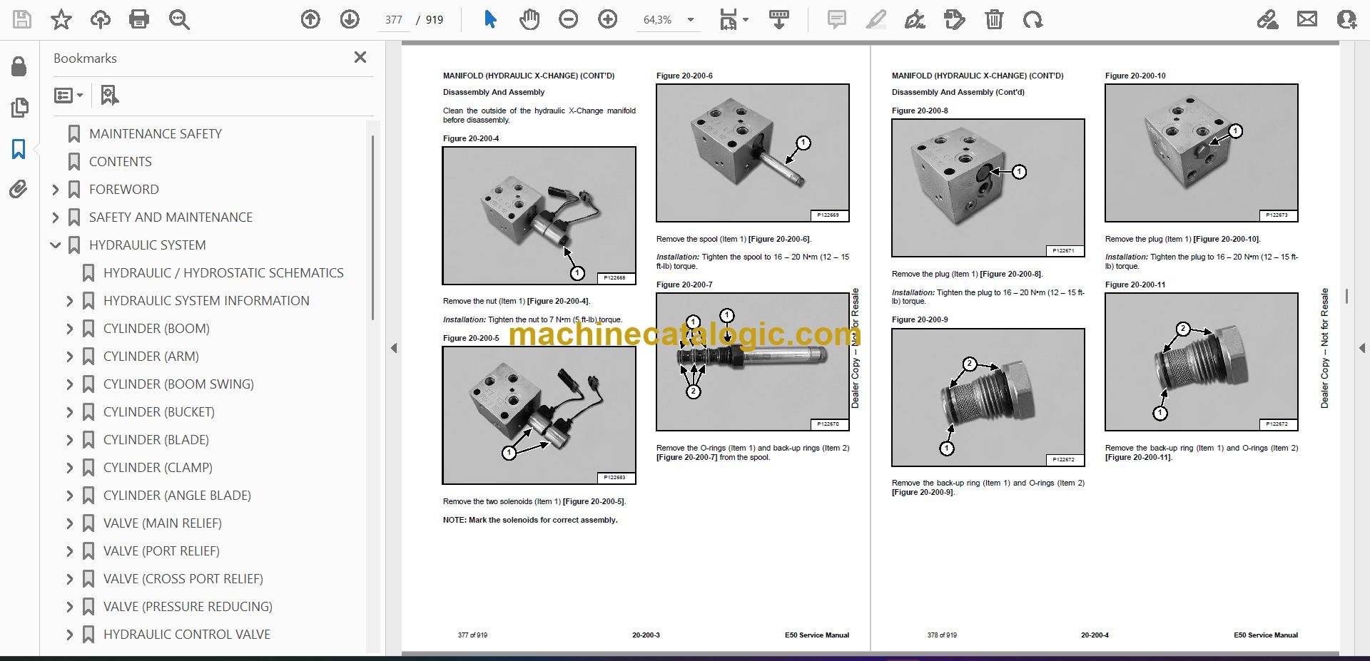
Q: Is this a searchable PDF and are the wiring diagrams readable?

A: Yes, these are normally searchable PDFs and the wiring diagrams are laid out so you can zoom in and read pin numbers and wire colors.

Q: How do I know if it fits my E50?

A: Check your serial plate. If your E50 serial number falls between B4GP11001 and B4GP99999, this is the right manual series.

Q: Is this what I need for real repairs, not just maintenance?

A: Yes, this is the workshop service manual, the one you use for diagnostics, teardown, and reassembly, not just fluid changes.

Bottom line: If your E50's serial number is in that B4GP range and you're planning to actually fix or rebuild things, this is the manual you want. If your serial is outside that range, skip it.

📘 Show Index

Table of Contents:

  • MAINTENANCE SAFETY
  • CONTENTS
  • FOREWORD
    • FOREWORD
    • SAFETY INSTRUCTIONS
    • FIRE PREVENTION
      • Maintenance
      • Operation
      • Electrical
      • Hydraulic System
      • Fueling
      • Starting
      • Spark Arrester Exhaust System
      • Welding And Grinding
      • Fire Extinguishers
    • SERIAL NUMBER LOCATIONS
      • Excavator Serial Number
      • Engine Serial Number
    • DELIVERY REPORT
    • EXCAVATOR IDENTIFICATION
  • SAFETY AND MAINTENANCE
    • LIFTING AND BLOCKING THE EXCAVATOR
      • Procedure
    • LIFTING THE EXCAVATOR
      • Procedure
    • OPERATOR CAB (ROPS / TOPS / FOPS)
      • Description
      • Cab Door
      • Front Window
      • Front Wiper
      • Window Washer Reservoir
      • Right Side Windows
    • OPERATOR CANOPY (ROPS / TOPS / FOPS)
      • Description
    • TRANSPORTING THE EXCAVATOR ON A TRAILER
      • Loading And Unloading
      • Fastening
    • TAILGATE
      • Opening And Closing
      • Adjusting The Latch
    • RIGHT SIDE COVER
      • Opening And Closing
    • SERVICE SCHEDULE
      • Maintenance Intervals
      • Service Schedule
    • AIR CLEANER SERVICE
      • Replacing The Filter Elements
    • CAB FILTERS
      • Cleaning And Maintenance
    • ENGINE COOLING SYSTEM
      • Cleaning
      • Checking Level
      • Removing And Replacing Coolant (Cab Models)
      • Removing And Replacing Coolant (Canopy Models)
    • FUEL SYSTEM
      • Fuel Specifications
      • Biodiesel Blend Fuel
      • Filling The Fuel Tank
      • Fuel Filters
      • Draining The Fuel Tank
      • Replacing The Fuel Pre-Filter
      • Replacing The Fuel Tank Vent Filter
    • ENGINE LUBRICATION SYSTEM
      • Checking And Adding Engine Oil
      • Engine Oil Chart
      • Removing And Replacing Oil And Filter
    • HYDRAULIC SYSTEM
      • Checking And Adding Hydraulic Oil
      • Hydraulic / Hydrostatic Fluid Chart
      • Removing And Replacing The Hydraulic Filters
      • Removing And Replacing The Hydraulic Fluid
    • MACHINE LUBRICATION
      • Grease Fitting Locations
    • PIVOT PINS
      • Inspection And Maintenance
    • TRAVEL MOTOR
      • Checking And Adding Oil
      • Removing And Replacing Oil
    • EMERGENCY EXIT
      • Right Side Rear Window
      • Front Window
    • SEAT BELT
      • Inspection And Maintenance
    • CONTROL CONSOLE LOCKOUTS
      • Inspection And Maintenance
    • TOWING THE EXCAVATOR
      • Procedure
    • REMOTE START TOOL (SERVICE TOOL) KIT – 7217666
      • Description
      • Remote Start Tool (Service Tool) – 7022042
      • Excavator Service Tool Harness – 6689747
      • Computer Service Tool Harness – 6689746
  • HYDRAULIC SYSTEM
    • HYDRAULIC / HYDROSTATIC SCHEMATICS
    • HYDRAULIC SYSTEM INFORMATION
      • Glossary Of Hydraulic / Hydrostatic Symbols
      • Troubleshooting The Hydraulic Circuit
      • Troubleshooting The Cylinder Circuit
      • Troubleshooting The Swing (Upperstructure Slew) Circuit
      • Troubleshooting The Travel Circuit
    • CYLINDER (BOOM)
      • Testing
      • Removal And Installation
      • Parts Identification
      • Disassembly
      • Assembly
    • CYLINDER (ARM)
      • Testing
      • Removal And Installation
      • Parts Identification
      • Disassembly
      • Assembly
    • CYLINDER (BOOM SWING)
      • Testing
      • Removal And Installation
      • Parts Identification
      • Disassembly
      • Assembly
    • CYLINDER (BUCKET)
      • Testing
      • Removal And Installation
      • Parts Identification
      • Disassembly
      • Assembly
    • CYLINDER (BLADE)
      • Testing
      • Removal And Installation
      • Parts Identification
      • Disassembly
      • Assembly
    • CYLINDER (CLAMP)
      • Testing
      • Removal And Installation
      • Parts Identification
      • Disassembly
      • Assembly
    • CYLINDER (ANGLE BLADE)
      • Testing
      • Removal And Installation
      • Parts Identification
      • Disassembly
      • Assembly
    • VALVE (MAIN RELIEF)
      • Testing And Adjusting
    • VALVE (PORT RELIEF)
      • Testing And Adjusting
    • VALVE (CROSS PORT RELIEF)
      • Testing And Adjusting
      • Removal And Installation
    • VALVE (PRESSURE REDUCING)
      • Testing And Adjusting
    • HYDRAULIC CONTROL VALVE
      • Description
      • Removal And Installation
      • Parts Identification
      • Disassembly And Assembly
      • Inlet Valve Section Disassembly And Assembly
      • Boom Swing Valve Section Disassembly And Assembly
      • Slew Valve Section Disassembly And Assembly
      • Blade Valve Section Disassembly And Assembly
      • Right And Left Travel Valve Section Disassembly And Assembly
      • Angle Blade Valve Section Disassembly And Assembly
      • Boom, Auxiliary, Arm, And Bucket Valve Section Disassembly And Assembly
    • HYDRAULIC PUMP
      • Hydraulic Pump Work Sheet
      • Pump Testing
      • Removal And Installation
      • Coupler Removal And Installation
      • Hydraulic Pump Startup
      • Torque Limiter Assembly Parts Identification
      • Torque Limiter Assembly Removal And Installation
      • Torque Limiter Valve Assembly Disassembly And Assembly
      • Pump Control Parts Identification
      • Pump Control Removal And Installation
      • Pump Control Disassembly And Assembly
    • MANIFOLD ASSEMBLY / ACCUMULATOR (WITHOUT ANGLE BLADE)
      • Description
      • Removal And Installation
      • Parts Identification
      • Disassembly And Assembly
    • MANIFOLD ASSEMBLY / ACCUMULATOR (WITH ANGLE BLADE)
      • Description
      • Removal And Installation
      • Parts Identification
      • Disassembly And Assembly
    • TRAVEL MOTOR
      • Removal And Installation
      • Parts Identification Hydraulic Motor
      • Parts Identification Gear Reduction Hub
      • Disassembly
      • Assembly
    • SWIVEL JOINT
      • Removal And Installation
      • Parts Identification Straight Blade Swivel
      • Disassembly And Assembly
    • SWIVEL JOINT (WITH ANGLE BLADE)
      • Removal And Installation
      • Parts Identification Angle Blade Swivel
      • Disassembly And Assembly
    • SWING MOTOR
      • Removal And Installation
      • Parts Identification
      • Disassembly And Assembly
    • SWING MOTOR (DRIVE CARRIER)
      • Removal And Installation
      • Parts Identification
      • Disassembly And Assembly
    • CONTROL PATTERN SELECTOR VALVE
      • Removal And Installation
      • Parts Identification
      • Disassembly And Assembly
    • RIGHT CONTROL LEVER (JOYSTICK)
      • Testing
      • Handle Removal And Installation
      • Joystick Assembly Removal And Installation
      • Parts Identification
      • Disassembly
      • Assembly
    • LEFT CONTROL LEVER (JOYSTICK)
      • Testing
      • Handle Removal And Installation
      • Joystick Assembly Removal And Installation
      • Parts Identification
      • Disassembly
      • Assembly
    • HYDRAULIC FILTER MOUNT
      • Removal And Installation
    • HYDRAULIC RESERVOIR
      • Removal And Installation
    • OIL COOLER
      • Description
      • Removal And Installation
    • BLADE CONTROL LEVER
      • Handle Removal And Installation
      • Removal And Installation
      • Parts Identification
      • Disassembly And Assembly
    • CASE DRAIN FILTER MOUNT
      • Removal And Installation
    • TRAVEL CONTROL VALVE
      • Removal And Installation
      • Parts Identification
      • Disassembly And Assembly
    • REMOVING AIR FROM THE HYDRAULIC SYSTEM
      • Procedure
    • MANIFOLD (HYDRAULIC X-CHANGE)
      • Removal And Installation
      • Parts Identification
      • Disassembly And Assembly
    • MANIFOLD (PIN GRABBER)
      • Removal And Installation
      • Parts Identification
      • Disassembly And Assembly
    • SECONDARY AUXILIARY VALVE
      • Removal And Installation
      • Parts Identification
      • Disassembly And Assembly
    • VALVE (BOOM LOCK)
      • Removal And Installation
    • VALVE (ARM LOCK)
      • Removal And Installation
  • UNDERCARRIAGE
    • BLADE
      • Removal And Installation
    • BLADE (ANGLE)
      • Removal And Installation
      • Cutting Edge Removal And Installation
    • TRACK UNDERCARRIAGE COMPONENTS (RUBBER TRACK)
      • Description
      • Track Lug Height
      • Checking / Adjusting Tension
      • Track Removal And Installation
      • Idler Removal And Installation
      • Idler Parts Identification
      • Idler Disassembly
      • Idler Assembly
      • Track Tensioner Removal And Installation
      • Track Tensioner Parts Identification
      • Track Tensioner Disassembly And Assembly
      • Roller Removal And Installation
      • Sprocket Removal And Installation
    • TRACK UNDERCARRIAGE COMPONENTS (STEEL TRACK)
      • Description
      • Checking / Adjusting Tension
      • Track Removal
      • Track Installation
      • Idler Removal And Installation
      • Idler Parts Identification
      • Idler Disassembly
      • Idler Assembly
      • Track Tensioner Removal And Installation
      • Track Tensioner Parts Identification
      • Track Tensioner Disassembly And Assembly
      • Roller Removal And Installation
      • Sprocket Removal And Installation
      • Guide Plate Removal And Installation
    • TRACK MAINTENANCE
      • Track Damage Identification
    • SWING CIRCLE GEAR
      • Swing Bearing Removal
      • Swing Bearing Installation
  • UPPERSTRUCTURE AND SWING SECTION
    • UPPERSTRUCTURE
      • Removal
      • Installation
    • ROPS CANOPY
      • Removal And Installation
    • CAB
      • Removal And Installation
      • Door Removal And Installation
      • Door Latch Removal And Installation
      • Hold Open Latch Removal And Installation
      • Front Window Removal And Installation
      • Front Window Disassembly And Assembly
      • Front Window Adjustment
      • Right Side Rear Sliding Window Removal And Installation
      • Glass Removal
    • SEAT
      • Removal And Installation
    • RIGHT CONSOLE
      • Console Cover Removal And Installation
    • LEFT CONSOLE
      • Lower Console Cover Removal And Installation
      • Upper Console Cover Removal And Installation
      • Compression Spring Removal And Installation
      • Lock Lever Removal And Installation
      • Console Removal And Installation
    • LEFT UPPERSTRUCTURE COVER
      • Removal And Installation
    • RIGHT UPPERSTRUCTURE COVER
      • Removal And Installation
    • COUNTERWEIGHT
      • Removal And Installation
      • Add-On Counterweight Removal And Installation
    • TRAVEL LEVERS AND PEDALS
      • Removal And Installation
      • Disassembly And Assembly
    • FLOORPLATE
      • Removal And Installation
    • FUEL TANK
      • Removal And Installation
    • HORN
      • Removal And Installation
    • SWING FRAME
      • Removal And Installation
      • Boom Swing Frame Hose Routing
      • Bushing Removal
      • Bushing Installation
    • BOOM
      • Removal And Installation
    • STANDARD AND LONG ARM
      • Removal And Installation
      • Arm To Boom Bushing Removal And Installation
      • Arm To Bucket And Bucket Link Bushing Removal And Installation
    • BUCKET
      • Bucket Teeth Removal And Installation
      • Bucket Side Cutting Edge Removal And Installation
    • CLAMP
      • Removal And Installation
    • TAILGATE
      • Removal And Installation
      • Latch Removal And Installation
    • X-CHANGE
      • Removal And Installation
      • Disassembly
      • Assembly
    • X-CHANGE (HYDRAULIC)
      • Removal And Installation
      • Parts Identification
      • Disassembly
      • Assembly
    • QUICK COUPLER (KLAC™ SYSTEM)
      • Troubleshooting
      • Daily Inspection
      • Removal And Installation
      • Parts Identification
      • Disassembly
      • Assembly
    • QUICK COUPLER (GERMAN STYLE)
      • Troubleshooting
      • Daily Inspection
      • Removal (MS03 And MS08)
      • Installation (MS03 And MS08)
      • Parts Identification (MS03)
      • Disassembly And Assembly (MS03)
      • Parts Identification (MS08)
      • Disassembly (MS08)
      • Assembly (MS08)
    • QUICK COUPLER (PIN GRABBER)
      • Troubleshooting
      • Daily Inspection
      • Removal And Installation
      • Parts Identification
      • Disassembly And Assembly
    • RIGHT SIDE COVER
      • Removal And Installation
      • Latch Removal And Installation
    • TOOL BOX
      • Removal And Installation
    • LEFT SIDE GRILLE
      • Removal And Installation
    • LEFT SIDE PANEL
      • Removal And Installation
    • RIGHT SIDE GRILLE
      • Removal And Installation
  • ELECTRICAL SYSTEM AND ANALYSIS
    • ELECTRICAL SCHEMATICS
    • ELECTRICAL SYSTEM INFORMATION
      • Troubleshooting Chart
      • Description
      • Fuse And Relay Location / Identification
    • BATTERY
      • Servicing
      • Maintaining Battery Charge Level
      • Battery Service During Machine Storage
      • Battery Testing
      • Battery Charging
      • Removing And Installing
      • Using A Booster Battery (Jump Starting)
    • ALTERNATOR
      • Belt Adjustment
      • Belt Replacement
      • Charging System Inspection
      • Alternator Voltage Testing
      • Low Voltage Testing
      • High Voltage Testing
      • Removal And Installation
      • Parts Identification
    • STARTER
      • Testing
      • Removal And Installation
      • Parts Identification
    • LIGHTS
      • Removal And Installation
      • Boom Light Removal And Installation
      • Boom Light Bulb Replacement
    • MAGNETIC LOCKOUT SENSOR
      • Removal And Installation
    • FUEL LEVEL SENDER
      • Removal And Installation
      • Testing
    • DIAGNOSTIC SERVICE CODES
      • Viewing Service Codes
      • Service Codes List
    • CONTROL PANEL SETUP
      • Panel Setup (Touch Display)
    • STANDARD DISPLAY
      • Removal And Installation
    • TOUCH DISPLAY
      • Removal And Installation
      • Controller Display Removal And Installation
    • CONTROLLER (GATEWAY AND AUXILIARY)
      • Description
      • Gateway Controller Removal And Installation
      • Auxiliary Controller Removal And Installation
    • ENGINE CONTROL UNIT (ECU)
      • Description
      • Cleaning
      • Removal And Installation
    • KEY SWITCH
      • Removal And Installation
    • WIPER MOTOR
      • Removal And Installation
    • MOTION ALARM SYSTEM
      • Description
      • Inspecting
      • Switch Removal And Installation
    • SERVICE PC (LAPTOP COMPUTER)
      • Connecting The Remote Start Tool
      • Connecting Remote Start Tool (Service Tool)
    • SHUT-OFF SWITCH (IF EQUIPPED)
      • Description
      • Removal And Installation
    • TRAVEL MOTOR AUTO-SHIFT
      • Auto-Shift Drive System
      • Troubleshooting
    • AUTO IDLE PRESSURE SENSOR
      • Description
      • Removal And Installation
    • BOBCAT MACHINE IQ WIRELESS COMMUNICATIONS
      • Description
  • ENGINE SERVICE
    • ENGINE INFORMATION
      • Description
      • Specifications
      • Sensor Location
      • Torque Values
      • Troubleshooting
      • Engine Removal And Installation
      • Compression – Testing (Using Glow Plug Compression Adapter)
      • Compression – Testing (Using Injector Compression Adapter)
      • Injector Signal – Testing
      • Injector Signal – Testing (In-Line)
    • DIESEL OXIDATION CATALYST (DOC)
      • Removal And Installation
    • AIR CLEANER
      • Housing Removal And Installation
    • ENGINE COOLING SYSTEM
      • Description
      • Radiator Cooling Package Removal And Installation
      • Fan Removal And Installation
      • Water Pump Removal And Installation
      • Thermostat Housing Removal And Installation
      • Testing The Thermostat
    • LUBRICATION SYSTEM
      • Description
      • Oil Pan Removal And Installation
      • Oil Pump Removal And Installation
      • Oil Pump Relief Valve Description
      • Oil Pump Relief Valve Removal And Installation
      • Oil Cooler / Oil Filter Module Removal And Installation
      • Oil Cooler / Oil Filter Module Disassembly and Assembly
    • FUEL SYSTEM
      • Description
      • Transfer Pump / High Pressure Pump Removal And Installation
      • Fuel Injector Removal And Installation
      • Lift Pump Removal And Installation
      • Fuel Filter Housing Removal And Installation
    • CYLINDER HEAD
      • Glow Plugs Testing
      • Glow Plug Removal And Installation
      • Cylinder Head Removal And Installation
      • Cylinder Head Disassembly And Assembly
      • Cylinder Head Inspection
      • Cylinder Head Top Clearance
      • Valve Step Height
      • Valve Stem Height
      • Valve Guide
      • Valve
      • Valve Spring
      • Rocker Arm Shaft Disassembly And Assembly
      • Rocker Arm Shaft Inspection
      • Push Rod Inspection
    • CRANKSHAFT AND PISTONS
      • Piston And Connecting Rod Removal And Installation
      • Piston And Connecting Rod Inspection
      • Crankshaft Removal And Installation
      • Cylinder Block Inspection
      • Crankshaft Inspection
      • Connecting Rod Inspection
      • Engine Component Class
    • CAMSHAFT
      • Removal And Installation
      • Inspecting
    • GEARCASE
      • Gearcase Cover Removal And Installation
      • Gear Backlash
      • Gear Timing
      • Idle Gear Removal And Installation
      • Idle Gear Inspection
    • TURBOCHARGER
      • Description
      • Removal And Installation
      • Inspection
    • FLYWHEEL AND HOUSING
      • Hydraulic Pump Coupler Removal And Installation
      • Flywheel Removal And Installation
      • Ring Gear Removal And Installation
    • EXHAUST GAS RECIRCULATION (EGR) SYSTEM
      • EGR Valve Removal And Installation
      • EGR Cooler Removal And Installation
    • INTERCOOLER
      • Description
      • Removal And Installation
  • HEATING, VENTILATION AND AIR CONDITIONING
    • AIR CONDITIONING SYSTEM FLOW
      • Description
      • Chart
      • Components
      • Safety Equipment
    • REGULAR MAINTENANCE
      • Cab Filters
      • Air Conditioning Compressor Belt Adjustment
      • Air Conditioning Compressor Belt Replacement
      • Condenser
      • Air Conditioning Lubrication
      • Evaporator / Heater Coil
      • Air Conditioning Service Chart
    • TROUBLESHOOTING
      • Blower Motor Does Not Operate
      • Blower Motor Operates Normally, But Air Flow Is Insufficient
      • Insufficient Cooling Although Air Flow And Compressor Operation Are Normal
      • The Compressor Operates Improperly Or Not At All
      • Gauge Pressure Related Troubleshooting
      • Temperature / Pressure Chart
      • Poor A/C Performance
      • HVAC Repair And Leaks
      • Electrical System
      • Engine Coolant Bypassing The Heater Valve
    • SYSTEM CHARGING AND RECLAMATION
      • Refrigerant Identification
      • Reclamation And Charging With Recovery / Charging Unit
    • COMPRESSOR
      • Removal And Installation
      • Oil
      • Oil Check
    • CONDENSER
      • Removal And Installation
    • RECEIVER / DRIER
      • Receiver / Drier Removal And Installation
      • Pressure Switch Removal And Installation
    • EVAPORATOR / HEATER UNIT
      • Removal And Installation
    • THERMOSTAT
      • Description
      • Removal And Installation
    • AIR SENSOR
      • Location
      • Inside And After Air Sensor Removal And Installation
    • EXPANSION VALVE
      • Removal And Installation
    • EVAPORATOR COIL
      • Removal And Installation
    • AUTO EVAPORATOR COIL
      • Removal And Installation
    • HEATER COIL
      • Removal And Installation
    • AUTO HEATER COIL
      • Removal And Installation
    • BLOWER FAN
      • Removal And Installation
    • AUTO BLOWER FAN
      • Removal And Installation
    • HEATER VALVE
      • Removal And Installation
    • Control Panel
      • Removal And Installation
    • HVAC DUCT
      • Removal And Installation
    • AUTO HVAC
      • Description
      • ATM Removal And Installation
      • ATM Diagnostic Codes
      • Blower Fan Drive Assembly Removal And Installation
      • De-Icing Sensor Removal And Installation
      • Inside And After Coil Sensor Testing
  • SPECIFICATIONS
    • EXCAVATOR SPECIFICATIONS
      • Machine Dimensions
      • Performance
      • Controls
      • Engine
      • Hydraulic System
      • Hydraulic Cylinders
      • Hydraulic Cycle Times
      • Electrical
      • Drive System
      • Slew System
      • Undercarriage
      • Capacities
      • Tracks
      • Ground Pressure
    • TECHNICAL SERVICE GUIDE SPECIFICATIONS
      • Engine
      • Engine Torques
      • Cooling System
      • Excavator Torques
    • TORQUE SPECIFICATION FOR BOLTS
      • Torque For General SAE Bolts
      • Torque For General Metric Bolts
    • HYDRAULIC CONNECTION SPECIFICATIONS
      • O-ring Face Seal Connection
      • Straight Thread O-ring Fitting
      • Tubelines And Hoses
      • Flare Fitting
      • O-ring Flare Fitting
      • Port Seal Fitting
      • Push To Connect Fittings
    • HYDRAULIC FLUID SPECIFICATIONS
      • Specifications
    • CONVERSIONS
      • Decimal And Millimeter Equivalent Chart
      • U.S. To Metric Conversion Chart
    • SERVICE TOOLS REQUIRED
      • Remote Start Tools
      • Hydraulic Tools
      • Engine Tools
      • Electrical Tools
      • General Tools
      • HVAC Tools
  • ALPHABETICAL INDEX

Bobcat Software

Bobcat PDF Manuals

Related Manuals

0
    0
    Your Cart
    Your cart is emptyReturn to Shop