The MT52 is that little stand-on track loader you send into tight backyards, inside buildings, or anywhere a full skid steer is overkill. Around my shop, the service manual comes out when downtime is starting to cost more than the repair bill. Folks use it when they're chasing hydraulic issues, doing engine or drive work, or trying to make sure a reseal or motor swap is done once, not twice.
What this manual helps you do
- Diagnose no-move or weak-drive complaints in the hydrostatic and drive motor systems
- Trace and repair electrical problems using wiring diagrams and connector callouts
- Check and set hydraulic pressures after pump, valve, or cylinder work
- Follow step-by-step teardown and reassembly on components like final drives and cylinders
- Replace and adjust controls, linkages, and safety switches to factory procedures
Who this is for
This is for a small contractor, owner-operator, rental fleet, or shop mechanic who actually turns wrenches on an MT52. If you just want basic controls, safety, and daily checks, you want the operator's handbook instead, not this service manual.
FAQ
Q: Is this a searchable PDF and are the wiring diagrams readable?
A: Yes, it's a PDF you can search by keyword, and the wiring diagrams are clear enough to zoom in and follow circuits.
Q: Will this cover my exact MT52 machine?
A: If your serial number falls between A3WR11001 and A3WR99999, this is the right manual for your loader.
Q: Is this what I need for real repairs, or is it just maintenance info?
A: This is the workshop-level service manual, so it's aimed at full diagnostics, teardown, and repair, not just routine maintenance.
Bottom line: If your MT52 serial number is in that A3WR11001-A3WR99999 range and you're doing your own repairs, this is the manual you want. If not, skip it.
📘 Show Index
Table of Contents:
- MAINTENANCE SAFETY
- CONTENTS
- FOREWORD
- FOREWORD
- SAFETY INSTRUCTIONS
- FIRE PREVENTION
- Maintenance
- Operation
- Electrical
- Hydraulic System
- Fueling
- Starting
- Spark Arrester Exhaust System
- Welding And Grinding
- Fire Extinguishers
- SERIAL NUMBER LOCATION
- Loader Serial Number
- Engine Serial Number
- DELIVERY REPORT
- MINI LOADER IDENTIFICATION
- SAFETY AND MAINTENANCE
- LIFTING AND BLOCKING THE MINI LOADER
- Procedure
- Four Point Lift
- LIFT ARM SUPPORT
- TRANSPORTING THE MINI LOADER ON A TRAILER
- Loading And Unloading
- Fastening
- TOWING THE MINI LOADER
- SERVICE SCHEDULE
- AIR CLEANER SERVICE
- Replacing Filter Elements
- ENGINE COOLING SYSTEM
- Cleaning
- Checking Level
- Removing And Replacing Coolant
- FUEL SYSTEM
- Fuel Specifications
- Biodiesel Blend Fuel
- Filling The Fuel Tank
- Fuel Filter
- Removing Air From The Fuel System
- ENGINE LUBRICATION SYSTEM
- Checking And Adding Engine Oil
- Engine Oil Chart
- Removing And Replacing Oil And Filter
- HYDRAULIC / HYDROSTATIC SYSTEM
- Checking And Adding Fluid
- Hydraulic / Hydrostatic Fluid Chart
- Removing And Replacing Hydraulic / Hydrostatic Filter
- Removing And Replacing Hydraulic Fluid
- Hydraulic Reservoir Breather
- BOB-TACH
- Inspection And Maintenance
- LUBRICATING THE MINI LOADER
- Lubrication Locations
- Parking Brake Lubrication
- Track Roller And Idler Lubrication
- SPARK ARRESTER MUFFLER
- PIVOT PINS
- Inspection And Maintenance
- REVERSE STOP PANEL
- LIFT AND TILT FUNCTION LOCKOUTS
- LIFT ARM BYPASS CONTROL
- NEUTRAL START INTERLOCKS
- Inspecting Traction Drive Interlock
- Inspecting The Continuous Flow Shutoff Lever
- Inspecting Auxiliary Hydraulic Interlock
- AUXILIARY HYDRAULIC CONTROL SYSTEM
- Inspecting The Continuous Flow Shutoff Lever
- Inspecting The Auxiliary Hydraulic Mode Switch (If Equipped)
- HYDRAULIC SYSTEM
- HYDRAULIC SCHEMATICS
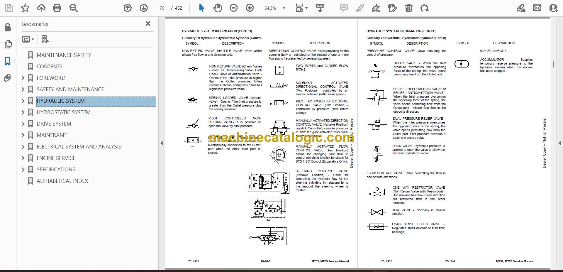
- HYDRAULIC SYSTEM INFORMATION
- Glossary Of Hydraulic / Hydrostatic Symbols
- Troubleshooting
- CYLINDER (LIFT)
- Testing
- Removal And Installation
- Parts Identification
- Disassembly And Assembly
- CYLINDER (TILT)
- Testing
- Removal And Installation
- Rod End Pivot Pin Bushing And Seal Removal And Installation
- Parts Identification
- Disassembly And Assembly
- MAIN RELIEF VALVE
- Description
- Testing
- Removal And Installation
- PORT RELIEF VALVES
- Testing (Lift)
- Removal And Installation (Lift)
- Testing (Tilt)
- Removal And Installation (Tilt)
- HYDRAULIC CONTROL VALVE (S/N A3WR11001 – A3WR17614, A3WT11001 – A3WT17578, A3WU11001 – A3WU13084)
- Description
- Removal And Installation
- Identification Chart
- Disassembly And Assembly
- HYDRAULIC CONTROL VALVE (S/N A3WR17615 & ABOVE, A3WT17579 & ABOVE, A3WU13085 & ABOVE, B38R11001 & ABOVE, B38T11001 & ABOVE, B38U11001 & ABOVE)
- Description
- Removal And Installation
- Identification Chart
- Disassembly And Assembly
- HYDRAULIC PUMP
- Direct Pump Testing
- Removal And Installation
- Parts Identification
- Disassembly And Assembly
- HYDRAULIC / HYDROSTATIC FILTER
- Description
- Housing Removal And Installation
- HYDRAULIC FLUID RESERVOIR
- Description
- Removal And Installation
- OIL COOLER
- Description
- Removal And Installation
- HYDROSTATIC SYSTEM
- HYDROSTATIC SYSTEM INFORMATION
- Troubleshooting
- Description
- HYDROSTATIC MOTOR
- Description
- Removal And Installation
- Parts Identification
- Disassembly
- Inspection
- Assembly
- CHARGE PRESSURE
- Description
- Testing
- Sender Removal And Installation
- Replacing Poppet Assembly
- HYDROSTATIC PUMP
- Description
- Removal And Installation
- Replenishing / High Pressure Relief Valve Removal And Installation
- Parts Identification
- Disassembly
- Assembly
- DRIVE BELT
- Description
- Shield Removal And Installation
- Adjusting
- Alignment
- Belt Removal And Installation
- Tensioner Pulley Removal And Installation
- HYDROSTATIC CONTROLS
- Steering Control Panel Removal And Installation
- Steering Control Panel Disassembly And Assembly
- Steering Shaft Assembly Removal And Installation
- Steering Linkage Adjustment
- Adjusting Reverse Speed Control
- DRIVE SYSTEM
- PARKING BRAKE
- Description
- Handle Removal And Installation
- Cable Removal And Installation
- Cable Adjustment
- Linkage Assembly Removal And Assembly
- Brake Pin Lubrication
- TRACK CARRIAGE COMPONENTS
- Description
- Checking Tension
- Adjusting Tension
- Track Removal And Installation
- Idler (Front) Removal And Installation
- Idler (Front) Disassembly And Assembly
- Idler (Rear) Removal And Installation
- Idler (Rear) Parts Identification
- Idler (Rear) Disassembly And Assembly
- Tensioner Disassembly And Assembly
- Roller Removal And Installation
- Roller Parts Identification
- Roller Disassembly And Assembly
- Carriage Removal And Installation
- Track Damage Identification
- MAINFRAME
- BOB-TACH
- Removal And Installation
- Seal Removal And Installation
- Lever And Wedge Disassembly And Assembly
- COMMON INDUSTRY INTERFACE (CII)
- CII – Removal And Installation
- CII – Seal Removal And Installation
- CII – Lever And Wedge Disassembly And Assembly
- LIFT ARMS
- REAR DOOR
- Removal And Installation
- Rear Door Panel Removal And Installation
- Striker Removal And Installation
- Striker (Adjusting)
- Latch Removal And Installation
- Bumper (Adjusting)
- FUEL TANK
- Removal And Installation
- Fuel Level Sender Removal And Installation
- INSTRUMENT PANEL
- GRAB BAR
- HOOD
- Removal And Installation
- Disassembly And Assembly
- Latch Removal And Installation
- Striker (Adjusting)
- REVERSE STOP PANEL
- Description
- Inspecting Function
- Removal And Installation
- Reverse Stop Mechanism Removal And Installation
- Reverse Stop Mechanism Disassembly And Assembly
- BOTTOM ACCESS PANEL
- RIDE-ON PLATFORM (HINGED)
- Removal And Installation
- Tire Removal And Installation
- Caster With Bushing Removal And Installation
- Caster With Bearings Removal And Installation
- Caster With Bearings Disassembly And Assembly
- ELECTRICAL SYSTEM AND ANALYSIS
- ELECTRICAL SCHEMATICS
- ELECTRICAL SYSTEM INFORMATION
- Glossary Of Electrical Symbols
- Description
- Fuse And Relay Location / Identification (Earlier Models)
- Fuse And Relay Location / Identification (Later Models)
- Troubleshooting
- Solenoid Testing
- BATTERY
- Battery Maintenance
- Maintaining Battery Charge Level
- Battery Service During Machine Storage
- Battery Testing
- Battery Charging
- Removal And Installation
- Using A Booster Battery (Jump Starting)
- ALTERNATOR
- Belt Adjustment
- Belt Replacement
- Description
- Alternator Output Test
- Full Field Test
- Alternator Voltage Testing
- Removal And Installation
- Parts Identification
- STARTER
- Testing
- Removal And Installation
- Parts Identification
- INSTRUMENT PANEL
- Component Removal And Installation
- LIGHTS
- NEUTRAL START SENSOR
- Description
- Removal And Installation
- Sensor Activation Adjustment
- Sensor Activation Bolt Removal
- CONTINUOUS FLOW SHUTOFF SWITCH
- Removal And Installation
- Testing
- ELECTRICAL / HYDRAULIC CONTROLS
- ELECTRIC COOLING FAN
- Description
- Removal And Installation
- ENGINE SERVICE
- ENGINE INFORMATION
- Description
- Specifications (Kubota D722-EB)
- Specifications (Kubota D902-EB)
- Torque Values
- Troubleshooting
- Engine Removal And Installation
- Engine Mount Replacement
- Compression – Checking
- ENGINE SPEED CONTROL
- Removal And Installation
- Disassembly And Assembly
- Cable Removal And Installation
- MUFFLER
- AIR CLEANER
- Housing Removal And Installation
- ENGINE COOLING SYSTEM
- Radiator Removal And Installation
- Fan Blade Removal And Installation
- Water Pump Removal And Installation
- Water Pump Disassembly And Assembly
- Thermostat Housing Removal And Installation
- LUBRICATION SYSTEM
- Oil Pan Removal And Installation
- Oil Pump Removal And Installation
- Oil Pump Inspection
- Engine Oil Pressure – Testing
- FUEL SYSTEM
- Fuel Camshaft Removal And Installation
- Fuel Camshaft Governor Disassembly And Assembly
- Fuel Shutoff Solenoid – Checking
- Fuel Shutoff Solenoid – Installation
- Fuel Injection Pump Removal And Installation
- Fuel Injection Pump – Timing
- Fuel Injector Removal And Installation
- Fuel Injector Nozzle Pressure – Checking
- Nozzle Spray Condition
- Valve Seat Tightness
- CYLINDER HEAD
- Glow Plugs – Testing
- Glow Plugs Removal And Installation
- Valve Clearance Adjustment
- Valve Timing – Checking
- Cylinder Head Removal And Installation
- Cylinder Head Disassembly And Assembly
- Cylinder Head – Servicing
- Cylinder Head Top Clearance
- Valve Guide – Checking
- Reconditioning The Valve And Valve Seat
- Valve Spring
- Valve Tappets
- Rocker Arm And Shaft – Checking
- CRANKSHAFT AND PISTONS
- Piston And Connecting Rod Removal And Installation
- Piston And Connecting Rod – Servicing
- Cylinder Bore – Checking
- Connecting Rod Alignment
- Crankshaft Gear Removal And Installation
- Crankshaft And Bearings Removal And Installation
- Crankshaft And Bearings – Servicing
- CAMSHAFT AND TIMING GEARS
- Timing Gearcase Cover Removal And Installation
- Timing Gears Backlash – Checking
- Idler Gear And Shaft Removal And Installation
- Camshaft – Servicing
- Idler Gear And Shaft Servicing
- HYDRAULIC GEAR PUMP MOUNTING BRACKET
- Removal And Installation
- Hydraulic Gear Pump Coupler Removal And Installation
- FLYWHEEL AND ENGINE MOUNTING BRACKET
- Flywheel Removal And Installation
- Ring Gear Removal And Installation
- Engine Mounting Bracket Removal And Installation
- SPECIFICATIONS
- (MT52) MINI LOADER SPECIFICATIONS
- Machine Dimensions
- Performance
- Controls
- Engine
- Hydraulic System
- Electrical
- Drive System
- Capacities
- Tracks
- Ground Pressure
- (MT55) MINI LOADER SPECIFICATIONS
- Machine Dimensions
- Performance
- Controls
- Engine
- Hydraulic System
- Electrical
- Drive System
- Capacities
- Tracks
- Ground Pressure
- (MT52) TECHNICAL SERVICE GUIDE SPECIFICATIONS – (S/N A3WR11001 & ABOVE, S/N A3WS11001 & ABOVE, S/N B38R11001 & ABOVE)
- Engine
- Engine Torques
- Cooling System
- Electrical
- Loader Torques
- Hydraulic System
- Fuel Consumption
- (MT55) TECHNICAL SERVICE GUIDE SPECIFICATIONS – (S/N A3WT11001 & ABOVE, S/N A3WU11001 & ABOVE, S/N B38T11001 & ABOVE, S/N B38U11001 & ABOVE)
- Engine
- Engine Torques
- Cooling System
- Electrical
- Loader Torques
- Hydraulic System
- Fuel Consumption
- TORQUE SPECIFICATIONS FOR BOLTS
- Torque For General SAE Bolts
- Torque For General Metric Bolts
- HYDRAULIC CONNECTION SPECIFICATIONS
- O-ring Face Seal Connection
- Straight Thread O-ring Fitting
- Tubelines And Hoses
- Flare Fitting
- Port Seal Fitting
- HYDRAULIC FLUID SPECIFICATIONS
- CONVERSIONS
- Decimal And Millimeter Equivalent Chart
- U.S. To Metric Conversion Chart
- SERVICE TOOLS REQUIRED
- Hydraulic Tools
- Engine Tools
- ALPHABETICAL INDEX
Bobcat Software
Bobcat PDF Manuals


