A CT440 is a compact tractor that spends its life on mowers, loaders, augers, and 3-point implements, same idea as a small Deere or New Holland utility rig. The people who grab this manual are the ones actually wrenching on it: small contractors, farmers, and shop mechanics. They want hard info for real repairs, not sales fluff. Think engine work, hydraulic leaks, electrical gremlins, and hydrostatic drive issues.
What this manual helps you do
- Diagnose hydraulic problems in the loader, 3-point, and steering circuits, then pressure-test and verify repairs
- Trace, test, and repair wiring and electrical faults using proper diagrams and step-by-step checks
- Follow teardown and reassembly procedures on the engine, front axle, transmission, and hydrostatic drive
- Check, set, and adjust linkages, clutches, brakes, and 3-point hitch components after repair
- Replace and correctly set seals, bearings, and gaskets in pumps, valves, cylinders, and driveline parts
Who this is for
This is for anyone responsible for fixing a Bobcat CT440 in the ABHE11001-ABHE99999 serial range: owner-operators, farm shops, independent mechanics, or rental fleets. If you only need how to start it, run it, and basic maintenance intervals, you want the operator's handbook instead, not this manual.
FAQ
Q: Is this a searchable PDF, and can I read the wiring diagrams clearly?
A: These manuals are normally supplied as searchable PDFs and the wiring diagrams are laid out so you can zoom in and read connector labels.
Q: How do I know if it fits my exact tractor?
A: If your CT440 serial number falls between ABHE11001 and ABHE99999, this is the correct service manual family for your machine.
Q: Is this the right document for fault codes and real repairs?
A: Yes, this is the workshop service manual, the one you use for diagnostics, specs, and repair procedures, not just basic operation.
Bottom line: If you're actually repairing a CT440 in that serial range, this is the right manual. If you're just learning to run it, it's the wrong book.
📘 Show Index
Table of Contents:
- MAINTENANCE SAFETY
- CONTENTS
- FOREWORD
- FOREWORD
- SAFETY INSTRUCTIONS
- Use Safety Rules
- Safety Rules For Power Take-Off (PTO) Driven Implements
- Compact Tractor Requirements and Capabilities
- FIRE PREVENTION
- Maintenance
- Operation
- Electrical
- Hydraulic System
- Fueling
- Starting
- Spark Arrester Exhaust System
- Welding And Grinding
- Fire Extinguishers
- SERIAL NUMBER LOCATIONS
- Compact Tractor Serial Number
- Engine Serial Number
- Loader Serial Number (Optional)
- DELIVERY REPORT
- COMPACT TRACTOR IDENTIFICATION
- COMPACT TRACTOR IDENTIFICATION (WITH OPTIONAL LOADER AND REAR BALLAST)
- COMPACT TRACTOR IDENTIFICATION (WITH OPTIONAL THREE-POINT IMPLEMENT AND FRONT BALLAST)
- COMPACT TRACTOR IDENTIFICATION (WITH OPTIONAL CAB)
- SAFETY & MAINTENANCE
- SUPPORTING THE COMPACT TRACTOR ON JACKSTANDS
- ENGINE COVER
- SEAT BELT
- Inspection And Maintenance
- TRANSPORTING THE COMPACT TRACTOR ON A TRAILER
- Loading And Unloading
- Fastening
- TOWING THE COMPACT TRACTOR
- AXLE TOE IN (HST MODELS)
- Inspection And Maintenance
- AXLE TOE IN (SST MODELS)
- SERVICE SCHEDULE
- AIR CLEANER SERVICE
- FRESH AIR FILTERS (WITH CAB)
- ENGINE COOLING SYSTEM
- Checking Level
- Cleaning
- Hoses And Clamps
- Removing And Replacing Coolant
- FUEL SYSTEM
- Fuel Specifications
- Biodiesel Blend Fuel
- Filling The Fuel Tank
- Fuel Filter
- Removing Air From The Fuel System
- Filling A Portable Fuel Container
- ENGINE LUBRICATION SYSTEM
- Checking And Adding Engine Oil
- Engine Oil Chart
- Removing And Replacing Oil And Filter
- HYDRAULIC / HYDROSTATIC / TRANSMISSION SYSTEM
- Checking And Adding Fluid
- Transmission / Differential Fluid Chart
- Removing And Replacing Hydraulic / Hydrostatic / Transmission Filters
- Removing And Replacing Hydraulic / Transmission Fluid
- Hoses And Clamps
- FRONT AXLE
- Checking And Adding Lubricant
- Removing And Replacing Lubricant
- Axle Pivot
- SPARK ARRESTER MUFFLER
- COMPACT TRACTOR STORAGE AND RETURN TO SERVICE
- Storage
- Return To Service
- ALTERNATOR BELT
- Belt Adjustment
- Belt Replacement
- AIR CONDITIONING BELT
- Belt Adjustment
- Belt Replacement
- LUBRICATING THE COMPACT TRACTOR
- TIRE MAINTENANCE
- Front Wheel Nuts / Bolts
- Rear Wheel Nuts / Bolts
- Mounting
- Wheel Spacing (AG And Industrial Tires Only)
- PIVOT PINS
- Inspection And Maintenance
- SAFETY INTERLOCK SYSTEM – NEUTRAL START
- Inspection And Maintenance (HST)
- Inspection And Maintenance (SST)
- SAFETY INTERLOCK SYSTEM – OPERATING
- Inspection And Maintenance (HST)
- Inspection And Maintenance (SST)
- PARKING BRAKE SYSTEM
- Inspection And Maintenance
- BRAKE SYSTEM
- Inspection And Maintenance
- Adjusting
- TRAVEL CONTROL PEDAL (HST ONLY)
- Inspection And Maintenance
- F-N-R LEVER (SST ONLY)
- Inspection And Maintenance
- CRUISE CONTROl (HST ONLY)
- Inspection And Maintenance
- CLUTCH PEDAL (SST ONLY)
- Inspection And Maintenance
- SPEED RANGE LEVER (HST ONLY)
- BOB-TACH (HAND LEVER)
- Inspection And Maintenance
- CLUTCH PEDAL AND HOUSING (SST ONLY)
- Draining Water
- Storage Position
- DIFFERENTIAL LOCK
- Inspection And Maintenance
- Adjustment
- HYDRAULIC SYSTEM
- HYDRAULIC/HYDROSTATIC
SCHEMATICS
- HYDRAULIC SYSTEM INFORMATION
- Glossary Of Hydraulic / Hydrostatic Symbols For Compact Tractors
- Troubleshooting The Hydraulic Circuit
- Troubleshooting The Joystick Valve Circuit
- Troubleshooting The Power Lift Circuit
- Troubleshooting The Steering Circuit
- MAIN RELIEF VALVE
- Testing Information
- Testing And Adjusting The Main Relief Valve
- HYDRAULIC PUMP
- Removal And Installation
- Parts Identification
- Disassembly
- Assembly
- STEERING VALVE
- Removal And Installation
- Parts Identification
- Disassembly
- Inspection
- Assembly
- STEERING VALVE TESTING
- Relief Pressure
- Working Pressure
- STEERING CYLINDER
- Removal And Installation
- Parts Identification
- Disassembly And Assembly
- STEERING CYLINDER (SST MODELS)
- Removal And Installation
- Parts Identification
- Disassembly
- Assembly
- RIGHT JOYSTICK (WITHOUT CAB)
- Removal And Installation
- Parts Identification
- Disassembly And Assembly
- Adjustment
- RIGHT JOYSTICK (WITH CAB)
- Removal And Installation
- Parts Identification
- Disassembly And Assembly
- Adjustment
- RIGHT JOYSTICK VALVE (IF EQUIPPED)
- Removal And Installation
- Parts Identification
- Disassembly
- Inspection
- Assembly
- REAR PTO
- Engagement Testing
- Adjustment
- OIL COOLER (HST MODELS)
- THREE POINT HITCH HOUSING
- AUXILIARY CONTROL VALVE
- End Cap Section Disassembly And Assembly
- Valve Section Parts Identification
- Valve Section Disassembly And Assembly
- Detent Assembly
- ROCK SHAFT
- MLS VALVE
- Removal And Installation
- Parts Identification
- Disassembly And Assembly
- Adjustment (HST Models)
- Adjustment (SST Models)
- THREE POINT CYLINDER
- Disassembly And Assembly
- Inspection
- THREE POINT CYLINDER CONTROL
- Disassembly And Assembly
- Adjusting The Position Control Lever (HST Models)
- Adjusting The Position Control Lever (SST Models)
- MODULATOR VALVE
- Removal And Installation
- Parts Identification
- Disassembly And Assembly
- FRONT WHEEL DRIVE
- Engagement Testing
- Adjustment
- CYLINDER (Lift) (EARLY MODELS)
- Testing
- Removal And Installation
- Parts Identification
- Disassembly
- Assembly
- CYLINDER (LIFT) (LATE MODELS)
- Testing
- Removal And Installation
- Parts Identification
- Disassembly
- Assembly
- CYLINDER (TILT) (EARLY MODELS)
- Testing
- Removal And Installation
- Parts Identification
- Disassembly
- Assembly
- CYLINDER (TILT) (LATE MODELS)
- Testing
- Removal And Installation
- Parts Identification
- Disassembly
- Assembly
- HYDROSTATIC SYSTEM
- HYDROSTATIC SYSTEM INFORMATION (HST MODELS)
- HYDROSTATIC PUMP (HST MODELS)
- Removal And Installation
- Parts Identification
- Disassembly
- Inspection
- Assembly
- Hydrostatic Pump Start-Up
- HYDROSTATIC PUMP TESTING (HST MODELS)
- Charge Pressure Testing
- Hydrostatic Drive Pressure Testing
- Neutral Valves
- TRAVEL CONTROL PEDALS (HST MODELS)
- TRAVEL CONTROL PEDAL LINKAGE (HST MODELS)
- TRAVEL CONTROL PEDAL PIVOT ARMS (HST MODELS)
- DRIVE SYSTEM
- SERVICE BRAKE
- Troubleshooting Chart
- Description
- Inspection And Maintenance
- Adjusting
- Stop Switch Adjustment (HST Models)
- Stop Switch Adjustment (SST Models)
- BRAKE PEDAL ASSEMBLY
- BRAKE / CLUTCH PEDAL ASSEMBLY (SST MODELS)
- DRIVESHAFT (EARLY MODELS)
- DRIVESHAFT (LATER MODELS)
- AXLE CASE
- Removal And Installation
- Parts Identification
- Disassembly And Assembly
- BRAKE CASE
- Removal And Installation
- Parts Identification
- Disassembly And Assembly
- Inspection
- TRANSMISSION (HST MODELS)
- Troubleshooting Chart
- Middle Case / PTO Clutch Group Parts Identification
- Middle Case / PTO Clutch Group Disassembly
- Middle Case / PTO Clutch Group Inspection
- Middle Case / PTO Countershaft Group Parts Identification
- Middle Case / PTO Countershaft Group Disassembly
- Middle Case / PTO Countershaft Group Inspection
- Middle Case / 23 Gear Shaft Group Parts Identification
- Middle Case / 23 Gear Shaft Group Disassembly
- Middle Case / 23 Gear Shaft Group Inspection
- Middle Case / Countershaft Group Parts Identification
- Middle Case / Countershaft Group Disassembly
- Middle Case / Countershaft Group Inspection
- Bearing Cover / Shift Links Parts Identification
- Bearing Cover / Shift Links Disassembly
- Bearing Cover / Shift Links Inspection
- Pinion Shaft Group Parts Identification
- Pinion Shaft Group Disassembly
- Pinion Shaft Group Inspection
- PTO Shaft Group Parts Identification
- PTO Shaft Group Disassembly
- PTO Shaft Group Inspection
- Range Shifter Shaft Group Parts Identification
- Range Shifter Shaft Group Disassembly
- Range Shifter Shaft Group Inspection
- PTO 15 Gear Shaft Group Parts Identification
- PTO 15 Gear Shaft Group Disassembly
- PTO 15 Gear Shaft Group Inspection
- Idle Shaft Group Parts Identification
- Idle Shaft Group Disassembly
- Idle Shaft Group Inspection
- Front Wheel Drive Shaft Group Parts Identification
- Front Wheel Drive Shaft Group Disassembly
- Front Wheel Drive Shaft Group Inspection
- Rear PTO Shaft Group Parts Identification
- Rear PTO Shaft Group Disassembly
- Rear PTO Shaft Group Inspection
- Differential Parts Identification
- Differential Disassembly
- Differential Inspection
- Differential Assembly
- Rear PTO Shaft Group Assembly
- Front Wheel Drive Shaft Group Assembly
- Idle Shaft Group Assembly
- PTO 15 Gear Shaft Group Assembly
- Range Shifter Shaft Group Assembly
- PTO Shaft Group Assembly
- Pinion Shaft Group Assembly
- Bearing Cover / Shift Links Assembly
- Middle Case / Countershaft Group Assembly
- Middle Case / 23 Gear Shaft Group Assembly
- Middle Case / PTO Countershaft Group Assembly
- Middle Case / PTO Clutch Group Assembly
- TRANSMISSION (SST MODELS)
- Troubleshooting Chart
- Transmission Case Removal
- Transmission Case Parts Identification
- Transmission Case Disassembly
- Bearing Cover / PTO Countershaft Parts Identification
- Bearing Cover / PTO Countershaft Disassembly
- Middle Case / 23 Gear Shaft Group Inspection
- Bearing Cover / PTO Countershaft Inspection
- Bearing Cover / PTO Driveshaft Parts Identification
- Bearing Cover / PTO Driveshaft Disassembly
- Bearing Cover / PTO Driveshaft Inspection
- Bearing Cover / Shift Links Parts Identification
- Bearing Cover / Shift Links Disassembly
- Bearing Cover / Shift Links Inspection
- Bearing Cover / Countershaft Parts Identification
- Bearing Cover / Countershaft Disassembly
- Bearing Cover / Countershaft Inspection
- Bearing Cover / Main Shaft Parts Identification
- Bearing Cover / Main Shaft Disassembly
- Bearing Cover / Main Shaft Inspection
- Middle Case Removal
- Middle Case / Bearing Cover Removal
- Middle Case / Shift Link Parts Identification
- Middle Case / Shift Link Disassembly
- Middle Case / Shift Link Inspection
- Middle Case / 19 Gear Shaft Parts Identification
- Middle Case / 19 Gear Shift Disassembly
- Middle Case / 19 Gear Shaft Inspection
- Middle Case / Shuttle Shaft Parts Identification
- Middle Case / Shuttle Shaft Disassembly
- Middle Case / Shuttle Shaft Inspection
- Middle Case / 23-20 Gear Shaft Parts Identification
- Middle Case / 23-20 Gear Shaft Disassembly
- Middle Case / 23-30 Gear Shaft Inspection
- Middle Case / PTO Clutch Parts Identification
- Middle Case / PTO Clutch Disassembly
- Middle Case / PTO Clutch Inspection
- Middle Case Bearing Cover / Shift Links Parts Identification
- Middle Case Bearing Cover / Shift Links Disassembly
- Middle Case Bearing Cover / Shift Links Inspection
- Pinion Shaft Parts Identification
- Pinion Shaft Disassembly
- Pinion Shaft Inspection
- PTO Shaft Parts Identification
- PTO Shaft Disassembly
- PTO Shaft Inspection
- Range Shifter Shaft Parts Identification
- Range Shifter Shaft Disassembly
- Range Shifter Shaft Inspection
- PTO 15 Gear Shaft Parts Identification
- PTO 15 Gear Shaft Disassembly
- PTO 15 Gear Shaft Inspection
- Idle Shaft Parts Identification
- Idle Shaft Disassembly
- Idle Shaft Inspection
- Front Wheel Drive Shaft Parts Identification
- Front Wheel Drive Shaft Disassembly
- Front Wheel Drive Shaft Inspection
- Rear PTO Shaft Parts Identification
- Rear PTO Shaft Disassembly
- Rear PTO Shaft Inspection
- Differential Parts Identification
- Differential Disassembly
- Differential Inspection
- Differential Assembly
- Rear PTO Shaft Assembly
- Front Wheel Drive Shaft Assembly
- Idle Shaft Assembly
- PTO 15 Gear Shaft Assembly
- Range Shifter Shaft Assembly
- PTO Shaft Assembly
- Pinion Shaft Assembly
- Middle Case Bearing Cover / Shift Links Assembly
- Middle Case / PTO Clutch Assembly
- Middle Case / 23-20 Gear Shaft Assembly
- Middle Case / Shuttle Shaft Assembly
- Middle Case / 19 Gear Shaft Assembly
- Middle Case / Shift Link Assembly
- Middle Case / Bearing Cover Installation
- Middle Case Installation
- Bearing Cover / Main Shaft Assembly
- Bearing Cover / Countershaft Assembly
- Bearing Cover / Shift Links Assembly
- Bearing Cover / PTO Driveshaft Assembly
- Bearing Cover / PTO Countershaft Assembly
- Transmission Case Assembly
- Transmission Case Installation
- FRONT AXLE
- FRONT AXLE (SST MODELS)
- AXLE AND DIFFERENTIAL
- Troubleshooting Chart
- Front Axle Cover Parts Identification
- Front Axle Cover Disassembly
- Front Axle Cover Inspection
- Front Axle Case Group Parts Identification
- Front Axle Case Group Disassembly
- Bevel Gear Case Group Parts Identification
- Bevel Gear Case Group Disassembly
- Bevel Gear Case Group Inspection
- Axle Shaft Group Parts Identification
- Axle Shaft Group Disassembly
- Axle Shaft Group Inspection
- Axle Support Removal
- Pinion Shaft Removal
- Pinion Shaft Parts Identification
- Pinion Shaft Disassembly
- Pinion Shaft Inspection
- Differential Removal
- Differential Parts Identification
- Differential Disassembly
- Differential Inspection
- Differential Assembly
- Differential Installation
- Pinion Shaft Assembly
- Pinion Shaft Installation
- Axle Support Installation
- Axle Shaft Group Assembly
- Bevel Gear Case Group Assembly
- Front Axle Case Group Assembly
- Front Axle Cover Assembly
- AXLE AND DIFFERENTIAL (SST MODELS)
- Troubleshooting Chart
- Front Axle Cover Parts Identification
- Front Axle Cover Disassembly
- Front Axle Cover Inspection
- Front Axle Case Group Parts Identification
- Front Axle Case Group Disassembly
- Bevel Gear Case Group Parts Identification
- Bevel Gear Case Group Disassembly
- Bevel Gear Case Group Inspection
- Axle Shaft Group Parts Identification
- Axle Shaft Group Disassembly
- Axle Shaft Group Inspection
- Axle Support Removal
- Pinion Shaft Removal
- Pinion Shaft Parts Identification
- Pinion Shaft Disassembly
- Pinion Shaft Inspection
- Differential Removal
- Differential Parts Identification
- Differential Disassembly
- Differential Inspection
- Differential Assembly
- Differential Installation
- Pinion Shaft Assembly
- Pinion Shaft Installation
- Axle Support Installation
- Axle Shaft Group Assembly
- Bevel Gear Case Group Assembly
- Front Axle Case Group Assembly
- Front Axle Cover Assembly
- STEERING AXLE ADJUSTMENT (HST MODELS)
- Toe-In Checking
- Toe-In Adjustment
- Rocking Force
- Steering Angle Adjustment
- STEERING AXLE ADJUSTMENT (SST MODELS)
- Rocking Force
- Steering Angle Adjustment
- Toe-In Checking
- Toe-In Adjustment
- SEPARATING THE TRACTOR (HST MODELS)
- SEPARATING THE TRACTOR (SST MODELS)
- MAINFRAME
- OPERATOR SEAT
- CONSOLE COVER (WITHOUT CAB)
- Left Side Removal And Installation
- Right Side Removal And Installation
- CONSOLE COVER (WITH CAB)
- Left Side Removal And Installation
- Right Side Removal And Installation
- TRANSMISSION CASE (HST MODELS)
- TRANSMISSION CASE (SST MODELS)
- FUEL TANK
- MID PTO CONTROL
- Lever Removal And Installation
- SPLASH BOARD
- FLOOR MAT (HST MODELS)
- FLOOR MAT (SST MODELS)
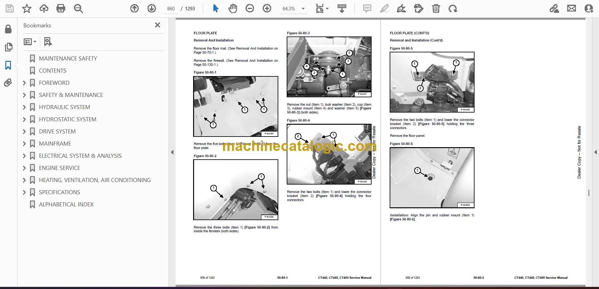
- FLOOR PLATE
- ENGINE COVER
- Gas Cylinder Removal And Installation
- Removal And Installation
- GRILLE
- ENGINE SIDE COVER
- FENDER ASSEMBLY (WITHOUT CAB) (HST MODELS)
- Removal And Installation
- Fender Mount Removal And Installation
- FENDER ASSEMBLY (SST MODELS)
- Removal And Installation
- Fender Mount Removal And Installation
- FENDER (WITHOUT CAB)
- FENDER (WITH CAB)
- FIREWALL (WITHOUT CAB) (HST MODELS)
- FIREWALL (SST MODELS)
- FIREWALL (WITH CAB) (HST MODELS)
- ROPS
- Removal And Installation
- Bracket Removal And Installation
- PTO SAFETY SHIELD
- DRAW BAR
- DRAW BAR ASSEMBLY
- THREE POINT HITCH LOWER LINKS
- Left Side Removal And Installation
- Right Side Removal And Installation
- Top Link Assembly Removal And Installation
- FRONT WORK LIGHT MOUNT (WITH CAB)
- CAB COVER
- CAB POST COVER
- INNER FENDER ACCESS COVER (WITH CAB)
- CAB (HST MODELS)
- Removal And Installation
- Door Removal And Installation
- Windshield Removal And Installation
- Front Lower Window Removal And Installation
- Lower Front Window Removal And Installation
- Rear Window Removal And Installation
- Side Window Removal And Installation
- Door Glass Removal And Installation
- HEADLINER
- BOB-TACH (HAND LEVER)
- Description
- Removal And Installation
- Parts Identification
- Lever And Wedge Disassembly And Assembly
- ELECTRICAL SYSTEM & ANALYSIS
- ELECTRICAL SCHEMATICS
- ELECTRICAL SYSTEM INFORMATION
- Glossary Of Electrical Symbols
- Electrical Component Location (Without Cab) (HST Models)
- Electrical Component Location (With Cab) (HST Models)
- Electrical Component Location (SST Models)
- Troubleshooting
- ELECTRICAL SYSTEM
- Description
- Fuse And Relay Location – Engine Compartment
- Fuse And Relay Location – Cab (If Equipped)
- Fuse And Relay Location – Instrument Panel – HST Models
- Fuse And Relay Location – Instrument Panel – SST Models
- BATTERY
- Removing And Installing Battery
- Battery Maintenance
- Using A Booster Battery (Jump Starting)
- ALTERNATOR
- Belt Adjustment
- Belt Replacement
- Charging System Inspection
- Alternator Voltage Testing
- Low Voltage Testing
- High Voltage Testing
- Removal And Installation
- Parts Identification
- STARTER
- Testing
- Removal And Installation
- Parts Identification
- HOOD LIGHTS
- Removal And Installation
- Bulb Removal And Installation
- REAR LIGHTS
- Removal And Installation
- Bulb Removal And Installation
- FRONT LIGHTS (WITH CAB)
- Removal And Installation
- Bulb Removal And Installation
- SEAT SENSOR
- FUEL LEVEL SENDER
- INSTRUMENT PANEL
- STEERING COLUMN COVER
- PTO SWITCH (REAR)
- Inspection And Maintenance
- Removal And Installation
- PTO LEVER (MID) (IF EQUIPPED)
- Inspection And Maintenance
- PTO Switch Removal And Installation
- Adjustment
- HORN
- REAR WORK LIGHT (WITH CAB)
- Removal And Installation
- Disassembly And Assembly
- FRONT WORK LIGHT (WITH CAB)
- Removal And Installation
- Disassembly And Assembly
- CRUISE CONTROL (HST ONLY)
- Inspection And Maintenance
- Switch Removal And Installation
- Magnet Removal And Installation
- Controller Removal And Installation
- SPEED RANGE LEVER (HST ONLY)
- Calibration
- Controller Removal And Installation
- FORWARD – NEUTRAL – REVERSE (F-N-R) LEVER (SST MODELS)
- Removal And Installation
- F-N-R Lever Disassembly And Assembly
- ENGINE SERVICE
- ENGINE INFORMATION (CT440, ENGINE MODEL 4A200LWH)
- Description
- Specifications
- Troubleshooting
- Engine Removal And Installation (All Models)
- Compression – Checking
- ENGINE INFORMATION (CT445, ENGINE MODEL 4A220LWH)
- Description
- Specifications
- Troubleshooting
- Engine Removal And Installation (All Models)
- Compression – Checking
- ENGINE INFORMATION (CT450, ENGINE MODEL 4B243LWH)
- Description
- Specifications
- Engine Bolt Torque
- Troubleshooting
- Engine Removal And Installation (All Models)
- Compression – Checking
- ENGINE SPEED CONTROL
- Cable Removal And Installation
- Lever Removal And Installation
- ENGINE SPEED CONTROL PEDAL (SST MODELS)
- Removal And Installation
- Cable Removal And Installation
- SPARK ARRESTER MUFFLER
- AIR CLEANER
- ENGINE COOLING SYSTEM
- Description
- Radiator Removal And Installation
- Water Pump Removal And Installation
- Water Pump Disassembly And Assembly
- Thermostat Housing Removal And Installation
- Testing The Thermostat
- LUBRICATION SYSTEM
- Description
- Oil Pan Removal And Installation
- Oil Pump Removal And Installation
- Oil Pump Inspection
- Engine Oil Pressure – Testing
- Oil Filter
- FUEL SYSTEM
- Description
- Fuel Camshaft Removal And Installation
- Fuel Shutoff Solenoid Checking
- Fuel Shutoff Solenoid Removal And Installation
- Fuel Injection Pump Removal And Installation
- Fuel Injection Pump Timing
- Fuel Injector Removal And Installation
- Fuel Injector Nozzle Pressure – Checking
- Nozzle Spray Condition
- Valve Seat Tightness
- Bleeding The Fuel System
- CYLINDER HEAD
- Glow Plug – Testing
- Glow Plug Removal And Installation
- Valve Clearance Adjustment
- Valve Timing – Checking
- Cylinder Head Removal And Installation
- Cylinder Head Bolt Tightening Procedure
- Cylinder Head Disassembly And Assembly
- Cylinder Head Servicing
- Cylinder Head Top Clearance
- Valve Guide – Checking
- Reconditioning The Valve And Valve Seat
- Valve Spring
- Valve Tappets
- Rocker Arm And Shaft – Checking
- CRANKSHAFT AND PISTONS
- Piston And Connecting Rod Removal And Installation
- Piston And Connecting Rod – Servicing
- Cylinder Bore – Checking
- Connecting Rod – Alignment
- Crankshaft And Bearings Removal And Installation
- Crankshaft And Bearings – Servicing
- CAMSHAFT AND TIMING GEARS
- Timing Gearcase Cover Removal And Installation
- Timing Gears Backlash – Checking
- Idler Gear And Shaft Removal And Installation
- Camshaft – Servicing
- Idler Gear And Shaft – Servicing
- FLYWHEEL AND HOUSING (HST MODELS)
- Flywheel Removal And Installation
- Flywheel Housing Removal And Installation
- FLYWHEEL AND HOUSING (SST MODELS)
- Flywheel Removal And Installation
- Flywheel Housing Removal And Installation
- FAN
- CLUTCH ASSEMBLY (SST MODELS)
- Troubleshooting Chart
- Removal And Installation
- Clutch Disc Inspection
- Pressure Plate Inspection
- Clutch Pedal Play And Stopper Bolt Adjustment
- CLUTCH LEVER (SST MODELS)
- Parts Identification
- Disassembly
- Inspection
- Assembly
- HEATING, VENTILATION, AIR CONDITIONING
- HEATER COIL
- BLOWER FAN
- HEATER VALVE
- AIR CONDITIONING SYSTEM FLOW
- COMPONENTS
- SAFETY
- REGULAR MAINTENANCE
- Fresh Air Filter
- Air Conditioning Belt
- Cleaning The Condenser
- RESISTOR
- GENERAL AIR CONDITIONING SERVICE GUIDELINES
- Compressor Oil
- Compressor Oil Check
- Component Replacement And Refrigeration Leaks
- SYSTEM TROUBLESHOOTING CHART
- Blower Motor Does Not Operate
- Gauge Pressure Related Troubleshooting
- TEMPERATURE / PRESSURE
- AIR CONDITIONING SERVICE
- SYSTEM CHARGING AND RECLAMATION
- Reclamation Procedure
- Charging Procedure With A Manifold Gauge Set
- COMPRESSOR
- CONDENSER
- RECEIVER / DRIER
- HVAC CONTROL PANEL
- PRESSURE SWITCH
- EVAPORATOR / HEATER UNIT
- EVAPORATOR / HEATER UNIT COVER
- FRONT AIR DUCT
- SIDE AIR DUCT
- THERMOSTAT
- EXPANSION VALVE
- EVAPORATOR
- SPECIFICATIONS
- CT440 SPECIFICATIONS (HST)
- Compact Tractor Loader Lift Capacities
- Ballast (Rear)
- Three-Point Hitch Specifications
- Towing Weight
- Maximum Drawbar Tongue Weight
- Ballast (Front)
- Dimensions (Standard Machine)
- Dimensions (With Optional Loader, S/N AL4F00101 & Above, S/N AKPW00101 & Above)
- Dimensions (With Optional Loader, S/N AE3500101 & Above)
- Performance
- Controls
- Engine
- Hydraulic System
- Electrical
- Power Take-Off (PTO) System (Rear-PTO)
- Power Take-Off (PTO) System (Mid-PTO Optional)
- Drive System
- Steering
- Capacities
- Tires
- Loader (If Equipped)
- CT445 SPECIFICATIONS (HST)
- Compact Tractor Loader Lift Capacities
- Ballast (Rear)
- Three-Point Hitch Specifications
- Towing Weight
- Maximum Drawbar Tongue Weight
- Ballast (Front)
- Dimensions (Standard Machine)
- Dimensions (With Optional Loader, S/N AL4F00101 & Above, S/N AKPW00101 & Above)
- Dimensions (With Optional Loader, S/N AE3500101 & Above)
- Performance
- Controls
- Engine
- Hydraulic System
- Electrical
- Power Take-Off (PTO) System (Rear-PTO)
- Power Take-Off (PTO) System (Mid-PTO Optional)
- Drive System
- Steering
- Capacities
- Tires
- Loader (If Equipped)
- CT445 SPECIFICATIONS (sST)
- Compact Tractor Loader Lift Capacities
- Ballast (Rear)
- Three-Point Hitch Specifications
- Towing Weight
- Maximum Drawbar Tongue Weight
- Ballast (Front)
- Dimensions (Standard Machine)
- Dimensions (With Optional Loader, S/N AL4F00101 & Above, S/N AKPW00101 & Above)
- Dimensions (With Optional Loader, S/N AE3500101 & Above)
- Performance
- Controls
- Engine
- Hydraulic System
- Electrical
- Power Take-Off (PTO) System (Rear-PTO)
- Power Take-Off (PTO) System (Mid-PTO Optional)
- Drive System
- Steering
- Capacities
- Tires
- Loader (If Equipped)
- CT450 SPECIFICATIONS (HST)
- Compact Tractor Loader Lift Capacities
- Ballast (Rear)
- Three-Point Hitch Specifications
- Towing Weight
- Maximum Drawbar Tongue Weight
- Ballast (Front)
- Dimensions (Standard Machine)
- Dimensions (With Optional Loader, S/N AL4F00101 & Above, S/N AKPW00101 & Above)
- Dimensions (With Optional Loader, S/N AE3500101 & Above)
- Performance
- Controls
- Engine
- Hydraulic System
- Electrical
- Power Take-Off (PTO) System (Rear-PTO)
- Power Take-Off (PTO) System (Mid-PTO Optional)
- Drive System
- Steering
- Capacities
- Tires
- Loader (If Equipped)
- CT450 SPECIFICATIONS (sST)
- Compact Tractor Loader Lift Capacities
- Ballast (Rear)
- Three-Point Hitch Specifications
- Towing Weight
- Maximum Drawbar Tongue Weight
- Ballast (Front)
- Dimensions (Standard Machine)
- Dimensions (With Optional Loader, S/N AL4F00101 & Above, S/N AKPW00101 & Above)
- Dimensions (With Optional Loader, S/N AE3500101 & Above)
- Performance
- Controls
- Engine
- Hydraulic System
- Electrical
- Power Take-Off (PTO) System (Rear-PTO)
- Power Take-Off (PTO) System (Mid-PTO Optional)
- Drive System
- Steering
- Capacities
- Tires
- Loader (If Equipped)
- TORQUE SPECIFICATIONS FOR BOLTS
- Torque For General SAE Bolts
- Torque For General Metric Bolts
- HYDRAULIC FLUID SPECIFICATIONS
- CONVERSIONS
- Decimal And Millimeter Equivalent Chart
- U.S. To Metric Conversion Chart
- FUEL, COOLANT AND LUBRICANTS (ALL MODELS)
- ALPHABETICAL INDEX
Bobcat Software
Bobcat PDF Manuals


