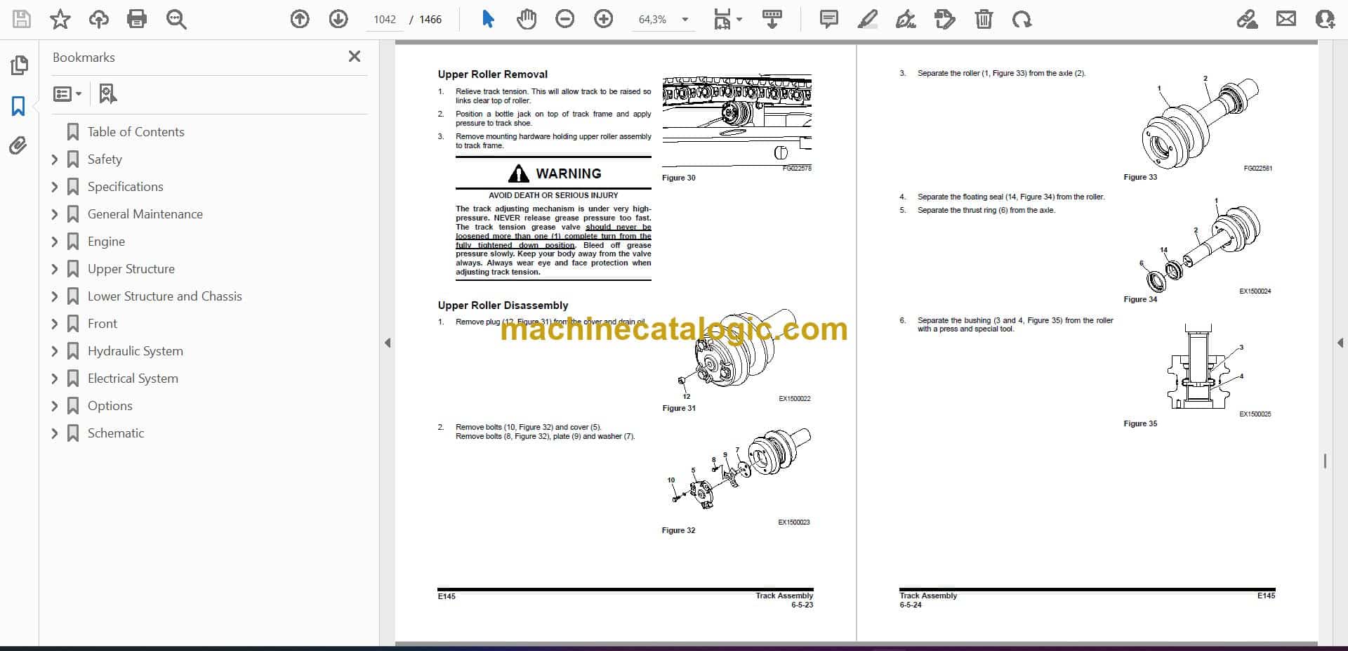
The E145 is a good-sized compact excavator, the kind you put on trenching, site prep, feedlot work, and loading trucks. When something quits swinging, tracks slow down, or you lose boom power, this is the book you grab in the shop on a Friday night so it's running again by Monday. Field techs and owner-operators use this manual to chase hydraulic issues, sort out wiring faults, and get correct specs when parts have to come apart.
What this manual helps you do
- Diagnose hydraulic problems, check pressures, and trace slow or weak functions in the boom, arm, bucket, and travel.
- Follow teardown and reassembly steps for the diesel engine, including timing, sealing surfaces, and reinstalling accessories.
- Troubleshoot the electrical system using wiring diagrams, from dead panels and sensors to intermittent shorts.
- Rebuild or reseal major components like cylinders, swing motor, and travel motors, then verify they're set up correctly.
- Adjust controls, linkages, and travel straightness so the machine digs, swings, and tracks the way it should.
Who this is for
This manual is for anyone working on a Bobcat E145 excavator in the serial range B4WU11001 through B4WU99999, whether you're a small contractor, farm owner, rental fleet, or shop mechanic. If you only want basic operating tips, safety, and daily checks, you want the operator's handbook instead.
FAQ
Q: Is this a searchable PDF and are the wiring diagrams readable?
A: Yes, it's typically a searchable PDF and the wiring diagrams are laid out so you can zoom in and follow circuits.
Q: How do I know if it covers my exact machine?
A: If your E145 serial number falls between B4WU11001 and B4WU99999, this is the right service manual.
Q: Is this the right document if I'm doing my own repairs?
A: Yes, this is the workshop-level service manual, meant for real repair work, not just basic operation.
If your E145's serial tag lands in that B4WU11001-B4WU99999 range and you're turning your own wrenches, this is the manual you want.
📘 Show Index
Table of Contents:
- Table of Contents
- Safety
- Track Excavator Maintenance Safety
- Safety Instructions
- Safety Messages
- General
- Safe Operation is Operator's Responsibility
- Know Your Machine
- Proper Work Tools and Attachments
- Pressurized Fluids
- Flying or Falling Objects
- Personal Protective Equipment (PPE)
- Correction of Machine Problems
- Crushing and Cutting
- Hot Coolant and Oils – Burn Prevention
- Fire and Explosion Prevention
- Fire Extinguisher and First-aid Kit (Emergency Medical Kit)
- Electrical System and Electrical Shock
- Roll-over Protective Structure (ROPS)
- Transportation
- Obey State and Local Over-the-Road Regulations
- Loading and Unloading
- Transporting Machine
- Operation
- Before Engine Starting
- Work Site
- Entering and Exiting
- Cleaning
- Operator Station
- Seat Belt
- Visibility Information
- Boost Starting or Charging Engine Batteries
- Starting Engine
- Swinging or Traveling
- Lifting and Digging
- Operation on Slopes
- Towing
- Attachment
- Engine Stop
- Parking Machine
- Preservation/Storing Machine
- Maintenance
- Cleaning
- Fire and Explosion Prevention
- Burn Prevention
- Lock Inspection Covers
- Working on Machine
- Track Tension Adjustments
- Supports and Blocking for Work Equipment
- High-pressure Lines, Tubes and Hoses
- Battery
- Environment and Circumstances
- Work Site Areas Requiring Extra Caution
- High-voltage Cables
- Underground Operation
- Working in Water
- Working in Contaminated Environment
- Exhaust Ventilation
- Asbestos Information
- Silica Dust Information
- Disposal of Hazardous Materials
- Sound
- Vibration Information
- Specifications
- Specifications
- Safety Instructions
- General Description
- Component Locations
- Overall Dimensions
- Working Range
- General Specifications
- Approximate Weight of Workload Materials
- Performance Tests
- Purpose of Performance Tests
- Kinds of Tests
- Performance Standards
- Precautions for Evaluation of Test Data
- Definition of "Performance Standard"
- Preparation for Performance Tests
- The Machine
- Test Area
- Precautions
- Make Precise Measurement
- Operational Performance Standard Table
- Operational Performance Test
- Hydraulic Cylinder Cycle Time
- Travel Speed
- Track Revolution Speed
- Mistrack Check
- Swing Speed
- Swing Function Drift Check
- Cylinder Creep
- General Maintenance
- General Maintenance Instructions
- Safety Instructions
- Welding Precautions and Instructions
- Hydraulic System – General Precautions
- Maintenance Service and Repair Procedure
- Hydraulic System Cleanliness and Oil Leaks
- Maintenance Precautions for Hydraulic System Service
- Oil Leakage Precautions
- Cleaning and Inspection
- General Instructions
- Bearing Inspection
- Standard Torques
- Safety Instructions
- Torque Values for Standard Metric Fasteners
- Torque Values for Standard U.S. Fasteners
- Type 8 Phosphate Coated Hardware
- Torque Values for Hose Clamps
- ORFS Swivel Nut Recommended Torque
- Torque Values for Split Flanges
- Torque Wrench Extension Tools
- Torque Multiplication
- Other Uses for Torque Wrench Extension Tools
- Tightening Torque Specifications (Metric)
- Engine
- Engine
- Safety Instructions
- Overview
- General Information
- Major Component Location
- Engine Identification
- Engine Lifting
- Maintenance and Storage
- Engine Specification
- General Specification
- Engine Performance Curves
- Basic Engine
- Cylinder Block
- Cylinder Head
- Valve Mechanism Cover
- Crankcase Breather
- Flywheel and Flywheel Housing
- Actuating System
- Pistons, Rings, and Connecting Rods
- Crankshaft
- Gears and Timing Gear Case
- Camshaft
- Rocker Shaft
- Lubricant System
- Overview
- Engine Oil Pump
- Engine Oil Filter
- Engine Oil Pan
- Engine Oil Pressure – Test
- Excessive Bearing Wear – Inspect
- Excessive Engine Oil Consumption – Inspect
- Increased Engine Oil Temperature – Inspect
- Cooling System
- Overview
- Water Pump
- Water Temperature Regulator
- Engine Oil Cooler
- Piston Cooling Jets
- Fuel System
- Overview
- High-pressure Fuel System
- Water Separator & Pre Fuel Filter (Fuel Prefilter)
- Main Fuel Filter
- Fuel Injection Pump
- Fuel Injection Lines
- Fuel Injectors
- Fuel System – Inspect
- Air in Fuel – Test
- Finding Top Center Position for No. 1 Piston
- Fuel Injection Timing – Check
- Fuel Quality – Test
- Fuel System – Prime
- Cleanliness of Fuel System
- Air Inlet and Exhaust System
- Exhaust System
- Clean Emissions Module (Diesel Oxidation Catalyst (DOC) and Selective Catalytic Reduction (SCR) System)
- DEF Dosing Control System
- Electrical System
- Electrical Control System
- Sensor Locations for the Engine
- Sensor Locations for the Clean Emissions Module
- Electronic Control Module (ECM)
- Electric Component – Remove and Install
- Upper Structure
- Cabin
- Safety Instructions
- Cabin Identification
- Roll-over Protective Structure (ROPS)
- Removal
- Installation
- Completing work
- Dimensions of Cabin Glass
- Removal and Installation of Cabin Glass
- Removal of Cabin Glass
- Installation of Cabin Glass
- Installation of Upper Door Glass
- Installation of Upper Front Glass
- Counterweight
- Safety Instructions
- General
- Warning for Counterweight and Front Attachment Removal
- Removal
- Installation
- Hydraulic Oil Tank
- Safety Instructions
- General
- Specification
- Parts List
- Air Breather
- Removal
- Installation
- Completing Work
- Fuel Tank
- Safety Instructions
- General
- Removal
- Installation
- Completing Work
- Main Pump
- Safety Instructions
- Axial Piston Pump
- General Description
- Specifications
- Overview
- Hydraulic Circuit
- Parts List
- Theory of Operation
- Tools
- Tightening Torque
- Removal
- Installation
- Completing Work
- Disassembly
- Reassembly
- Troubleshooting
- Maintenance Instructions
- Regulator
- Parts List
- Functional Explanation
- Adjustment
- Section View
- Pilot Gear Pump
- Specification
- Parts List
- Theory of Operation
- Port and Hydraulic Circuit
- Precaution
- Drive Coupling (Main Pump)
- Safety Instructions
- General
- Section View
- Disassembly
- Reassembly
- Main Control Valve
- Safety Instructions
- General
- Specification
- Overview
- Parts List
- Theory of Operation
- Cautions for Operation
- Precaution
- Removal
- Installation
- Completing Work
- Disassembly
- Cautions on Disassembly
- Sequence of Disassembly
- Cleaning and Inspection
- Reassembly
- Caution on Assembly
- Sequence of Reassembly
- Troubleshooting and Adjustment
- Troubleshooting
- Adjusting Relief Valve
- Swing Device
- Safety Instructions
- General
- Specification
- Overview
- Parts List
- Theory of Operation
- Cautions for Operation
- Removal
- Installation
- Completing work
- Precaution
- Tools for Disassembly and Assembly
- Tightening Torque
- Disassembly
- Swing Device
- Swing Motor
- 1. Wind the wire rope around motor, Lift up the motor with a crane and clean the motor with cleaning oil. After cleaning, dry with compressed air.
- 2. Drain the oil out of the casing (1).
- 3. Point the end of the driveshaft downward and attach it on a disassembly table for easy disassembling. Before disassembling make a match mark on motor casing (1) and valve casing (2).
- 4. Remove relief valve (37) from valve casing (2).
- 5. Remove RO plug (25) and remove spring (24) and plunger (23) from valve casing (2)
- 6. Remove RO plug (39) and remove reactionless valve (39) from valve casing (2).
- 7. Remove hex socket bolts (30, 31) and disassemble valve casing (2) from casing (1). When loosening bolts, the valve casing will be raised by brake springs.
- 8. Remove brake springs (21) (22 ea) from the brake piston (20).
- 9. Disassemble brake piston (20) from casing (1) by using the special tool for removing the brake piston.
- 10. After placing the motor horizontally, remove cylinder block (17) from driveshaft (3).
- 11. Remove piston assembly (9), retainer (8), spherical bushing (11), collar (12), washer (14). When taking out the cylinder block, be careful not to pull out roller (13). Be careful not to damage the sliding parts of the cylinder block (17), thrust …
- 12. Pull out friction plate (18) (3 ea) and separation plate (19) (3 ea) from casing (1).
- 13. Remove O-ring (27, 29) from casing (1).
- Swing Reduction Gear
- Reassembly
- Swing Motor
- 1. Place casing (1) on the work table.
- 2. Insert oil seal (6) at the casing (1) with a tool.
- 3. Insert the driveshaft (3), roller bearing (4) into casing (1).
- 4. Fix the casing (1) flat, and assemble the retaining ring (36) into the driveshaft (3) with a pair of pliers
- 5. Assemble shoe plate (7) to casing (1).
- 6. Insert roller (13) to cylinder block (17).
- 7. Assemble the retainer (8) with the piston assembly (9) to the cylinder block (17).
- 8. Insert cylinder block (17) to driveshaft (3) by aligning with the spline.
- 9. Place casing (1) downward and assemble separation plate (19) and friction plate (18) in sequence.
- 10. Mount O-ring (27, 29) to casing (1).
- 11. Assemble brake piston (20) to casing (1). If the brake piston is difficult to assemble because of the restriction of the O-ring; screw in two M8 bolts on the brake piston and tap them gently with plastic hammer.
- 12. Assemble brake springs (21) (22 ea) into brake piston (20).
- 13. Assemble the O-ring (28) and the spring pin (26) into the casing (2).
- 14. Assemble of ball bearing (5). Insert it to valve casing (2) while tapping it lightly.
- 15. Assemble valve plate (22) to valve casing (2).
- 16. Mount valve casing (2) to casing (1) and tighten hex socket bolts (30, 31) to specification.
- Swing Reduction Gear
- Troubleshooting
- General Instructions
- Examination of Hydraulic Motor
- 1) Lock the swing and supply high-pressure oil to the motor, and normal drain quantity must be approximately 25 LPM or less.
- Troubleshooting
- Maintenance Instructions
- Replacement Standard of Worn Parts
- Standard of Sliding Surface Correction
- Joystick Valve (Work Lever)
- Safety Instructions
- General
- Specifications
- Overview
- Parts List
- Theory of Operation
- Tools and Torques
- Section View
- Removal
- Installation
- Completing work
- Tools and Torques
- Disassembly
- Reassembly
- Dozer Joystick Valve (Option)
- Safety Instructions
- General
- Specifications
- Overview
- Hydraulic Circuit
- Parts List
- Theory of Operation
- Tools
- Removal
- Installation
- Completing work
- Disassembly
- Reassembly
- Travel Control Valve (with Damper)
- Safety Instructions
- General
- Specification
- Overview
- Parts List
- Theory of Operation
- Tools and Torques
- Section View
- Removal
- Installation
- Completing Work
- Disassembly
- 2. Remove set screw (29) from cam (26).
- Reassembly
- Troubleshooting
- Solenoid Valve
- Safety Instructions
- General
- Specification
- Overview
- Parts List
- Theory of Operation
- Disassembly and Reassembly
- Troubleshooting
- EPPR Valve (One or Two-way)
- Safety Instructions
- General
- Specification
- Overview
- Hydraulic Circuit
- Troubleshooting
- Accumulator
- Safety Instructions
- General
- Gear Pump (Rotation)
- Safety Instructions
- General
- Specification
- Overview
- Location
- Parts List
- Single Gear Pump
- One Spool Valve (Rotating)
- Safety Instructions
- General
- Specification
- Overview
- Theory of Operation
- Disassembly and Assembly
- General Cautions
- Replacement of Spool
- Replacement of Main Relief Valve
- Replacement of Overload Relief Valve
- Replacement of Sub-Block
- Lower Structure and Chassis
- Swing Bearing
- Safety Instructions
- General
- General Description
- Parts List
- Maintenance Guidelines
- Disassembly
- Reassembly
- Center Joint
- Safety Instructions
- General
- General Description
- Overview
- Parts List
- Section View
- Removal
- Installation
- Completing Work
- Disassembly
- Reassembly
- Troubleshooting, Testing and Adjustment
- Center Joint (Dozer)
- Safety Instructions
- General
- General Description
- Overview
- Parts List
- Section View
- Removal
- Installation
- Completing Work
- Disassembly
- Reassembly
- Troubleshooting, Testing and Adjustment
- Travel Device
- Safety Instructions
- General
- Specification
- Overview
- Parts List
- Theory of Operation
- Cautions for Operation
- Precaution
- Tools List for Disassembly and Reassembly
- Removal
- Installation
- Completing Work
- Section View
- Disassembly
- General Precautions
- Disassembly Procedure
- Reassembly
- General Precautions
- Reassembly Procedure
- Performance Test
- Summary of Seal Information
- Troubleshooting
- Track Assembly
- Safety Instructions
- General
- Track Tension
- Track Shoes and Links
- Parts List
- Track Removal
- Track Installation
- Wear Limits and Tolerances
- Sprocket
- Wear Limits and Tolerances
- Front Idler
- Overview
- Parts List
- Front Idler Disassembly
- Front Idler Reassembly
- Wear Limits and Tolerances
- Upper Roller
- Overview
- Parts List
- Upper Roller Removal
- Upper Roller Disassembly
- Upper Roller Reassembly
- Wear Limits and Tolerances
- Lower Roller
- Overview
- Parts List
- Lower Roller Removal
- Lower Roller Installation
- Lower Roller Disassembly
- Lower Roller Reassembly
- Wear Limits and Tolerances
- Track Adjuster
- Parts List
- Disassembly
- Assembly
- Dozer System
- Safety Instructions
- General Description
- Hydraulic Circuit
- Front
- Boom and Arm
- Safety Instructions
- Specifications
- Removal
- Installation
- Arm Installation
- Boom Installation
- Completing Work
- Bucket
- Safety Instructions
- Bucket Tooth Inspection and Replacement
- Bucket O-ring Replacement
- Bucket Detaching and Reversal
- Cylinders
- Safety Instructions
- General
- General Description
- Specification
- Parts List
- Theory of Operation
- Seal of Cylinder
- Special Tools and Materials
- Piston Nut
- Piston Jig
- Steel Bushing Jig
- Dust Wiper Jig
- Slipper Seal Jig
- Slipper Seal Straightening Jig
- Rod Bushing (DD-bushing) Pushing-in Jig
- Disassembly
- Reassembly
- Troubleshooting
- Hydraulic System
- Hydraulic System
- Safety Instructions
- Hydraulic System
- Hydraulic Schematic
- Hydraulic Component and Oil Flow
- Hydraulic Components
- Main Oil Circuit
- Pilot Oil Circuit
- Return Oil Circuit
- Safety Cutoff Valve Operation
- Power Up Valve Operation
- Travel High-speed Valve Operation
- Swing Brake Release Operation
- Travel Forward and Backward Operation
- Boom Up Operation
- Boom Down Operation
- Arm Dump Operation
- Arm Crowd Operation
- Bucket Dump Operation
- Bucket Crowd Operation
- Combined Bucket Crowd and Boom Up Operation
- Combined Travel and Boom, Arm, Bucket or Swing Operation
- Hydraulic System Testing and Adjustment
- Safety Instructions
- Procedural Troubleshooting Baseline Recommendations
- Initial Checks and Tests to Establish Operating Condition of the Excavator
- Pilot Pressure
- Power Mode Valve
- Current Signal and Hydraulic Pressure Adjustments
- Pressure Up Valve
- Pump Input Power Control
- Pump Regulator Adjustment
- Flow Meter and Flow Meter Kit Installation and Testing
- Swing System Troubleshooting
- Precautions/Initial Checks
- Swing Relief Valve Checking and Adjustment
- Hydraulic System Troubleshooting
- Safety Instructions
- Hydraulic System
- Unusual Noise Comes Out from Pump Connection
- Engine Starts but Machine Does Not Operate
- Hydraulic Oil is Cloudy
- Hydraulic Oil Overheated
- Hydraulic Pump Cavitation
- Hydraulic Oil is Contaminated
- Boom, Arm, Bucket Speed is Slow
- Boom, Arm or Bucket Power is Weak
- Cylinder Moves When Remote Control Valve is in the Neutral Position
- TR (L), TR (R) Swing Does Not Operate When Remote Control Valve Operated
- Swing Speed is Slow
- Does Not Operate Boom Floating
- Machine Swings but Does Not Stop
- One Side Speed is Falls and the Machine Curves
- Machine Does Not Stop on a Slope
- Travel Motor is Powerless (Travel Only)
- Machine Makes a Curved Travel, When Travel and Actuator Operation are Executed a the Same Time
- Does Not Travel is 2nd Speed or Auto Speed
- Troubleshooting – Swing Gearbox
- Troubleshooting – Hydraulic Problems
- Troubleshooting – Control Valve
- Troubleshooting – Travel Control Valve
- Troubleshooting – Joystick Control Valve
- Electrical System
- Electrical System
- Safety Instructions
- Introduction
- Electrical Supply System
- Engine Starting Circuit
- Start Operation
- After Start
- Engine Stop
- Charging System
- Monitoring System
- Instrument Panel
- Functional Check
- Monitoring System Schematic
- Operation
- Warning and Indicator Lights
- Indication of Warning Lights
- Indication of Multifunction Gauge
- Initial Operation
- Graphic Information Area Display
- Overview
- Main Menus for the Graphic Display Area
- Menu Selector Buttons
- User Menu
- User Menu – Access and Escape Methods
- Special Menu
- Entering/Accessing and Exiting/Escaping Menus
- Special Menu Selections
- Failure Code
- Failure Code at Machine
- Failure Code at Engine Side
- FMIs (Failure Mode Identifier)
- Electronic Hydraulic Control System (EPOS)
- Power Plus Mode Control
- Power Mode Control
- Smart Power Control (SPC)
- Engine Control System
- Engine Control Dial
- Engine Control
- Automatic Deceleration Control (Auto Idle Control)
- Engine Overheat Protection System
- Power Boost Mode
- Operation
- Power Boost Control
- Automatic Travel Speed Control
- Automatic Travel Speed Control
- Water in Fuel Warning System
- Self-diagnostic Function
- Air Conditioner System
- Outline
- Internal and External Filters
- Air-Conditioning System Layout
- Air Conditioner/Heater Circuit Diagram
- Air Conditioner/Heater Unit
- Ambient Air Temperature Sensor
- Sun Sensor
- Control Panel
- Receiver Dryer
- Troubleshooting
- Refrigerant System Repairs
- Refrigerant Safe Handling Procedures
- Repair and Replacement Procedure
- Refrigerant Recovery
- Vacuuming Refrigerant System
- Leakage Check
- Refrigerant Charging
- Inspecting System For Leakage
- Wiper System
- Wiper Circuit
- Wiper Operation
- Lighting System
- Lighting System Circuit Diagram
- Kind of Light
- Operation
- Overload Warning Device
- Overload Warning Device Circuit Diagram
- Audio Controller
- Audio Controller Circuit Diagram
- Options
- One Way
- Safety Instructions
- General
- General Description
- Theory of Operation
- Hydraulic Circuit
- Caution for Installation
- Installation Procedure
- Main Piping – One Way
- Pilot Piping – One Way
- Boom Piping – One or Two-way
- Arm Piping – One or Two-way
- After Installation Precautions
- Air Bleeding
- Completing Work
- Two-way
- Safety Instructions
- General
- General Description
- Theory of Operation
- Structure
- Hydraulic Circuit
- Caution for Installation
- Installation Procedure
- Main Piping – Two-way
- Pilot Piping – Two-way
- Pilot Piping – Two-way (Pedal)
- Boom Piping – One or Two-way
- Arm Piping – One or Two-way
- After Installation Precautions
- Air Bleeding
- Completing Work
- Rotating
- Safety Instructions
- General
- General Description
- Theory of Operation
- Structure
- Hydraulic Circuit
- Caution for Installation
- Installation Procedure
- Main Piping – Rotating
- Pilot Piping – Rotating
- Boom Piping – Rotating
- Arm Piping – Rotating
- After Installation Precautions
- Air Bleeding
- Completing Work
- Quick Coupler (S/N 1199 & Below)
- Safety Instructions
- General
- General Description
- Theory of Operation
- Hydraulic Circuit
- Caution for Installation
- Quick Coupler Operation
- Securing Work Tool
- Releasing the Work Tool
- Quick Coupler (S/N 1200 & Above)
- Safety Instructions
- General
- General Description
- Theory of Operation
- Hydraulic Circuit
- Caution for Installation
- Quick Coupler Operation
- To Engage Attachment
- To Release Attachment
- Schematic
- Hydraulic Schematic / Electrical Schematic
- E145 Hydraulic Schematic
- E145 Electrical Schematic
Bobcat Software
Bobcat PDF Manuals