$ 0
0
$ 0
0

Bobcat E32 Excavator Service Manual (SN B2VV11001-B2VV99999)

Format: PDF (Printable Document)

File Language: English

File Pages: 889

File Size: 31.60 MB (Speed Download Link)

Brand: Bobcat

Model: E32 Excavator

Book No: 6990708

Serial No: SN B2VV11001-B2VV99999

Type of Document: Service Manual

Categories: ,

$ 45

Share:

Bobcat E32 Excavator Service Manual (SN B2VV11001-B2VV99999)

An E32 is a tight little excavator that spends its life trenching, loading trucks, and working around foundations where you can barely swing a wrench. The people who grab this service manual are the ones actually fixing the machine: small contractors, owner-operators, field techs out of a service truck, and shop mechanics trying to keep jobs moving when parts are days out. They need hard info, not guesses, so they can go from "it's dead in the yard" to "back digging" without three trips for missing details.

What this manual helps you do

  • Diagnose hydraulic problems, trace lines, and check pressures on the E32's boom, arm, and auxiliary circuits
  • Troubleshoot the hydrostatic drive when it won't track straight, moves weak, or won't move at all
  • Follow step-by-step teardown and reassembly of major components like cylinders, swing motor, and final drives
  • Check and set adjustments on the engine, controls, and pilot system after repairs so the machine responds correctly
  • Verify wiring and run electrical tests on sensors, switches, and controllers using proper diagrams and pinouts

Who this is for

This manual is for anyone working on a Bobcat E32 excavator with serial numbers in the B2VV11001 to B2VV99999 range: small contractors, rental fleets, field techs, and owner-operators. If you only need basic controls, safety, and daily checks, you want the operator's handbook instead, not this.

FAQ

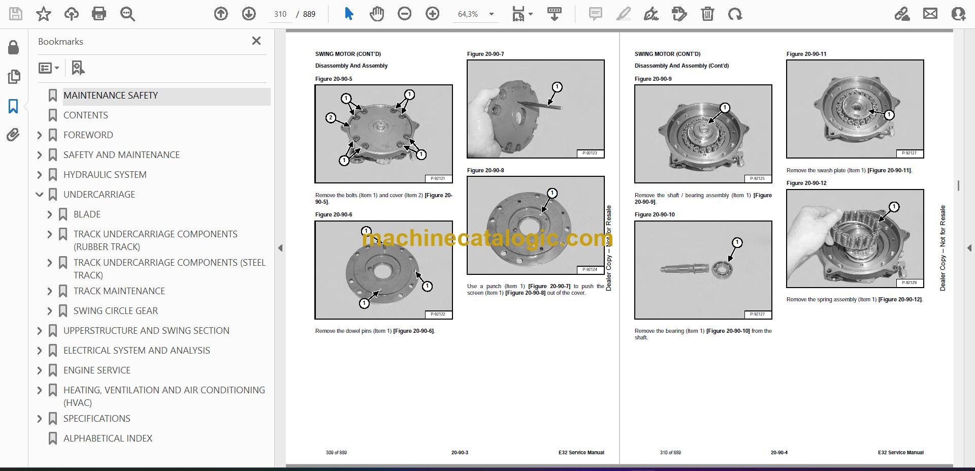
Q: Is this a searchable PDF and are the wiring diagrams readable?

A: Yes, these manuals are usually searchable PDFs and the wiring diagrams are laid out so you can zoom in and read connector labels.

Q: How do I know if it fits my exact E32?

A: Check the serial plate on your machine; if it falls between B2VV11001 and B2VV99999, this is the right manual range.

Q: Is this the right document if I'm just doing routine maintenance?

A: It will cover that, but it's really built for repair and diagnostics. For simple service intervals and greasing, the operator's handbook is easier to use.

If your E32's serial number is in that B2VV range and you're doing real repair work, this is the manual you want in the truck or on the bench.

📘 Show Index

Table of Contents:

  • MAINTENANCE SAFETY
  • CONTENTS
  • FOREWORD
    • FOREWORD
    • SAFETY INSTRUCTIONS
    • FIRE PREVENTION
      • Maintenance
      • Operation
      • Electrical
      • Hydraulic System
      • Fueling
      • Starting
      • Spark Arrester Exhaust System
      • Welding And Grinding
      • Fire Extinguishers
    • SERIAL NUMBER LOCATIONS
      • Excavator Serial Number
      • Engine Serial Number
    • DELIVERY REPORT
    • EXCAVATOR IDENTIFICATION
  • SAFETY AND MAINTENANCE
    • LIFTING AND BLOCKING THE EXCAVATOR
      • Procedure
    • LIFTING THE EXCAVATOR
      • Procedure
    • OPERATOR CAB (ROPS / TOPS)
      • Description
      • Cab Door
      • Front Window
      • Front Wiper
      • Window Washer Reservoir
      • Right Side Window
    • OPERATOR CANOPY (ROPS / TOPS)
      • Description
    • TRANSPORTING THE EXCAVATOR ON A TRAILER
      • Loading And Unloading
      • Fastening
    • TAILGATE
      • Opening And Closing
      • Adjusting The Latch
    • RIGHT SIDE COVER
      • Opening And Closing
    • SERVICE SCHEDULE
      • Maintenance Intervals
    • AIR CLEANER SERVICE
      • Daily Check
      • Replacing The Filters
    • CAB FILTERS
      • Cleaning And Maintenance
    • ENGINE COOLING SYSTEM
      • Cleaning
      • Checking Level
      • Removing And Replacing Coolant
    • FUEL SYSTEM
      • Fuel Specifications
      • Biodiesel Blend Fuel
      • Filling The Fuel Tank
      • Fuel Filters
      • Removing Air From The Fuel System
      • Draining The Fuel Tank
    • ENGINE LUBRICATION SYSTEM
      • Checking And Adding Engine Oil
      • Engine Oil Chart
      • Removing And Replacing Oil And Filter
    • HYDRAULIC SYSTEM
      • Checking And Adding Hydraulic Fluid
      • Hydraulic / Hydrostatic Fluid Chart
      • Removing And Replacing Hydraulic Filters
      • Removing And Replacing The Hydraulic Fluid
    • LUBRICATION OF THE HYDRAULIC EXCAVATOR
      • Lubrication Locations
    • PIVOT PINS
      • Inspection And Maintenance
    • TRAVEL MOTOR
      • Checking And Adding Oil
      • Removing And Replacing Oil
    • EMERGENCY EXIT
      • Right Side Rear Window
      • Front Window
    • SEAT BELT
      • Inspection And Maintenance
    • CONTROL CONSOLE LOCKOUTS
      • Inspection And Maintenance
    • TOWING THE EXCAVATOR
      • Procedure
    • REMOTE START TOOL KIT – MEL1563
      • Remote Start Tool Kit – MEL1563
      • Service Tool Harness Control – MEL1565
      • Service Tool Harness Communicator – MEL1566
    • REMOTE START TOOL (SERVICE TOOL) KIT – 7217666
      • Description
      • Remote Start Tool (Service Tool) – 7022042
      • Excavator Service Tool Harness – 6689747
      • Computer Service Tool Harness – 6689746
  • HYDRAULIC SYSTEM
    • HYDRAULIC / HYDROSTATIC SCHEMATICS
    • HYDRAULIC SYSTEM INFORMATION
      • Glossary Of Hydraulic / Hydrostatic Symbols
      • Troubleshooting The Hydraulic Circuit
      • Troubleshooting The Cylinder Circuit
      • Troubleshooting The Swing (Upperstructure Slew) Circuit
      • Troubleshooting The Travel Circuit
    • CYLINDER (BOOM)
      • Testing
      • Removal And Installation
      • Parts Identification
      • Disassembly
      • Assembly
    • CYLINDER (ARM)
      • Testing
      • Removal And Installation
      • Parts Identification
      • Disassembly
      • Assembly
    • CYLINDER (BOOM SWING)
      • Testing
      • Removal And Installation
      • Parts Identification
      • Disassembly
      • Assembly
    • CYLINDER (BUCKET)
      • Testing
      • Removal And Installation
      • Parts Identification
      • Disassembly
      • Assembly
    • CYLINDER (BLADE)
      • Testing
      • Removal And Installation
      • Parts Identification
      • Disassembly
      • Assembly
    • CYLINDER (CLAMP)
      • Testing
      • Removal And Installation
      • Parts Identification
      • Disassembly
      • Assembly
    • CYLINDER (EXTENDABLE ARM)
      • Testing
      • Parts Identification
      • Disassembly
      • Assembly
    • VALVE (MAIN RELIEF)
      • Description
    • VALVE (PORT RELIEF)
      • Testing And Adjusting Port Relief Valve Pressure
    • VALVE (CROSS PORT RELIEF)
      • Testing
      • Removal And Installation
      • Cross Port Relief Valve Disassembly And Assembly
    • VALVE (PILOT PRESSURE RELIEF)
      • Testing And Adjusting The Pilot Pressure Relief Valve
    • HYDRAULIC CONTROL VALVE
      • Description
      • Removal And Installation
      • Parts Identification
      • Disassembly
      • Assembly
      • Inlet Valve Section Disassembly And Assembly
      • Boom Swing Valve Section Disassembly And Assembly
      • Slew Valve Section Disassembly And Assembly
      • Blade Valve Section Disassembly And Assembly
      • Right And Left Travel Valve Section Disassembly And Assembly
      • Boom Valve Section Disassembly And Assembly
      • Auxiliary, Arm, Bucket And Angle Blade Valve Section Disassembly And Assembly
      • Outlet Valve Section Disassembly And Assembly
    • HYDRAULIC PUMP
      • Hydraulic Pump Work Sheet
      • Pump Testing
      • Description
      • Removal And Installation
      • Coupler Removal And Installation
      • Hydraulic Pump Startup
      • Gear Pump Disassembly And Assembly
      • Piston Pump Parts Identification
      • Piston Pump Disassembly And Assembly
    • MANIFOLD ASSEMBLY / ACCUMULATOR
      • Description
      • Removal And Installation
      • Parts Identification
      • Disassembly And Assembly
    • TRAVEL MOTOR
      • Removal And Installation
      • Parts Identification Hydraulic Motor
      • Parts Identification Gear Reduction Hub
      • Disassembly
      • Assembly
    • SWIVEL JOINT
      • Removal And Installation
      • Parts Identification Earlier Model Swivel
      • Parts Identification Later Model Swivel
      • Disassembly And Assembly
    • SWING MOTOR
      • Removal And Installation
      • Parts Identification
      • Disassembly And Assembly
    • SWING MOTOR (DRIVE CARRIER)
      • Removal And Installation
      • Parts Identification
      • Disassembly And Assembly
    • CONTROL PATTERN SELECTOR VALVE
      • Removal And Installation
      • Parts Identification
      • Disassembly And Assembly
    • RIGHT CONTROL LEVER (JOYSTICK)
      • Testing
      • Handle Removal And Installation
      • Joystick Assembly Removal And Installation
      • Parts Identification
      • Disassembly
      • Assembly
    • LEFT CONTROL LEVER (JOYSTICK)
      • Testing
      • Handle Removal And Installation
      • Joystick Assembly Removal And Installation
      • Parts Identification
      • Disassembly
      • Assembly
    • HYDRAULIC FILTER MOUNT
      • Removal And Installation
    • HYDRAULIC RESERVOIR
      • Removal And Installation
    • OIL COOLER
      • Removal And Installation
    • DIRECT TO TANK VALVE
      • Removal And Installation
    • BLADE CONTROL LEVER
      • Handle Removal And Installation
      • Removal And Installation
      • Parts Identification
      • Disassembly And Assembly
    • CASE DRAIN FILTER MOUNT
      • Removal And Installation
    • TRAVEL CONTROL VALVE
      • Removal And Installation
      • Parts Identification
      • Disassembly And Assembly
    • REMOVING AIR FROM THE HYDRAULIC SYSTEM
      • Procedure
    • HYDRAULIC X-CHANGE MANIFOLD (EARLIER MODEL)
      • Removal And Installation
      • Parts Identification
      • Disassembly And Assembly
    • HYDRAULIC X-CHANGE MANIFOLD (LATER MODEL)
      • Removal And Installation
      • Parts Identification
      • Disassembly And Assembly
    • SECONDARY AUXILIARY VALVE (EARLIER MODEL)
      • Removal And Installation
      • Parts Identification
      • Disassembly And Assembly
    • SECONDARY AUXILIARY VALVE (LATER MODEL)
      • Removal And Installation
      • Parts Identification
      • Disassembly And Assembly
    • VALVE (BOOM LOCK)
      • Removal And Installation
    • VALVE (ARM LOCK)
      • Removal And Installation
  • UNDERCARRIAGE
    • BLADE
      • Removal And Installation
    • TRACK UNDERCARRIAGE COMPONENTS (RUBBER TRACK)
      • Description
      • Track Lug Height
      • Checking Tension
      • Adjusting Tension
      • Track Removal And Installation
      • Idler Removal And Installation
      • Parts Identification
      • Idler Disassembly
      • Idler Assembly
      • Track Tensioner Removal And Installation
      • Track Tensioner Parts Identification
      • Track Tensioner Disassembly And Assembly
      • Roller Removal And Installation
      • Sprocket Removal And Installation
    • TRACK UNDERCARRIAGE COMPONENTS (STEEL TRACK)
      • Description
      • Checking Tension
      • Adjusting Tension
      • Track Removal And Installation
      • Idler Removal And Installation
      • Idler Parts Identification
      • Idler Disassembly
      • Idler Assembly
      • Track Tensioner Removal And Installation
      • Track Tensioner Parts Identification
      • Track Tensioner Disassembly And Assembly
      • Roller Removal And Installation
      • Sprocket Removal And Installation
      • Guide Plate Removal And Installation
    • TRACK MAINTENANCE
      • Track Damage Identification
    • SWING CIRCLE GEAR
      • Swing Bearing Removal
      • Swing Bearing Installation
  • UPPERSTRUCTURE AND SWING SECTION
    • UPPERSTRUCTURE
      • Removal
      • Installation
    • ROPS CANOPY
      • Removal And Installation
    • CAB
      • Removal And Installation
      • Door Removal And Installation
      • Front Window Removal And Installation
      • Front Window Disassembly And Assembly
      • Front Window Adjustment
      • Right Side Rear Sliding Window Removal And Installation
      • Right Side Front Sliding Window Removal And Installation
      • Right Side Front And Rear Sliding Window Weather Strip Removal And Installation
      • Right Side Front And Rear Sliding Window Wiper Strip Removal And Installation
      • Glass Removal
      • Glass Installation
    • SEAT
      • Removal And Installation
      • Seat Mount Removal And Installation
    • RIGHT CONSOLE
      • Console Cover Removal And Installation
    • LEFT CONSOLE
      • Lower Console Cover Removal And Installation
      • Upper Console Cover Removal And Installation
      • Compression Spring Removal And Installation
      • Lock Lever Removal And Installation
      • Console Removal And Installation
    • LEFT UPPERSTRUCTURE COVER
      • Removal And Installation
    • RIGHT UPPERSTRUCTURE COVER
      • Removal And Installation
    • COUNTERWEIGHT
      • Removal And Installation
      • Long Arm Counterweight Removal And Installation
    • TRAVEL LEVERS AND PEDALS
      • Removal And Installation
      • Disassembly And Assembly
    • FLOOR MAT
      • Removal And Installation
    • FUEL TANK
      • Removal And Installation
      • Fuel Tank Fitting Removal And Installation
    • HORN
      • Removal And Installation
    • SWING FRAME
      • Removal And Installation
      • Boom Swing Frame Hose Routing
      • Bushing Removal
      • Bushing Installation
    • BOOM
      • Removal And Installation
    • ARM (STANDARD AND LONG)
      • Removal And Installation
      • Arm To Boom Bushing Removal And Installation
      • Arm To Bucket And Bucket Link Bushing Removal And Installation
    • ARM (EXTENDABLE)
      • Removal And Installation
      • Arm To Boom Bushing Removal And Installation
      • Arm To Bucket Bushing Removal And Installation
      • Disassembly And Assembly
      • Shimming Procedure
    • BUCKET
      • Bucket Teeth Removal And Installation
      • Bucket Side Cutting Edge Removal And Installation
    • CLAMP
      • Removal And Installation
    • TAILGATE
      • Removal And Installation
      • Latch Removal And Installation
    • X-CHANGE
      • Removal And Installation
      • Disassembly
      • Assembly
    • X-CHANGE (HYDRAULIC)
      • Removal And Installation
      • Parts Identification
      • Disassembly
      • Assembly
    • QUICK COUPLER (KLAC™ SYSTEM)
      • Troubleshooting
      • Daily Inspection
      • Removal And Installation
      • Parts Identification
      • Disassembly
      • Assembly
    • QUICK COUPLER (LEHNHOFF® SYSTEM)
      • Troubleshooting
      • Daily Inspection
      • Removal (MS03 And MS08)
      • Installation (MS03 And MS08)
      • Parts Identification (MS03)
      • Disassembly And Assembly (MS03)
      • Parts Identification (MS08)
      • Disassembly (MS08)
      • Assembly (MS08)
    • RIGHT SIDE COVER
      • Removal And Installation
      • Latch Removal And Installation
      • Latch Adjustment
    • TOOL BOX
      • Removal And Installation
  • ELECTRICAL SYSTEM AND ANALYSIS
    • ELECTRICAL SCHEMATICS
    • ELECTRICAL SYSTEM INFORMATION
      • Troubleshooting Chart
      • Description
      • Fuse And Relay Location / Identification
    • BATTERY
      • Servicing
      • Removal And Installation
      • Using A Booster Battery (Jump Starting)
    • ALTERNATOR
      • Belt Adjustment
      • Belt Replacement
      • Charging System Inspection
      • Alternator Voltage Testing
      • Low Voltage Testing
      • High Voltage Testing
      • Removal And Installation
      • Parts Identification
    • STARTER
      • Testing
      • Removal And Installation
      • Parts Identification
    • LIGHTS
      • Removal And Installation
      • Boom Light Removal And Installation
      • Boom Light Bulb Replacement
    • MAGNETIC LOCKOUT SENSOR
      • Removal And Installation
    • FUEL LEVEL SENDER
      • Removal And Installation
      • Testing
    • DIAGNOSTIC SERVICE CODES
      • Viewing Service Codes
      • Service Codes List
    • CONTROL PANEL SETUP
      • Panel Setup (Deluxe Instrument Panel)
      • Password Setup (Keyless Start Panel)
      • Password Setup (Deluxe Instrument Panel)
      • Maintenance Clock
    • INSTRUMENT PANEL
      • Removal And Installation
    • CONTROLLER
      • Description
      • Gateway Controller Removal And Installation
      • Auxiliary Controller Removal And Installation
    • KEY SWITCH
      • Removal And Installation
    • WIPER MOTOR
      • Removal And Installation
    • MOTION ALARM SYSTEM
      • Description
      • Inspecting
      • Adjusting Switch Position
    • SERVICE PC (LAPTOP COMPUTER)
      • Connecting The Remote Start Tool
      • Connecting Remote Start Tool (Service Tool)
    • SHUT-OFF SWITCH
      • Description
      • Removal And Installation
    • TRAVEL MOTOR AUTO-SHIFT
      • Auto-Shift Drive System (If Equipped)
      • Troubleshooting
    • ENGINE SPEED CONTROL
      • Removal And Installation
    • AUTO IDLE PRESSURE SENSOR
      • Description
      • Removal And Installation
  • ENGINE SERVICE
    • ENGINE INFORMATION
      • Description
      • Specifications
      • Sensor Location
      • Torque Values
      • Troubleshooting
      • Engine Removal And Installation
    • DIESEL OXIDATION CATALYST (DOC)
      • Removal And Installation
    • AIR CLEANER
      • Housing Removal And Installation
    • ENGINE COOLING SYSTEM
      • Radiator Removal And Installation
      • Fan Removal And Installation
      • Water Pump Removal And Installation
      • Thermostat Housing Removal And Installation
      • Testing The Thermostat
    • LUBRICATION SYSTEM
      • Description
      • Oil Pan Removal And Installation
      • Oil Pump Removal And Installation
      • Oil Pump Relief Valve Description
      • Oil Pump Relief Valve Removal And Installation
      • Oil Cooler Removal And Installation
      • Oil Filter Head Removal And Installation
      • Oil Cooler Bypass Description
      • Oil Cooler Bypass Removal And Installation
    • FUEL SYSTEM
      • Description
      • Transfer Pump / High Pressure Pump Removal And Installation
      • Fuel Cooler Removal And Installation
      • Fuel Bypass Valve Removal And Installation
      • Fuel Recirculation Valve Removal And Installation
      • Fuel Injector Removal And Installation
      • Removing Air From The Fuel System
    • CYLINDER HEAD
      • Glow Plugs Testing
      • Glow Plug Removal And Installation
      • Valve Clearance Adjustment
      • Cylinder Head Removal And Installation
      • Cylinder Head Disassembly And Assembly
      • Cylinder Head Inspection
      • Cylinder Head Top Clearance
      • Valve Step Height
      • Valve Stem Height
      • Valve Guide
      • Valve
      • Valve Spring
      • Rocker Arm Shaft Disassembly And Assembly
      • Rocker Arm Shaft Inspection
      • Push Rod Inspection
    • CRANKSHAFT AND PISTONS
      • Piston And Connecting Rod Removal And Installation
      • Piston And Connecting Rod Inspection
      • Crankshaft Removal And Installation
      • Cylinder Block Inspection
      • Crankshaft Inspection
      • Connecting Rod Inspection
      • Engine Component Class
    • CAMSHAFT
      • Removal And Installation
      • Inspecting
    • GEARCASE
      • Gearcase Cover Removal And Installation
      • Gear Backlash
      • Gear Timing
      • Idle Gear Removal And Installation
      • Idle Gear Inspection
    • TURBOCHARGER
      • Description
      • Removal And Installation
      • Inspection
    • FLYWHEEL AND HOUSING
      • Hydraulic Pump Coupler Removal And Installation
      • Flywheel Removal And Installation
      • Ring Gear Removal And Installation
    • EXHAUST GAS RECIRCULATION (EGR) SYSTEM
      • Valve Removal And Installation
      • Cooler Removal And Installation
    • INTERCOOLER
      • Description
      • Removal And Installation
  • HEATING, VENTILATION AND AIR CONDITIONING (HVAC)
    • AIR CONDITIONING SYSTEM FLOW
      • Description
      • Chart
      • Components
      • Safety Equipment
    • REGULAR MAINTENANCE
      • Cab Filters
      • Air Conditioning Compressor Belt Adjustment
      • Air Conditioning Compressor Belt Replacement
      • Condenser
      • Air Conditioning Lubrication
      • Evaporator / Heater Coil
      • Air Conditioning Service Chart
    • TROUBLESHOOTING
      • Blower Motor Does Not Operate
      • Blower Motor Operates Normally, But Air Flow Is Insufficient
      • Insufficient Cooling Although Air Flow And Compressor Operation Are Normal
      • The Compressor Operates Improperly Or Not At All
      • Gauge Pressure Related Troubleshooting
      • Temperature / Pressure Chart
      • Poor A/C Performance
      • HVAC Repair And Leaks
      • Electrical System
      • Engine Coolant Bypassing The Heater Valve
    • SYSTEM CHARGING AND RECLAMATION
      • Refrigerant Identification
      • Reclamation And Charging With Recovery / Charging Unit
    • COMPRESSOR
      • Removal And Installation
      • Oil
      • Oil Check
    • CONDENSER
      • Removal And Installation
    • RECEIVER / DRIER
      • Receiver / Drier Removal And Installation
      • Pressure Switch Removal And Installation
    • EVAPORATOR / HEATER UNIT
      • Removal And Installation
    • THERMOSTAT
      • Description
      • Removal And Installation
    • EXPANSION VALVE
      • Removal And Installation
    • EVAPORATOR COIL
      • Removal And Installation
    • HEATER COIL
      • Removal And Installation
    • BLOWER FAN
      • Removal And Installation
    • HEATER VALVE
      • Removal And Installation
    • HVAC DUCT
      • Removal And Installation
  • SPECIFICATIONS
    • EXCAVATOR SPECIFICATIONS
      • Machine Dimensions
      • Machine Dimensions – Standard Arm
      • Machine Dimensions – Long Arm
      • Machine Dimensions – Extendable Arm
      • Performance
      • Engine
      • Controls
      • Hydraulic System
      • Hydraulic Cylinders
      • Hydraulic Cycle Times
      • Drive System
      • Slew System
      • Undercarriage
      • Electrical
      • Capacities
      • Tracks
      • Ground Pressure
    • TECHNICAL SERVICE GUIDE SPECIFICATIONS
      • Engine
      • Engine Torques
      • Cooling System
      • Excavator Torques
    • TORQUE SPECIFICATION FOR BOLTS
      • Torque For General SAE Bolts
      • Torque For General Metric Bolts
    • HYDRAULIC CONNECTION SPECIFICATIONS
      • O-ring Face Seal Connection
      • Straight Thread O-ring Fitting
      • Tubelines And Hoses
      • Flare Fitting
      • O-ring Flare Fitting
      • Port Seal Fitting
      • Push To Connect Fittings
    • HYDRAULIC FLUID SPECIFICATIONS
      • Specifications
    • CONVERSIONS
      • Decimal And Millimeter Equivalent Chart
      • U.S. To Metric Conversion Chart
    • SERVICE TOOLS REQUIRED
      • Remote Start Tools
      • Hydraulic Tools
      • Engine Tools
      • Electrical Tools
      • General Tools
      • HVAC Tools
  • ALPHABETICAL INDEX

Bobcat Software

Bobcat PDF Manuals

Related Manuals

0
    0
    Your Cart
    Your cart is emptyReturn to Shop