The V417 VersaHANDLER TTC is a telescopic handler you'll see loading trucks, stacking pallets, or running forks and buckets in tight farmyards and construction sites. The service manual is what I grab when I'm in a muddy customer lot with a laptop on the tire and I need the right teardown steps, test ports, and specs. People use it once the warranty's gone and they're chasing hydraulic issues, drive problems, or electrical gremlins without guessing and ordering parts twice.
What this manual helps you do
- Diagnose boom, outriggers, and steering hydraulics with proper test points and pressure checks
- Trace and troubleshoot electrical faults using clear wiring diagrams and connector callouts
- Follow step-by-step removal and installation for components like axles, boom sections, and cylinders
- Rebuild or reseal hydraulic components and set them back up with the right adjustments
- Check, adjust, and replace drivetrain and engine-related parts without tearing into the wrong area first
Who this is for
This manual is for anyone working on a Bobcat V417 VersaHANDLER TTC with a serial number between AC1C11001 and AC1C99999: small contractors, farm shops, rental fleets, field techs, and owner-operators. If you just want basic controls, safety, and daily checks, you want the operator's handbook instead, not this service manual.
FAQ
Q: Is this a searchable PDF, and can I read the wiring diagrams clearly?
A: These manuals are usually searchable PDFs, and in my experience the wiring diagrams zoom in clearly enough to read pin numbers on a laptop or tablet.
Q: How do I know it fits my exact machine?
A: Check your machine's serial plate. If it falls in the AC1C11001 to AC1C99999 range, this is the right manual family for your V417.
Q: Is this the right document if I'm doing my own repairs?
A: Yes, if you're doing real repair work or diagnostics. For parts numbers, you'd still want the separate parts catalog.
Bottom line: If you own or service a Bobcat V417 VersaHANDLER TTC in that serial range and you're turning wrenches on it, this is the manual you want.
📘 Show Index
Table of Contents:
- MAINTENANCE SAFETY
- CONTENTS
- FOREWORD
- FOREWORD
- SAFETY INSTRUCTIONS
- FIRE PREVENTION
- Maintenance
- Operation
- Electrical
- Hydraulic System
- Fueling
- Starting
- Spark Arrestor Exhaust System
- Welding And Grinding
- Fire Extinguishers
- SERIAL NUMBER LOCATION
- VersaHANDLER Serial Number
- Engine Serial Number
- Other Serial Numbers
- DELIVERY REPORT
- VersaHANDLER IDENTIFICATION
- SAFETY & MAINTENANCE
- LIFTING AND BLOCKING THE VERSAHANDLER
- OPERATOR CAB / CANOPY
- TRANSPORTING THE VERSAHANDLER ON A TRAILER
- Loading And Unloading
- Fastening
- TOWING THE VersaHANDLER
- Releasing The Brake Discs
- Towing
- Engaging The Brake Discs
- SERVICE SCHEDULE
- AIR CLEANER SERVICE
- Replacing The Filter Element
- ENGINE COOLING SYSTEM
- Cleaning
- Removing And Replacing The Coolant
- Checking Level
- FUEL SYSTEM
- Fuel Specifications
- Filling The Fuel Tank
- Fuel Filter
- ENGINE LUBRICATION SYSTEM
- Checking Engine Oil
- Oil Chart
- Replacing Oil And Filter
- HYDRAULIC / HYDROSTATIC SYSTEM
- Checking And Adding Fluid
- Replacing The Hydraulic / Hydrostatic Filters
- Replacing Hydraulic Fluid
- AXLES (FRONT AND REAR)
- Checking Oil Level (Planetary Carrier)
- Draining Oil (Planetary Carrier)
- Checking Oil Level (Rear Differential)
- Draining Oil (Rear Differential)
- Checking Oil Level (Front Differential)
- Draining Oil (Front Differential)
- LUBRICATION
- TIRE MAINTENANCE
- Wheel Nuts
- Tire Mounting
- Tire Rotation
- Tire Pressure
- SPARK ARRESTOR MUFFLER
- APPROVED BOOM STOP
- ENGINE COVER
- Opening And Closing The Engine Cover
- LATERAL OPERATOR RESTRAINT SYSTEM (LORS)
- System Inspection
- System Maintenance
- REMOTE START
- Connecting to the VersaHANDLER
- Remote Start Procedure (For Tools MEL1563 And MEL1565)
- Remote Start Procedure (For Tool Kit P/N 6689779)
- VersaHANDLER STORAGE AND RETURN TO SERVICE
- Storage
- Return To Service
- STOPPING THE ENGINE AND LEAVING THE VERSAHANDLER
- EMERGENCY EXIT
- HYDRAULIC SYSTEM
- HYDRAULIC / HYDROSTATIC SCHEMATICS
- HYDRAULIC SYSTEM INFORMATION
- Glossary Of Hydraulic / Hydrostatic Symbols
- Troubleshooting Chart
- Tightening Procedures
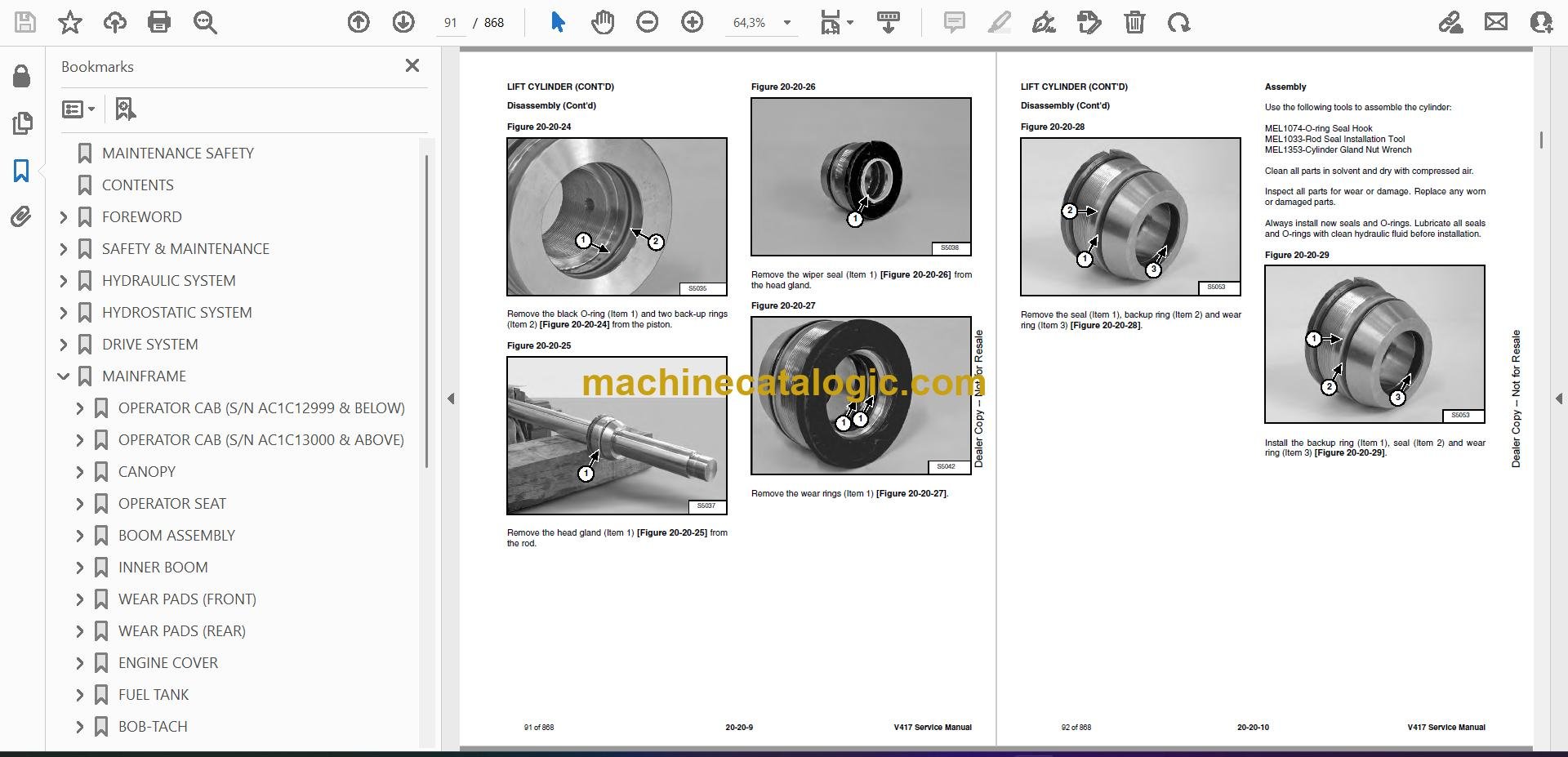
- LIFT CYLINDER
- Removal And Installation
- Parts Identification
- Disassembly
- Assembly
- BUCKET POSITIONING CYLINDER
- Removal And Installation
- Parts Identification
- Disassembly
- Assembly
- EXTENSION CYLINDER
- Cylinder Group Removal And Installation
- Upper Tubeline Removal
- Upper Tubeline Installation
- Extension Cylinder Removal And Installation
- Tubeline Tray Disassembly
- Tubeline Tray Assembly
- Parts Identification
- Disassembly
- Assembly
- TILT CYLINDER
- Removal And Installation
- Parts Identification
- Disassembly
- Assembly
- STEERING CYLINDER (FRONT)
- Removal
- Installation
- Parts Identification
- Disassembly
- Assembly
- STEERING CYLINDER (REAR)
- Removal
- Installation
- Parts Identification
- Disassembly
- Assembly
- DRIVE BOX
- Parts Identification
- Disassembly
- Assembly
- Special Tools
- MAIN RELIEF VALVE
- Testing And Adjustment
- Removal And Installation
- PORT RELIEF VALVES
- Parts Identification
- Adjustment Procedure
- STEERING MODE VALVE BLOCK
- Removal And Installation
- Parts Identification
- Disassembly
- Solenoid Testing
- Assembly
- BRAKE VALVE
- Removal And Installation
- Disassembly And Assembly
- GEAR PUMP
- Removal And Installation
- Parts Identification
- Disassembly And Assembly
- HYDRAULIC RESERVOIR
- STEERING VALVE
- Removal And Installation
- Parts Identification
- Disassembly
- Inspection
- Assembly
- HYDRAULIC CONTROL VALVE
- Troubleshooting Chart (Controllers)
- Telescoping Valve Section Troubleshooting
- Auxiliary Valve Section Troubleshooting
- Troubleshooting Chart (Control Valve)
- Removal And Installation
- Parts Identification
- Disassembly And Assembly
- End Housing Disassembly And Assembly
- Telescoping and Auxiliary Valve Section Disassembly And Assembly
- Lifting and Tilting Valve Section Disassembly And Assembly
- Inlet-Outlet Valve Section Disassembly And Assembly
- JOYSTICK
- PARKING BRAKE
- Parking And Passive Brake Switch Removal And Installation
- Parking And Passive Brake Switch Disassembly And Assembly
- WORKGROUP LOCKOUT VALVE
- Testing
- Removal And Installation
- Disassembly And Assembly
- TOW VALVE
- Removal And Installation
- Disassembly And Assembly
- FRONT AUXILIARY HYDRAULIC PRESSURE RELEASE VALVE
- Removal And Installation
- Disassembly And Assembly
- MANIFOLD
- Removal And Installation
- Disassembly
- HYDROSTATIC SYSTEM
- HYDROSTATIC SYSTEM INFORMATION
- Troubleshooting Chart
- Replenishing Valve Function
- OIL COOLER
- HYDROSTATIC DRIVE MOTOR
- Removal And Installation
- Parts Identification
- Disassembly
- Inspection
- Assembly
- HYDROSTATIC PUMP (S/N AC1C11001 – AC1C11999, AC1D11001 – AC1D11999)
- Removal And Installation
- Parts Identification
- Disassembly
- Inspection
- Assembly
- HYDROSTATIC PUMP (S/N AC1C12000 & ABOVE, AC1D12000 & ABOVE)
- Removal And Installation
- Parts Identification
- Shaft Disassembly
- Relief Valves Disassembly And Assembly
- Charge Pump Disassembly
- Piston Pump Disassembly
- Solenoid Block Disassembly
- Inspection
- Piston Pump Assembly
- Charge Pump Assembly
- Solenoid Block Assembly
- Shaft Assembly
- DRIVE BELT
- Description
- Shield Removal And Installation
- Adjusting
- Belt Removal And Installation
- Tensioner Pulley Removal And Installation
- Tensioner Pulley Parts Identification
- Tensioner Pulley Disassembly And Assembly
- DRIVE SYSTEM
- TROUBLESHOOTING
- AXLE AND DIFFERENTIAL (FRONT)
- Description
- Planetary Carrier And Wheel Hub Parts Identification
- Planetary Carrier Disassembly
- Wheel Hub Disassembly
- Steering Knuckle and Drive Shaft Parts Identification
- Steering Knuckle Disassembly
- Axle Housing / Drive Shaft Disassembly
- Brake Group Parts Identification
- Brake Group Disassembly
- Differential Parts Identification
- Differential Disassembly
- Pinion Group Parts Identification
- Pinion Group Disassembly
- Pinion Group Assembly
- Differential Assembly
- Brake Group Assembly
- Axle Housing / Drive Shaft Assembly
- Steering Knuckle Assembly
- Wheel Hub Assembly
- Planetary Carrier Assembly
- Special Tools
- AXLE AND DIFFERENTIAL (REAR)
- Description
- Planetary Carrier And Wheel Hub Parts Identification
- Planetary Carrier Disassembly
- Wheel Hub Disassembly
- Steering Knuckle and Drive Shaft Parts Identification
- Steering Knuckle Disassembly
- Axle Housing / Drive Shaft Disassembly
- Differential Parts Identification
- Pinion Group Parts Identification
- Pinion Group Disassembly
- Pinion Group Assembly
- Differential Assembly
- Steering Knuckle Assembly
- Wheel Hub Assembly
- Planetary Carrier Assembly
- Special Tools
- FRONT AXLE
- AXLE TOE-IN
- PARKING BRAKE
- Releasing The Brake Discs
- Engaging The Brake Discs
- STEERING ANGLE ADJUSTMENT
- DRIVE SHAFT
- SERVICE BRAKE
- Description
- Bleeding The Brake Circuit
- REAR AXLE
- MAINFRAME
- OPERATOR CAB (S/N AC1C12999 & BELOW)
- OPERATOR CAB (S/N AC1C13000 & ABOVE)
- CANOPY
- OPERATOR SEAT
- Removal And Installation
- Disassembly And Assembly
- BOOM ASSEMBLY
- INNER BOOM
- WEAR PADS (FRONT)
- WEAR PADS (REAR)
- ENGINE COVER
- Locking Mechanism Removal And Installation
- Removal And Installation
- Lock
- FUEL TANK
- BOB-TACH
- Removal And Installation
- Lever And Wedge Disassembly And Assembly
- REAR WEIGHTS
- FENDER
- JOYSTICK PANEL (S/N AC1C12999 & BELOW, AC1D12999 & BELOW)
- Cover Removal and Installation
- JOYSTICK PANEL (S/N AC1C13000 & ABOVE, AC1D13000 & ABOVE)
- Cover Removal and Installation
- DASH COVER / STEERING COLUMN COVER (S/N AC1C12999 & BELOW, AC1D12999 & BELOW)
- Steering Column Cover Removal And Installation
- Dash Cover Removal And Installation
- DASH COVER / STEERING COLUMN COVER (S/N AC1C13000 & ABOVE, AC1D13000 & ABOVE)
- Dash Cover Removal And Installation
- Steering Column Cover Removal And Installation
- ELECTRICAL SYSTEM & ANALYSIS
- ELECTRICAL SCHEMATICS
- ELECTRICAL SYSTEM INFORMATION (S/N AC1C12999 & BELOW, AC1D12999 & BELOW)
- Troubleshooting Chart
- Description
- Fuses, Diodes And Relays
- ELECTRICAL SYSTEM INFORMATION (S/N AC1C13000 & ABOVE, AC1D13000 & ABOVE)
- Troubleshooting Chart
- Description
- Fuses, Diodes And Relays
- BATTERY
- Removal And Installation
- Servicing
- Using A Booster Battery (Jump Starting)
- ALTERNATOR
- Removal And Installation
- Belt Adjustment
- Belt Replacement
- STARTER
- Testing
- Removal And Installation
- Parts Identification
- LATERAL OPERATOR RESTRAINT SYSTEM (LORS)
- Restraint Bar Removal And Installation
- Sensor Removal And Installation
- Restraint Bar Bumper Removal And Installation
- LIGHTS
- Rear Light Removal And Installation
- Front Light Removal And Installation
- TRAVEL LEVER (S/N AC1C12999 & BELOW, AC1D12999 & BELOW)
- TRAVEL LEVER (S/N AC1C13000 & ABOVE, AC1D13000 & ABOVE)
- INSTRUMENT PANEL (S/N AC1C12999 & BELOW, AC1D12999 & BELOW)
- INSTRUMENT PANEL (S/N AC1C13000 & ABOVE, AC1D13000 & ABOVE)
- SWITCH PANEL (S/N AC1C13000 & ABOVE, S/N AC1D13000 & ABOVE)
- FRONT WIPER MOTOR
- TOP WIPER MOTOR
- REAR WIPER MOTOR
- PEDAL ASSEMBLY
- Removal And Installation
- Disassembly And Assembly
- INCHING SWITCH
- Removal And Installation
- Adjustment
- SERVICE SOFTWARE
- Connecting Remote Start Tool To Laptop Computer
- Connecting Remote Start Tool (Service Tool)
- Connecting Remote Start Tool To VersaHANDLER
- Entering The Service Software
- Calibrate Inch Pedal
- MAIN CONTROLLER
- Removal And Installation
- Connector Identification
- DIAGNOSTIC SERVICE CODES
- Viewing Service Codes
- Service Codes List
- ENGINE SERVICE
- ENGINE INFORMATION
- Description
- Troubleshooting
- Compression – Checking
- ENGINE AND ENGINE MOUNTS
- ENGINE AND HYDROSTAT ASSEMBLY
- ENGINE SPEED CONTROL
- MUFFLER
- AIR CLEANER
- Removal And Installation
- Air Intake Cowling Removal And Installation
- ENGINE COOLING SYSTEM
- Radiator Removal And Installation
- Fan Removal And Installation
- Water Pump Removal And Installation
- Water Pump Disassembly And Assembly
- Thermostat Housing Removal And Installation
- LUBRICATION SYSTEM
- Oil Pan Removal And Installation
- Oil Pump Removal And Installation
- Oil Pump Inspection
- Oil Filter Cooler Removal And Installation
- Engine Oil Pressure – Testing
- FUEL SYSTEM
- Fuel Camshaft Removal And Installation
- Injection Pump Governor Housing Removal And Installation
- Injection Pump Governor Housing Disassembly And Assembly
- Fuel Shutoff Solenoid – Checking
- Fuel Shutoff Solenoid Removal And Installation
- Fuel Injection Pump Removal And Installation
- Fuel Injection Pump Housing Removal
- Fuel Injection Pump Housing Installation
- Injection Pump Timing
- Fuel Injector Removal and Installation
- Fuel Injector Nozzle Pressure – Checking
- Nozzle Spraying Condition
- Valve Seat Tightness
- CYLINDER HEAD
- Intake Air Heater – Testing
- Intake Air Heater Removal And Installation
- Valve Clearance Adjustment
- Valve Timing – Checking
- Cylinder Head Removal And Installation
- Cylinder Head Disassembly And Assembly
- Cylinder Head – Servicing
- Cylinder Head Top Clearance
- Valve Guide – Checking
- Reconditioning The Valve And Valve Seat
- Valve Spring
- Valve Tappets
- Rocker Arm And Shaft – Checking
- CRANKSHAFT AND PISTONS
- Piston And Connecting Rod Removal And Installation
- Piston And Connecting Rod – Servicing
- Cylinder Bore Checking
- Connecting Rod Alignment
- Crankshaft Gear Removal And Installation
- Crankshaft And Bearings Removal and Installation
- Crankshaft And Bearings – Servicing
- CAMSHAFT AND TIMING GEARS
- Timing Gearcase Cover Removal And Installation
- Timing Gears Backlash – Checking
- Camshaft – Servicing
- Idle Gear And Shaft Removal And Installation
- Idler Gear And Shaft – Servicing
- Balancer Shaft Servicing
- TURBOCHARGER
- Description
- Testing
- Removal And Installation
- FLYWHEEL AND HOUSING
- Flywheel Removal And Installation
- Ring Gear Removal And Installation
- Housing Removal And Installation
- EXHAUST GAS RECIRCULATION (EGR) SYSTEM
- Checking The Function Of EGR System
- Disassembly And Assembly
- HEATING, VENTILATION AND AIR CONDITIONING (HVAC)
- AIR CONDITIONING SYSTEM FLOW
- COMPONENTS (S/N AC1C12999 & BELOW)
- COMPONENTS (S/N AC1C13000 & ABOVE)
- SAFETY
- REGULAR MAINTENANCE
- Filter Element Removal And Installation
- Compressor And Alternator Drive Belt Inspection
- Cleaning The Condenser
- BASIC TROUBLESHOOTING
- Poor A/C Performance
- Compressor And Alternator Drive Belt Inspection
- Checking The Electrical System
- GENERAL AIR CONDITIONING SERVICE GUIDELINES
- Compressor Oil
- Compressor Oil Check
- Component Replacement And Refrigeration Leaks
- SYSTEM TROUBLESHOOTING CHART
- Chart
- Gauge Pressure Related Troubleshooting
- TEMPERATURE AND PRESSURE
- AIR CONDITIONING SERVICE
- SYSTEM CHARGING AND RECLAMATION
- Reclamation Procedure
- Charging Procedure With A Manifold Gauge Set
- COMPRESSOR
- Removal And Installation
- Compressor Clutch Disassembly And Assembly
- CONDENSER (S/N AC1C12999 & BELOW)
- CONDENSER (S/N AC1C13000 & ABOVE)
- RECEIVER / DRIER
- PRESSURE SWITCH
- EVAPORATOR/BLOWER UNIT (S/N AC1C12999 & BELOW)
- EVAPORATOR / BLOWER UNIT (S/N AC1C13000 & ABOVE)
- EXPANSION VALVE (S/N AC1C12999 & bELOW)
- EXPANSION VALVE (S/N AC1C13000 & ABOVE)
- HEATER ASSEMBLY
- Removal And Installation
- Fan Removal And Installation
- Core Removal And Installation
- SPECIFICATIONS
- VersaHANDLER TELESCOPIC TOOL CARRIER (TTC) SPECIFICATIONS
- Machine Dimensions
- Performance
- Engine
- Controls
- Drive System
- Tires
- Capacities
- Hydraulic System
- Electrical System
- Instrument Panel
- ENGINE SPECIFICATIONS
- General
- Fuel System
- Cylinder Head
- Valve Guides
- Valve Tappets
- Exhaust Valves
- Intake Valves
- Valve Springs
- Valve Timing
- Rocker Arm
- Camshaft
- Timing Gear
- Piston And Piston Ring
- Connecting Rod
- Cylinder Bore
- Crankshaft
- Oil Pump
- Cooling System
- Intake Air Heater
- Torque Values
- Engine Torque Component
- MACHINE TORQUE SPECIFICATIONS
- TORQUE SPECIFICATIONS FOR BOLTS
- Torque for General SAE Bolts
- Torque For General Metric Bolts
- HYDRAULIC CONNECTION SPECIFICATIONS
- O-ring Face Seal Connection
- Straight Thread O-ring Fitting
- Tubelines And Hoses
- Flare Fitting
- O-ring Flare Fitting
- Port Seal Fitting
- HYDRAULIC / HYDROSTATIC FLUID SPECIFICATIONS
- CONVERSIONS
- Decimal And Millimeter Equivalent Chart
- U.S. To Metric Conversion Chart
- ALPHABETICAL INDEX
- SERVICE MANUAL REVISION
Bobcat Software
Bobcat PDF Manuals


