$ 0
0
$ 0
0

Bobcat UV34XL Utility Vehicle Service Manual (SN B4LY11001-B4LY99999)

Format: PDF (Printable Document)

File Language: English

File Pages: 523

File Size: 14.61 MB (Speed Download Link)

Brand: Bobcat

Model: UV34XL Utility Vehicle

Book No: 7361390

Serial No: SN B4LY11001-B4LY99999

Type of Document: Service Manual

Categories: ,

$ 45

Share:

Bobcat UV34XL Utility Vehicle Service Manual (SN B4LY11001-B4LY99999)

The UV34XL is the bigger Bobcat side-by-side you use for hauling seed, fencing, tools, and people around the place, and it works every day like a small truck. The service manual is what I reach for when the dash is lit up, it will not move, or I've got fluids on the floor and only a weekend to sort it out. Folks use it to see how the machine actually comes apart, what order to do things in, and what specs to check so they don't have to redo the job.

What this manual helps you do

  • Diagnose no-start, stalling, or low-power issues on the small diesel and fuel system
  • Trace electrical faults using wiring diagrams when lights, 4×4, or accessories quit
  • Check and adjust hydrostatic and drivetrain components when you lose drive or hear grinding
  • Follow step-by-step teardown and reassembly for hubs, suspension, steering, and brakes
  • Replace and set up hydraulic and utility circuits, then verify operation after repairs

Who this is for

This is for an owner-operator, farm shop, small contractor, or rental fleet tech who is actually turning wrenches on a Bobcat UV34XL. If you only want basic controls, fluid types, and safety info, you want the operator's handbook instead, not this manual.

FAQ

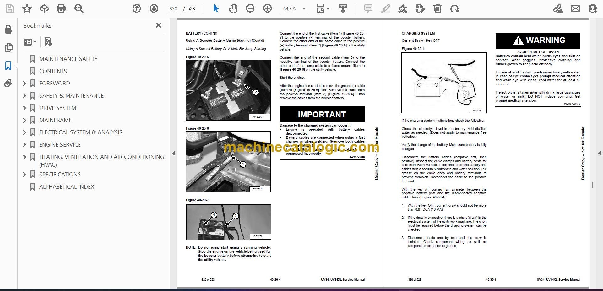
Q: Is this a searchable PDF with clear wiring diagrams?

A: Yes, these manuals are normally text searchable and the wiring diagrams are laid out so you can zoom in and read pin numbers and wire colors.

Q: How do I know if it fits my machine?

A: If your UV34XL serial number falls between B4LY11001 and B4LY99999, this is the right service manual for it.

Q: Is this what I need to do real repairs, or is it just a parts list?

A: This is the workshop-level service manual, not a parts catalog, so it covers diagnostic steps and repair procedures.

Bottom line: If you own a UV34XL in that serial range and plan to fix it yourself or in a shop, this is the manual you want. If you just drive it, you don't need this.

📘 Show Index

Table of Contents:

  • MAINTENANCE SAFETY
  • CONTENTS
  • FOREWORD
    • FOREWORD
    • SAFETY INSTRUCTIONS
    • FIRE PREVENTION
      • Maintenance
      • Operation
      • Electrical
      • Fueling
      • Starting
      • Spark Arrester Exhaust System
      • Welding And Grinding
      • Fire Extinguishers
    • SERIAL NUMBER LOCATIONS
      • Utility Vehicle Serial Number
      • Engine Serial Number
    • DELIVERY REPORT
    • (UV34) UTILITY VEHICLE IDENTIFICATION
    • (UV34XL) UTILITY VEHICLE IDENTIFICATION
  • SAFETY & MAINTENANCE
    • LIFTING AND BLOCKING THE UTILITY VEHICLE
      • Procedure
    • ROLL-OVER PROTECTIVE STRUCTURE (ROPS) / OCCUPANT PROTECTIVE STRUCTURE (OPS)
      • Description
    • TRANSPORTING THE UTILITY VEHICLE ON A TRAILER
      • Loading And Unloading
      • Fastening
    • TOWING THE UTILITY VEHICLE
      • Procedure
    • SERVICE SCHEDULE
      • Maintenance Intervals
    • AIR CLEANER SERVICE
      • Replacing Filter Element
    • ENGINE COOLING SYSTEM
      • Checking Level
      • Cleaning
      • Removing And Replacing Coolant
    • FUEL SYSTEM
      • Fuel Specifications
      • Biodiesel Blend Fuel
      • Filling The Fuel Tank
      • Fuel Filter
      • Removing Air From The Fuel System
      • Filling A Portable Fuel Container
    • ENGINE LUBRICATION SYSTEM
      • Checking And Adding Engine Oil
      • Engine Oil Chart
      • Removing And Replacing Oil And Filter
    • CONTINUOUS VARIABLE TRANSMISSION (CVT)
      • CVT Drying
      • Inspection Of The CVT
    • GEARCASE
      • Checking Transmission Fluid
      • Transmission Fluid
      • Adding Transmission Fluid
      • Removing And Replacing Transmission Fluid
      • Checking Front Gearcase Fluid
      • Front Gearcase Fluid
      • Adding Front Gearcase Fluid
      • Removing And Replacing Front Gearcase Fluid
    • TIRE MAINTENANCE
      • Tires
      • Tire Tread Depth
      • Axle And Wheel Nut Torque
      • Wheel Removal And Installation
      • Mounting
      • Tire Pressure
    • SPARK ARRESTER MUFFLER
      • Cleaning Procedure
    • UTILITY VEHICLE STORAGE AND RETURN TO SERVICE
      • Storage
      • Return To Service
    • STOPPING THE ENGINE AND LEAVING THE UTILITY VEHICLE
      • Procedure
      • Emergency Exit (When Equipped With Cab)
    • SEAT BELT
      • Inspection And Maintenance
    • LUBRICATING THE UTILITY VEHICLE
      • Lubrication Locations
  • DRIVE SYSTEM
    • BRAKE
      • General Specifications
      • Torque Specifications
      • System Service Notes
      • Noise Troubleshooting
      • System Troubleshooting
      • Hydraulic Brake System Operation
      • System Parts Identification
      • Master Cylinder Removal And Installation
      • Foot Brake Pedal Removal And Installation
      • Bleeding / Fluid Removal And Installation
      • Brake Inspection
      • Brake Pad Inspection
      • Burnishing
    • BRAKE (FRONT)
      • Pad Removal
      • Pad Inspection
      • Pad Assembly / Installation
      • Caliper Removal
      • Caliper Parts Identification
      • Caliper Disassembly
      • Caliper Inspection
      • Caliper Assembly
      • Caliper Installation
      • Disc Runout
      • Disc Inspection
      • Disc Removal And Installation
    • BRAKE (REAR)
      • Caliper Removal
      • Pad Removal
      • Pad Inspection
      • Pad Installation
      • Caliper Parts Identification
      • Caliper Disassembly
      • Caliper Inspection
      • Caliper Assembly
      • Caliper Installation
      • Disc Runout
      • Disc Inspection
      • Disc Removal And Installation
    • TRANSMISSION
      • General Operation
      • System Troubleshooting
      • Shift Lever Removal And Installation
      • Shift Cable Inspecting
      • Shift Cable Adjustment
      • Shift Cable Removal And Installation
      • Removal
      • Installation
      • Parts Identification
      • Transmission Disassembly
      • Gear Cluster Disassembly
      • Snorkel Shaft Removal / Disassembly
      • Bevel Differential Disassembly
      • Bevel Differential Assembly
      • Snorkel Gear Backlash
      • Transmission Assembly
    • DRIVE BELT
      • Removal
      • Installation
      • Belt Inspection
      • Belt Damage
    • CONTINUOUS VARIABLE TRANSMISSION (CVT)
      • CVT System Overview
      • Drive Clutch Operation
      • Driven Clutch Operation
      • CVT Break-In (Drive Belt / Clutches)
      • Maintenance And Inspection
      • Overheating Troubleshooting
      • System Troubleshooting
      • CVT Sealing, Guard And Ducting Components Parts Identification
      • CVT (Outer) Cover Removal And Installation
      • CVT (Inner) Cover Removal And Installation
    • CONTINUOUS VARIABLE TRANSMISSION (CVT) (DRIVE CLUTCH)
      • Removal And Installation
      • Spring Specifications
      • Parts Identification
      • Disassembly
      • Assembly
    • CONTINUOUS VARIABLE TRANSMISSION (CVT) (DRIVEN CLUTCH)
      • Removal And Installation
      • Parts Identification
      • Disassembly
      • Assembly
    • FINAL DRIVE
      • Description
      • Front Bearing Carrier Removal
      • Bearing Removal And Installation
      • Front Bearing Carrier Installation
      • Front Drive Shaft Removal And Installation
      • Rear Carrier Bearing Removal
      • Bearing Removal And Installation
      • Rear Bearing Carrier Installation
      • Rear Drive Shaft Removal And Installation
      • Drive Shaft / CV Joint Handling
      • Outer CV Joint And Boot Removal And Installation
      • Inner Plunging Joint And Boot Removal And Installation
      • Propshaft Removal And Installation
      • Front Gearcase Operation
      • Front Gearcase Removal And Installation
      • Front Gearcase Parts Identification
      • Front Gearcase Disassembly / Inspection
      • Front Gearcase Assembly
  • MAINFRAME
    • ROLL OVER PROTECTIVE STRUCTURE (ROPS)
      • Removal And Installation
    • SEAT
      • Seat Back Removal And Installation
      • Seat Plate Removal And Installation
      • Operator Seat Base Removal And Installation
      • Passenger Seat Base Removal And Installation
      • Seat Belt Removal And Installation
    • DASH
      • Front Access Cover Removal And Installation
      • Upper Dash Panel Removal And Installation
      • Control Panel Removal And Installation
      • Storage Panel Removal And Installation
      • Lower Dash Panel Removal And Installation
      • Instrument Cluster Cover Removal And Installation
      • Upper Center Storage Cover Removal And Installation
    • BUMPER COVER
      • Removal And Installation
    • STABILIZER BAT
      • Stabilizer Bar Removal And Installation
    • STEERING COLUMN
      • Description
      • Tilt Steering Shock Removal And Installation
      • Parts Identification
      • Steering Wheel Removal And Installation
      • Steering Wheel / Upper Steering Shaft Removal And Installation
      • Steering Shaft Bearing Replacement
      • Power Steering Unit Removal
      • Power Steering Unit Installation
    • STEERING BOX
      • Removal And Installation
    • FUEL TANK
      • Removal And Installation
    • SHOCKS
      • Rear Shock Removal And Installation
      • Front Shock Removal And Installation
      • Shock Spring Removal And Installation
    • A-ARMS
      • Front Lower A-Arm Removal And Installation
      • Front Upper A-Arm Removal
      • Front Upper A-Arm Installation
      • Rear Lower A-Arm Removal
      • Lower Rear A-Arm Installation
      • Rear Upper A-Arm Removal
      • Rear Upper A-Arm Installation
      • Inspection
      • Ball Joint Removal And Installation
    • TIE ROD
      • Description
      • Removal And Installation
      • Toe Adjustment Procedure
    • TAILGATE
      • Removal And Installation
      • Latch Removal And Installation
    • CARGO BOX
      • Removal And Installation
    • FENDER
      • Upper Fender Removal And Installation
      • Lower Fender Removal And Installation
      • Fender Flare Removal And Installation
    • ROCKER PANEL
      • Removal And Installation
    • FRONT WINDOW
      • Removal And Installation
    • DOOR
      • Removal And Installation
    • DOOR LATCH
      • Removal And Installation
      • Adjustment
    • REAR PANEL
      • Removal And Installation
    • SKID PLATE
      • Removal And Installation
    • FLOORPLATE
      • UV34
      • UV34XL
    • AIR DUCTING
      • UV34 And UV34XL Rear Removal And Installation
      • UV34XL Front Duct Removal And Installation
  • ELECTRICAL SYSTEM & ANALYSIS
    • ELECTRICAL SCHEMATIC
    • ELECTRICAL SYSTEM INFORMATION
      • Glossary Of Electrical Symbols
      • Troubleshooting
      • Description
      • Fuse And Relay Location
    • BATTERY
      • Removal And Installation
      • Servicing
      • Using A Booster Battery (Jump Starting)
    • CHARGING SYSTEM
      • Current Draw – Key OFF
      • Break Even Test
      • Alternator Removal And Installation
      • Belt Adjustment
      • Belt Replacement
    • STARTER SYSTEM
      • Operation
      • Testing
      • Removal And Installation
    • LIGHTS
      • Headlight Removal And Installation
      • Headlight Adjustment
      • Taillight / Brake Light Removal And Installation
    • ELECTRONIC CONTROL MODULE (ECU)
      • Description
      • Removal And Installation
    • VEHICLE SPEED SENSOR
      • Location
      • Testing
    • SWITCH (HEADLIGHT)
      • Location
      • Removal And Installation
      • Testing
    • SWITCH (BRAKE LIGHT)
      • Description
      • Location
      • Removal And Installation
      • Testing
    • SWITCH (AWD / 2WD / TURF)
      • Location
      • Removal And Installation
      • Testing
    • SWITCH (KEY)
      • Location
      • Removal And Installation
      • Ignition Key Switch Testing
    • SWITCH (GEAR SELECTOR)
      • Location
      • Removal And Installation
      • Testing
    • GLOW PLUGS
      • Location
      • Removal And Installation
      • Testing
    • DIFFERENTIAL SOLENOID
      • Description
      • Removal And Installation
    • DIFFERENTIAL SOLENOID (REAR RELAY)
      • Description
      • Removal And Installation
    • BACK-UP ALARM SYSTEM (IF EQUIPPED)
      • Description
      • Inspecting
      • Removal And Installation
    • TEMPERATURE SENSOR
      • Description
      • Testing
      • Removal And Installation
      • Fan Control Circuit Operation / Testing
      • Fan Control Circuit Bypass Test
    • INSTRUMENT CLUSTER
      • Indicator Lamps
      • Information Display
      • Display Area 1
      • Display Area 2
      • Check Engine Light
      • Diagnostic Trouble Codes
      • Pinouts
      • Removal And Installation
    • FUEL SENDER
      • Testing
    • DIAGNOSTIC TESTING
      • Digital Wrench™ Diagnostic Software
      • Digital Wrench™ Diagnostic Connector
      • Digital Wrench™ SmartLink Module Kit – MEL1721
      • Serial Number Location
      • Version And Update ID
      • Updates
      • Digital Wrench™ Feature Map
      • Engine Controller Reprograming (Reflash)
    • ELECTRONIC POWER STEERING (EPS)
      • EPS Operation
      • Power Steering 30A Fuse
      • System Diagnosing
      • EPS Troubleshooting (Power Steering Non-Functional With MIL ON)
      • EPS Troubleshooting (Power Steering Non-Functional With MIL OFF)
      • EPS Troubleshooting (Using Digital Wrench™)
  • ENGINE SERVICE
    • ENGINE INFORMATION
      • Description
      • Specifications
      • Torque Values
      • Troubleshooting
      • Accessible Engine Components
      • Engine Removal And Installation
      • Engine Mount Replacement
      • Compression And Leakage Test
    • THROTTLE SYSTEM
      • Throttle Pedal Removal And Installation
      • Throttle Cable Removal And Installation
      • Throttle Cable Adjustment
      • Throttle Pedal Adjustment
    • MUFFLER
      • Removal And Installation
    • AIR CLEANER
      • Housing Removal And Installation
    • ENGINE COOLING SYSTEM
      • Cooling System Pressure Test
      • Radiator Cap Pressure Test
      • System Bleeding
      • Radiator Cleaning
      • Radiator Removal And Installation
      • Cooling Fan Removal And Installation
      • Thermostat Removal And Installation
      • Water Pump Removal And Installation
    • LUBRICATION SYSTEM
      • Oil Pan Removal And Installation
      • Oil Pump Removal And Installation
      • Oil Pump Inspection
      • Engine Oil Pressure – Testing
    • FUEL SYSTEM
      • Fuel Camshaft Removal And Installation
      • Fuel Camshaft Governor Disassembly And Assembly
      • Fuel Shutoff Solenoid – Checking
      • Fuel Shutoff Solenoid Removal And Installation
      • Fuel Injection Pump Removal And Installation
      • Fuel Injection Pump – Timing
      • Fuel Injector Removal And Installation
      • Fuel Injector Nozzle Pressure – Checking
      • Nozzle Spray Condition
      • Valve Seat Tightness
      • Service Notes
      • Fuel Pump Removal And Installation
    • CYLINDER HEAD
      • Glow Plugs – Testing
      • Glow Plugs Removal And Installation
      • Valve Clearance Adjustment
      • Valve Timing – Checking
      • Cylinder Head Removal And Installation
      • Cylinder Head Disassembly And Assembly
      • Cylinder Head – Servicing
      • Cylinder Head Top Clearance
      • Valve Guide – Checking
      • Reconditioning The Valve And Valve Seat
      • Valve Spring
      • Valve Tappets
      • Rocker Arm And Shaft – Checking
    • CRANKSHAFT AND PISTONS
      • Piston And Connecting Rod Removal And Installation
      • Piston And Connecting Rod – Servicing
      • Cylinder Bore – Checking
      • Connecting Rod Alignment
      • Crankshaft Gear Removal And Installation
      • Crankshaft And Bearings Removal And Installation
      • Crankshaft And Bearings – Servicing
    • CAMSHAFT AND TIMING GEARS
      • Timing Gearcase Cover Removal And Installation
      • Timing Gears Backlash – Checking
      • Idler Gear And Shaft Removal And Installation
      • Camshaft – Servicing
      • Idler Gear And Shaft Servicing
    • FLYWHEEL
      • Flywheel Removal And Installation
      • Ring Gear Removal And Installation
  • HEATING, VENTILATION AND AIR CONDITIONING (HVAC)
    • HEATER SYSTEM
      • Description
      • Components
    • HEATER UNIT
      • Removal And Installation
    • HEATER COIL
      • Removal And Installation
    • BLOWER MOTOR
      • Removal And Installation
    • THERMOSTAT
      • Removal And Installation
    • TROUBLESHOOTING
      • Blower Motor Does Not Operate
      • Blower Motor Operates Normally, But Air Flow Is Insufficient
      • Blower Motor Does Not Operate In All Settings
      • Fan Switch Testing
      • Temperature Potentiometer Testing
      • Heater System Fuse Center
  • SPECIFICATIONS
    • UTILITY VEHICLE SPECIFICATIONS
      • Dimensions
      • Dimensions
      • Performance
      • Controls
      • Engine
      • Electrical
      • Drive System
      • Fluid And Capacities
      • Tires
    • TECHNICAL SERVICE GUIDE SPECIFICATIONS
      • Engine
      • Engine Torques
      • Cooling System
    • TORQUE SPECIFICATIONS FOR BOLTS
      • Torque For General SAE Bolts
      • Torque For General Metric Bolts
    • CONVERSIONS
      • Decimal And Millimeter Equivalent Chart
      • U.S. To Metric Conversion Chart
    • SERVICE TOOLS REQUIRED
      • Hydraulic Tools
      • Transmission / Clutch / Drive Tools
      • Engine Tools
      • HVAC Tools
  • ALPHABETICAL INDEX

Bobcat Software

Bobcat PDF Manuals

Related Manuals

0
    0
    Your Cart
    Your cart is emptyReturn to Shop