Out on a job, the S100 is a small skid-steer that sneaks into tight backyards, barns, and inside buildings for cleanup, light grading, and fork work. The people who grab this service manual are the ones actually turning wrenches: small contractors, owner-operators, and techs like me working out of a truck. They're trying to sort hydraulic issues, chase electrical gremlins, or get hard numbers before they tear into a component so they only make one parts run, not three.
What this manual helps you do
- Trace and diagnose hydraulic problems in the lift and tilt circuits when the machine gets weak or jerky
- Check and set hydrostatic and charge-related pressures with proper test ports and procedures
- Follow step-by-step removal and installation for engine, pumps, drive motors, and major components in tight spaces
- Rebuild and adjust cylinders, linkages, and Bob-Tach parts with the right sequences and specs
- Troubleshoot and repair electrical and wiring issues using readable diagrams for this exact S100 series
Who this is for
If you own or work on a Bobcat S100 in the B4KH11001-B4KH99999 serial range, this is the right workshop manual. If you only need basic controls, safety, or daily checks, you want the operator's handbook instead, not this.
FAQ
Q: Is this a searchable PDF and are the wiring diagrams readable?
A: These manuals are usually supplied as searchable PDFs, and the wiring diagrams are laid out so you can zoom in and read pin numbers and wire colors.
Q: Does this cover my exact S100?
A: If your serial number falls between B4KH11001 and B4KH99999, this is the correct manual for your machine.
Q: Is this the right document for doing real repairs?
A: Yes, this is the service manual, meant for teardown, diagnostics, and reassembly, not just basic operation or parts lookup.
Bottom line, if your S100's serial tag is in that B4KH11001-B4KH99999 window and you plan to actually repair it, this is the manual you want.
📘 Show Index
Table of Contents:
- MAINTENANCE SAFETY
- CONTENTS
- FOREWORD
- FOREWORD
- SAFETY INSTRUCTIONS
- FIRE PREVENTION
- Maintenance
- Operation
- Electrical
- Hydraulic System
- Fueling
- Starting
- Spark Arrester Exhaust System
- Welding And Grinding
- Fire Extinguishers
- SERIAL NUMBER LOCATIONS
- Loader Serial Number
- Engine Serial Number
- DELIVERY REPORT
- LOADER IDENTIFICATION
- SAFETY AND MAINTENANCE
- LIFTING AND BLOCKING THE LOADER
- LIFT ARM SUPPORT DEVICE
- OPERATOR CAB
- Description
- Raising
- Lowering
- Cab Door Sensor
- Special Applications Kit
- Special Applications Kit Inspection And Maintenance
- TRANSPORTING THE LOADER ON A TRAILER
- Loading And Unloading
- Fastening
- TOWING THE LOADER
- REMOTE START TOOL KIT – MEL1563
- Remote Start Tool – MEL1563
- Service Tool Harness Control – MEL1565
- Service Tool Harness Communicator – MEL1566
- Remote Start Procedure
- REMOTE START TOOL (SERVICE TOOL) KIT – 7217666
- Description
- Remote Start Tool (Service Tool) – 7022042
- Loader Service Tool Harness – 6689747
- Computer Service Tool Harness – 6689746
- Remote Start Procedure
- SERVICE SCHEDULE
- AIR CLEANER SERVICE
- Replacing Filter Elements
- ENGINE COOLING SYSTEM
- Cleaning
- Checking Level
- Removing And Replacing Coolant
- FUEL SYSTEM
- Fuel Specifications
- Biodiesel Blend Fuel
- Filling The Fuel Tank
- Fuel Filter
- Removing Air From The Fuel System
- ENGINE LUBRICATION SYSTEM
- Checking And Adding Engine Oil
- Engine Oil Chart
- Removing And Replacing Oil And Filter
- HYDRAULIC / HYDROSTATIC SYSTEM
- Checking And Adding Fluid
- Hydraulic / Hydrostatic Fluid Chart
- Removing And Replacing Hydraulic Fluid
- Removing And Replacing Hydraulic / Hydrostatic Filter
- Removing And Replacing Case Drain Filters
- Removing And Replacing Hydraulic Charge Filter
- Breather Cap
- FINAL DRIVE TRANSMISSION (CHAINCASE)
- Checking And Adding Oil
- Removing And Replacing Oil
- BOB-TACH (HAND LEVER)
- Inspection And Maintenance
- BOB-TACH (POWER)
- Inspection And Maintenance
- LUBRICATING THE LOADER
- TIRE MAINTENANCE
- Wheel Nuts
- Rotating
- Mounting
- SPARK ARRESTER MUFFLER
- PIVOT PINS
- Inspection And Maintenance
- LOADER STORAGE AND RETURN TO SERVICE
- Storage
- Return To Service
- STOPPING THE ENGINE AND LEAVING THE LOADER
- EMERGENCY EXIT
- SEAT BELT
- Inspection And Maintenance
- HYDRAULIC SYSTEM
- HYDRAULIC / HYDROSTATIC SCHEMATICS
- HYDRAULIC SYSTEM INFORMATION
- Glossary Of Hydraulic / Hydrostatic Symbols
- Troubleshooting
- CYLINDER (LIFT)
- Testing
- Removal And Installation
- Parts Identification
- Disassembly And Assembly
- CYLINDER (TILT)
- Testing
- Removal And Installation
- Rod End Pivot Pin Bushing And Seal Removal And Installation
- Base End Pivot Pin Removal And Installation
- Parts Identification
- Disassembly And Assembly
- CYLINDER (BOB-TACH)
- Testing
- Removal And Installation
- Parts Identification
- Disassembly And Assembly
- MAIN RELIEF VALVE
- Description
- Testing
- Adjusting
- Removal And Installation
- MAIN RELIEF VALVE (SJC)
- Description
- Testing
- Adjusting
- Removal And Installation
- HYDRAULIC CONTROL VALVE
- Description
- Removal And Installation
- Identification Chart
- BICS™ Load Check Valve Removal And Installation
- Load Check Valve Removal And Installation (Tilt And Auxiliary)
- Anti-Cavitation Valve Removal And Installation (Lift, Rod End)
- Port Relief / Anti-Cavitation Valve Removal And Installation (Lift, Base End)
- Port Relief / Anti-Cavitation Valve Removal And Installation (Tilt, Base End)
- Port Relief / Anti-Cavitation Valve Removal And Installation (Tilt, Rod End)
- Port Relief / Anti-Cavitation Valve Removal And Installation
- Plug Removal And Installation
- Rubber Boot Removal And Installation
- End Cap / Spool Lock Block Removal And Installation
- Lift Spool And Detent Removal And Installation
- Tilt Spool Removal And Installation
- Auxiliary Spool Removal And Installation
- Solenoid Removal And Installation
- Lock Valve Removal And Installation
- Lift Arm Bypass Orifice Removal And Installation
- Main Relief Valve Removal And Installation
- HYDRAULIC CONTROL VALVE (SJC)
- Description
- Removal And Installation
- Actuator Removal And Installation
- Identification Chart
- BICS™ Load Check Valve Removal And Installation
- Load Check Valve Removal And Installation (Tilt And Auxiliary)
- Anti-Cavitation Valve Removal And Installation (Lift, Rod End)
- Port Relief / Anti-Cavitation Valve Removal And Installation (Lift, Base End)
- Port Relief / Anti-Cavitation Valve Removal And Installation (Tilt, Base End)
- Port Relief / Anti-Cavitation Valve Removal And Installation (Tilt, Rod End)
- Port Relief / Anti-Cavitation Valve Removal And Installation
- Plug Removal And Installation
- End Cap Block Removal And Installation
- Lift Spool And Detent Removal And Installation
- Tilt Spool Removal And Installation
- Auxiliary Spool Removal And Installation
- Auxiliary Solenoid Removal And Installation
- Solenoid Removal And Installation
- Lock Valve Removal And Installation
- Lift Arm Bypass Orifice Removal And Installation
- Main Relief Valve Removal And Installation
- Check Valve Removal And Installation
- LIFT ARM BYPASS CONTROL VALVE
- Description
- Testing
- Removal And Installation
- Disassembly And Assembly
- HYDRAULIC PUMP
- Description
- Pump Test At Quick Couplers
- Direct Pump Test (Standard Section)
- Direct Pump Test (Charge Section)
- Removal And Installation
- Hydraulic Pump Startup
- Parts Identification
- Disassembly And Assembly
- HYDRAULIC PUMP (SJC)
- Description
- Pump Test At Quick Couplers
- Direct Pump Test (Standard Section)
- Removal And Installation
- Hydraulic Pump Startup
- Parts Identification
- Disassembly And Assembly
- HYDRAULIC / HYDROSTATIC FILTERS
- Description
- Housing Removal And Installation
- Charge Filter Housing Removal And Installation
- HYDRAULIC FLUID RESERVOIR
- Description
- Removal And Installation
- Hydraulic Fluid Screen
- OIL COOLER
- Description
- Removal And Installation
- BUCKET POSITION VALVE
- Description
- Solenoid Removal And Installation
- Solenoid Testing
- Removal And Installation
- Disassembly And Assembly
- FRONT AUXILIARY HYDRAULIC COUPLER BLOCK
- Description
- Removal And Installation
- FRONT AUXILIARY HYDRAULIC COUPLER BLOCK (SJC)
- Description
- Removal And Installation
- Disassembly And Assembly (FFI/FI)
- Disassembly And Assembly (FFH/FH)
- AUXILIARY HYDRAULIC INTERLOCK VALVE
- Description
- Removal And Installation
- Disassembly And Assembly
- BOB-TACH (POWER) BLOCK
- Description
- Removal And Installation
- Disassembly And Assembly
- HYDROSTATIC SYSTEM
- HYDROSTATIC SYSTEM INFORMATION
- Description
- Troubleshooting
- HYDROSTATIC MOTOR
- Description
- Removing And Replacing Oil
- Removal And Installation
- Parts Identification
- Disassembly And Assembly
- CHARGE PRESSURE
- Description
- Testing
- Sender Removal And Installation
- Adjusting
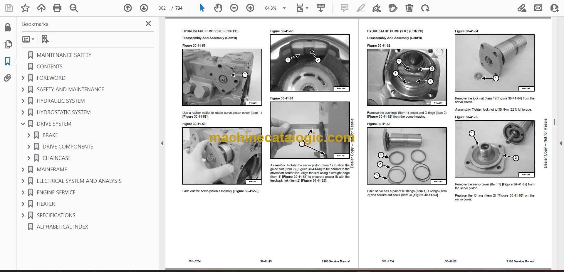
- HYDROSTATIC PUMP
- Description
- Replenishing / High Pressure Relief Valve Removal And Installation
- Removal And Installation
- Hydrostatic Pump Startup
- Parts Identification
- Disassembly
- Assembly
- HYDROSTATIC PUMP (SJC)
- Description
- Hydraulic Controller Removal And Installation
- Removal And Installation
- Hydrostatic Pump Startup
- Parts Identification
- High Pressure Relief And Bypass Valve
- Charge Relief Valve
- Disassembly And Assembly
- Mechanical Neutral Adjustment
- Hydraulic Controller Neutral Adjustment
- DRIVE BELT
- Description
- Shield Removal And Installation
- Adjusting
- Belt Removal And Installation
- Tensioner Pulley Removal And Installation
- Tensioner Pulley Disassembly And Assembly
- CASE DRAIN FILTER
- Description
- Disassembly And Assembly
- DRIVE SYSTEM
- BRAKE
- Description
- Disc Removal And Installation
- DRIVE COMPONENTS
- Description
- Axle Seal Removal And Installation
- Axle, Sprocket And Bearings Removal And Installation
- Chain Removal And Installation
- CHAINCASE
- Description
- Front Cover Removal And Installation
- Center Cover Removal And Installation
- MAINFRAME
- SEAT BAR
- Description
- Removal And Installation
- Disassembly And Assembly
- Compression Spring Disassembly And Assembly
- OPERATOR CAB
- Gas Cylinder Removal And Installation
- Gas Cylinder Bracket Disassembly And Assembly
- Removal And Installation
- OPERATOR SEAT
- Removal And Installation
- Seat Belt Removal And Installation
- OPERATOR SEAT (SUSPENSION)
- Removal And Installation
- Slide Rail Removal And Installation
- Seat Belt Removal And Installation
- Lower Cushion Removal And Installation
- Back Cushion Removal And Installation
- Shock Removal And Installation
- 3-Point Seat Belt Removal And Installation
- BOB-TACH (HAND LEVER)
- Description
- Removal And Installation
- Lever And Wedge Disassembly And Assembly
- Bob-Tach Stops
- Pivot Pin Bushing And Seal Removal And Installation
- BOB-TACH (POWER)
- Description
- Removal And Installation
- Lever And Wedge Disassembly And Assembly
- Bob-Tach Stops
- Pivot Pin Bushing And Seal Removal And Installation
- LIFT ARMS
- REAR GRILLE
- REAR DOOR
- Removal And Installation
- Striker Removal And Installation
- Striker Disassembly And Assembly
- Striker (Adjusting)
- Latch Removal And Installation
- FUEL TANK
- Removal And Installation
- Fuel Level Sender Removal And Installation
- Fuel Fill Screen Removal And Installation
- Fuel Pickup Screen
- CONTROL PEDALS AND LINKAGES
- Description
- Pedal Removal And Installation
- Linkage Removal And Installation
- Pedal (Adjusting)
- CONTROL PANEL
- Description
- Removal And Installation
- Shaft Removal And Installation
- Shaft Disassembly And Assembly
- Shock Removal And Installation
- Linkage Removal And Installation
- Pintle Arm Removal And Installation
- Pintle Arm Disassembly And Assembly
- Linkage Neutral (Adjusting)
- Linkage Travel (Adjusting)
- CONTROL PANEL (SJC)
- Description
- Removal And Installation
- CONTROL HANDLE / LEVER
- Description
- Lever Removal And Installation
- Boot Removal And Installation
- CONTROL HANDLE / LEVER (SJC)
- Description
- Joystick Testing
- Joystick Removal And Installation
- Joystick Mount Removal And Installation
- WINDOW (REAR)
- Removal
- Installation (Split Molding)
- Installation (Continuous Molding)
- WINDOW (TOP)
- WINDOW (SIDE)
- WINDOW (CAB DOOR)
- Removal (Standard Window)
- Installation (Standard Window)
- Removal And Installation (Special Applications Window)
- CAB DOOR
- Description
- Removal And Installation
- Aligning
- Adjusting
- Checking Operation
- CAB DOOR (SPECIAL APPLICATIONS KIT DOOR)
- Description
- Removal And Installation
- Aligning
- Adjusting
- Checking Operation
- ELECTRICAL SYSTEM AND ANALYSIS
- ELECTRICAL SCHEMATICS
- ELECTRICAL SYSTEM INFORMATION
- Glossary Of Electrical Symbols
- Standard Cab Harness Connectors
- Deluxe Cab Harness Connectors
- Mainframe Harness Connectors
- Description
- Troubleshooting
- Fuse And Relay Location / Identification
- Solenoid Testing
- BATTERY
- Removal And Installation
- Servicing
- Using A Booster Battery (Jump Starting)
- ALTERNATOR
- Belt Adjustment
- Belt Replacement
- Charging System Inspection
- Alternator Voltage Testing
- Low Voltage Testing
- High Voltage Testing
- Removal And Installation
- Parts Identification
- STARTER
- Testing
- Removal And Installation
- Parts Identification
- INSTRUMENT PANELS
- Left Panel
- Standard Key Panel
- Keyless Start Panel
- Deluxe Instrumentation Panel
- Side Panel
- Front Panel
- Front Panel Removal And Installation
- Removal And Installation (Left And Right)
- Key Switch Removal And Installation
- Alarm Removal And Installation
- LIGHTS
- Front Removal And Installation
- Rear Removal And Installation
- Cab Light Removal And Installation (Earlier Models)
- Cab Light Removal And Installation (Later Models)
- BOBCAT CONTROLLER (GATEWAY)
- Description
- Connector Identification
- Removal And Installation
- BOBCAT CONTROLLER (AUXILIARY) (SJC)
- Description
- Connector Identification
- Removal And Installation
- BOBCAT CONTROLLER (ACS) (SJC)
- Description
- Connector And Wire Identification
- Removal And Installation
- BOBCAT CONTROLLER (DRIVE) (SJC)
- Description
- Connector Identification
- Removal And Installation
- DIAGNOSTIC SERVICE CODES
- Viewing Service Codes
- Service Codes List
- BOBCAT INTERLOCK CONTROL SYSTEM (BICS™)
- Description
- Inspecting The BICS™ (Engine STOPPED – Key ON)
- Inspecting Deactivation Of The Auxiliary Hydraulics System (Engine STOPPED – Key ON)
- Inspecting The Seat Bar Sensor (Engine RUNNING)
- Inspecting The Traction Lock And Parking Brake (Engine RUNNING)
- Inspecting The Lift Arm Bypass Control
- Inspecting Deactivation Of Lift And Tilt Functions (SJC)
- Troubleshooting
- SEAT BAR SENSOR
- Description
- Troubleshooting
- Testing
- Removal And Installation
- Bobcat Interlock Control System (BICS™) Circuit Test
- TRACTION LOCK
- Description
- Troubleshooting
- Removal And Installation
- Inspecting
- ELECTRICAL / HYDRAULIC CONTROLS (SJC)
- SERVICE PC (LAPTOP COMPUTER)
- Connecting Remote Start Tool
- Connecting Remote Start Tool (Service Tool)
- CALIBRATION
- Description
- Actuator Testing
- Lift And Tilt Calibration (SJC)
- Hydrostatic Pump Calibration (SJC)
- STEERING DRIFT COMPENSATION
- FLYWHEEL RPM SENSOR
- CONTROL PANEL SETUP
- Right Panel Setup (Deluxe Instrumentation Panel)
- Attachment Control Information (Deluxe Instrumentation Panel)
- PASSWORD SETUP (DELUXE INSTRUMENTATION PANEL)
- Password Description
- Changing The Owner Password
- Changing The User Passwords
- Password Lockout Feature
- PASSWORD SETUP (KEYLESS START PANEL)
- Password Description
- Changing The Owner Password
- Password Lockout Feature
- MAINTENANCE CLOCK
- BACK-UP ALARM SYSTEM
- Description
- Inspecting
- Adjusting Switch Position
- Troubleshooting (Standard)
- Troubleshooting (Joystick)
- Alarm Removal And Installation
- Switch Removal And Installation
- ENGINE SERVICE
- ENGINE INFORMATION (S/N A8ET20001 & ABOVE)
- Description
- Specifications
- Torque Values
- Troubleshooting
- Engine Removal And Installation
- Engine Mount Replacement
- Compression – Testing
- ENGINE INFORMATION (S/N B4KH11001 & ABOVE)
- Description
- Torque Values
- Troubleshooting
- Engine Removal And Installation
- Engine Mount Replacement
- Compression – Testing
- ENGINE SPEED CONTROL
- ENGINE SPEED CONTROL (SJC)
- Removal And Installation
- Disassembly And Assembly
- MUFFLER
- AIR CLEANER
- Housing Removal And Installation
- ENGINE COOLING SYSTEM
- Radiator Removal And Installation
- Fan Removal And Installation
- Water Pump Removal And Installation
- Water Pump Disassembly And Assembly
- Thermostat Housing Removal And Installation
- Thermostat – Inspecting
- LUBRICATION SYSTEM
- Oil Pan Removal And Installation
- Oil Pump Removal And Installation
- Oil Pump Inspection
- Engine Oil Pressure – Testing
- FUEL SYSTEM
- Fuel Shutoff Solenoid – Checking
- Fuel Shutoff Solenoid Removal And Installation
- Fuel Injection Pump – Checking
- Fuel Injection Pump Removal And Installation
- Governor Disassembly And Assembly
- Fuel Camshaft Removal And Installation
- Fuel Injection Pump – Timing
- Fuel Injector Removal And Installation
- Fuel Injector Nozzle Pressure – Checking
- Nozzle Spray Condition
- Valve Seat Tightness
- CYLINDER HEAD
- Glow Plug – Testing
- Glow Plug Removal And Installation
- Valve Clearance Adjustment
- Valve Timing – Checking
- Cylinder Head Removal And Installation
- Cylinder Head Disassembly And Assembly
- Cylinder Head – Servicing
- Cylinder Head Top Clearance
- Valve Guide – Checking
- Reconditioning The Valve And Valve Seat
- Valve Spring
- Valve Tappets
- Rocker Arm And Shaft – Checking
- Push Rod Alignment – Checking
- CRANKSHAFT AND PISTONS
- Piston And Connecting Rod Removal And Installation
- Piston And Connecting Rod – Servicing
- Cylinder Bore – Checking
- Connecting Rod Alignment
- Crankshaft And Bearings Removal And Installation
- Crankshaft And Bearings – Servicing
- CAMSHAFT AND TIMING GEARS
- Timing Gearcase Cover Removal And Installation
- Timing Gears Backlash – Checking
- Idler Gear And Shaft Removal And Installation
- Camshaft – Servicing
- Idler Gear And Shaft Servicing
- FLYWHEEL AND HOUSING
- Flywheel Removal And Installation
- Ring Gear Removal And Installation
- Housing Removal And Installation
- HEATER
- HEATER SYSTEM
- REGULAR MAINTENANCE
- TROUBLESHOOTING
- Blower Motor Does Not Operate
- Blower Motor Operators Normally, But Air Flow Is Insufficient
- Electrical System
- Engine Coolant Bypassing The Heater Valve
- Heater Valve Not Opening Or Closing
- HEATER UNIT
- HEATER COIL
- BLOWER FAN
- Removal And Installation
- Disassembly And Assembly
- Connector Identification
- HEATER VALVE
- Removal And Installation
- Disassembly And Assembly
- SPECIFICATIONS
- (S100) LOADER SPECIFICATIONS
- Machine Dimensions
- Performance
- Engine
- Engine E4B
- Drive System
- Controls
- Hydraulic System
- Electrical
- Capacities
- Tires
- TECHNICAL SERVICE GUIDE SPECIFICATIONS
- Engine
- Engine Torques
- Cooling System
- Loader Torques
- Hydraulic / Hydrostatic System
- Fuel Consumption
- TORQUE SPECIFICATIONS FOR BOLTS
- Torque For General SAE Bolts
- Torque For General Metric Bolts
- HYDRAULIC CONNECTION SPECIFICATIONS
- O-ring Face Seal Connection
- Straight Thread O-ring Fitting
- Tubelines And Hoses
- Flare Fitting
- Port Seal Fitting
- HYDRAULIC / HYDROSTATIC FLUID SPECIFICATIONS
- CONVERSIONS
- Decimal And Millimeter Equivalent Chart
- U.S. To Metric Conversion Chart
- SERVICE TOOLS REQUIRED
- Remote Start Tools
- Hydraulic Tools
- Mainframe And Drive Tools
- Electrical Tools
- Engine Tools
- HVAC Tools
- ALPHABETICAL INDEX
Bobcat Software
Bobcat PDF Manuals