The T630 is a mid-size compact track loader that spends its life loading trucks, running augers, grading, and pallet work. Around my shop, the service manual is what I grab when a T630 shows a drive issue, a hydraulic complaint, or an electrical fault, or when we're doing anything deeper than filters and fluid. If you're trying to keep one of these machines making money, this manual is what you use to plan the repair, not just guess and swap parts.
What this manual helps you do
- Diagnose no-move, weak drive, or travel noise by tracing the hydrostatic system step by step
- Check hydraulic and charge pressures with the right test ports and spec ranges in front of you
- Follow teardown and reassembly procedures for cylinders, drive motors, pumps, and major linkages
- Set and verify adjustments on controls, Bob-Tach, chaincase / drive, and safety interlocks
- Troubleshoot and repair electrical issues using wiring diagrams and connector pin callouts
Who this is for
If you own or maintain a Bobcat T630 with serial number in the A7PV11001-A7PV99999 range, this is the shop manual you want. It fits small contractors, rental fleets, field techs, and owner-operators who actually turn wrenches. If you only need basic controls, daily checks, or safety info, you want the operator's handbook instead, not this manual.
FAQ
Q: Is this a searchable PDF, and are the wiring diagrams readable?
A: Yes, these manuals are normally in searchable PDF with zoomable wiring diagrams that you can read on a laptop or tablet in the shop.
Q: How do I know if it covers my exact T630?
A: If your serial tag starts with A7PV and falls between A7PV11001 and A7PV99999, this is the correct manual. Other serial prefixes need a different book.
Q: Is this what I need for real repairs, or is it just maintenance?
A: This is the workshop-level service manual for diagnostics and repair. For simple interval maintenance only, the operator's handbook is usually enough.
Bottom line: If your T630 falls in that A7PV serial range and you're doing real repairs, this is the right manual. If not, you should skip it and match the serial first.
📘 Show Index
Table of Contents:
- MAINTENANCE SAFETY
- CONTENTS
- FOREWORD
- FOREWORD
- SAFETY INSTRUCTIONS
- FIRE PREVENTION
- Maintenance
- Operation
- Electrical
- Hydraulic System
- Fueling
- Starting
- Spark Arrester Exhaust System
- Welding And Grinding
- Fire Extinguishers
- SERIAL NUMBER LOCATIONS
- Loader Serial Number
- Engine Serial Number
- DELIVERY REPORT
- LOADER IDENTIFICATION
- SAFETY & MAINTENANCE
- LIFTING AND BLOCKING THE LOADER
- LIFT ARM SUPPORT DEVICE
- OPERATOR CAB
- Description
- Raising
- Lowering
- Cab Door Sensor
- Special Applications Kit
- Special Applications Kit Inspection And Maintenance
- Forestry Door And Window Kit
- Forestry Door And Window Kit Inspection And Maintenance
- TRANSPORTING THE LOADER ON A TRAILER
- Loading And Unloading
- Fastening
- TOWING THE LOADER
- REMOTE START TOOL KIT – MEL1563
- Remote Start Tool – MEL1563
- Service Tool Harness Communicator – MEL1566
- Remote Start Procedure
- REMOTE START TOOL (SERVICE TOOL) KIT – 7217666
- Description
- Remote Start Tool (Service Tool) – 7022042
- Loader Service Tool Harness – 6689747
- Computer Service Tool Harness – 6689746
- Remote Start Procedure
- SERVICE SCHEDULE
- AIR CLEANER SERVICE
- Replacing Filter Elements
- ENGINE COOLING SYSTEM
- Maintenance Platform
- Cooling System Identification
- Cleaning (Earlier Models)
- Cleaning (Later Models)
- Checking Level
- Removing And Replacing Coolant
- FUEL SYSTEM
- Fuel Specifications
- Biodiesel Blend Fuel
- Filling The Fuel Tank
- Fuel Filter
- Removing Air From The Fuel System
- ENGINE LUBRICATION SYSTEM
- Checking And Adding Engine Oil
- Engine Oil Chart
- Removing And Replacing Oil And Filter
- HYDRAULIC / HYDROSTATIC SYSTEM
- Checking And Adding Fluid
- Hydraulic / Hydrostatic Fluid Chart
- Removing And Replacing Hydraulic Fluid
- Hydraulic / Hydrostatic Filter Identification
- Removing And Replacing Hydraulic / Hydrostatic Filter (Hex Head Filter Cap)
- Removing And Replacing Hydraulic / Hydrostatic Filter (Square Head Filter Cap)
- Removing And Replacing Hydraulic / Hydrostatic Filter (Bolt-on Filter Cap)
- Removing And Replacing Hydraulic Charge Filter
- Breather Cap
- BOB-TACH (HAND LEVER)
- Inspection And Maintenance
- BOB-TACH (POWER)
- Inspection And Maintenance
- LUBRICATING THE LOADER
- Lubrication Locations
- Track Roller And Idler Lubrication
- SPARK ARRESTER MUFFLER
- PIVOT PINS
- Inspection And Maintenance
- LOADER STORAGE AND RETURN TO SERVICE
- Storage
- Return To Service
- STOPPING THE ENGINE AND LEAVING THE LOADER
- EMERGENCY EXIT
- Rear Window Identification
- Rear Window Removal (Latches)
- Rear Window Removal (Rubber Cord)
- External Access (Rear Window With Latches)
- External Access (Rear Window With Rubber Cord)
- Front Door
- SEAT BELT
- Inspection And Maintenance
- HYDRAULIC SYSTEM
- HYDRAULIC / HYDROSTATIC SCHEMATICS
- HYDRAULIC SYSTEM INFORMATION
- Glossary Of Hydraulic / Hydrostatic Symbols
- Troubleshooting
- CYLINDER (LIFT)
- Testing
- Removal And Installation
- Parts Identification
- Disassembly
- Assembly
- CYLINDER (TILT)
- Testing
- Removal And Installation
- Base End Pivot Pin Removal And Installation
- Parts Identification (Early Models)
- Parts Identification (Later Models)
- Disassembly
- Assembly
- CYLINDER (BOB-TACH)
- Testing
- Removal And Installation
- Parts Identification
- Disassembly
- Assembly
- MAIN RELIEF VALVE (EARLY MODELS)
- Description
- Testing
- Adjusting
- Removal And Installation
- MAIN RELIEF VALVE (LATER MODELS)
- Description
- Testing
- Main Relief Valve Adjustment
- Main Relief Valve Removal And Installation
- Auxiliary Relief Valve Adjustment
- Auxiliary Relief Valve Removal And Installation
- HYDRAULIC CONTROL VALVE (STANDARD) (EARLY MODELS)
- Description
- Removal And Installation
- Mount Bracket Removal And Installation
- Identification Chart
- Lift Load Check Valve Removal And Installation
- Load Check Valve Removal And Installation (Tilt And Auxiliary)
- Anti-Cavitation Valve Removal And Installation (Lift, Rod End)
- Port Relief / Anti-Cavitation Valve Removal And Installation (Lift, Base End)
- Port Relief / Anti-Cavitation Valve Removal And Installation (Tilt, Base End)
- Port Relief / Anti-Cavitation Valve Removal And Installation (Tilt, Rod End)
- Port Relief Valve Removal And Installation
- Plug Removal And Installation
- Rubber Boot Removal And Installation
- End Cap Block Removal And Installation
- Lift Spool And Detent Removal And Installation
- Tilt Spool Removal And Installation
- Auxiliary Spool Removal And Installation
- Auxiliary Solenoid Removal And Installation
- Solenoid Removal And Installation
- Lock Valve Removal And Installation
- Lift Arm Bypass Orifice Removal And Installation
- Main Relief Valve Removal And Installation
- Check Valve Removal And Installation
- HYDRAULIC CONTROL VALVE (STANDARD) (LATER MODELS)
- Description
- Removal And Installation
- Mount Bracket Removal And Installation
- Identification Chart
- Lift Load Check Valve Removal And Installation
- Load Check Valve Removal And Installation (Tilt And Auxiliary)
- Anti-Cavitation Valve Removal And Installation (Lift, Rod End)
- Port Relief / Anti-Cavitation Valve Removal And Installation (Lift, Base End)
- Port Relief / Anti-Cavitation Valve Removal And Installation (Tilt, Base End)
- Port Relief / Anti-Cavitation Valve Removal And Installation (Tilt, Rod End)
- Port Relief Valve Removal And Installation
- Plug Removal And Installation
- Rubber Boot Removal And Installation
- End Cap Block Removal And Installation
- Lift Spool And Detent Removal And Installation
- Tilt Spool Removal And Installation
- Auxiliary Spool Removal And Installation
- Auxiliary Solenoid Removal And Installation
- Solenoid Removal And Installation
- Lock Valve Removal And Installation
- Lift Arm Bypass Orifice Removal And Installation
- Main Relief Valve Removal And Installation
- Auxiliary Relief Valve Removal And Installation
- Check Valve Removal And Installation
- HYDRAULIC CONTROL VALVE (ACS) OR (SJC) (EARLY MODELS)
- Description
- Removal And Installation
- Actuator Removal And Installation (In Loader)
- Actuator Removal And Installation (Out Of Loader)
- Identification Chart
- Mount Bracket Removal And Installation
- Lift Load Check Valve Removal And Installation
- Load Check Valve Removal And Installation (Tilt And Auxiliary)
- Anti-Cavitation Valve Removal And Installation (Lift, Rod End)
- Port Relief / Anti-Cavitation Valve Removal And Installation (Lift, Base End)
- Port Relief / Anti-Cavitation Valve Removal And Installation (Tilt, Base End)
- Port Relief / Anti-Cavitation Valve Removal And Installation (Tilt, Rod End)
- Port Relief Valve Removal And Installation
- Plug Removal And Installation
- End Cap Block Removal And Installation
- Lift Spool Removal And Installation
- Tilt Spool Removal And Installation
- Auxiliary Spool Removal And Installation
- Auxiliary Solenoid Removal And Installation
- Solenoid Removal And Installation
- Lock Valve Removal And Installation
- Lift Arm Bypass Orifice Removal And Installation
- Main Relief Valve Removal And Installation
- Check Valve Removal And Installation
- HYDRAULIC CONTROL VALVE (ACS) OR (SJC) (LATER MODELS)
- Description
- Removal And Installation
- Actuator Removal And Installation (In Loader)
- Actuator Removal And Installation (Out Of Loader)
- Identification Chart
- Mount Bracket Removal And Installation
- Lift Load Check Valve Removal And Installation
- Load Check Valve Removal And Installation (Tilt And Auxiliary)
- Anti-Cavitation Valve Removal And Installation (Lift, Rod End)
- Port Relief / Anti-Cavitation Valve Removal And Installation (Lift, Base End)
- Port Relief / Anti-Cavitation Valve Removal And Installation (Tilt, Base End)
- Port Relief / Anti-Cavitation Valve Removal And Installation (Tilt, Rod End)
- Port Relief Valve Removal And Installation
- Plug Removal And Installation
- End Cap Block Removal And Installation
- Lift Spool Removal And Installation
- Lift Spool Disassembly And Assembly
- Tilt Spool Removal And Installation
- Auxiliary Spool Removal And Installation
- Auxiliary Solenoid Removal And Installation
- Solenoid Removal And Installation
- Lock Valve Removal And Installation
- Lift Arm Bypass Orifice Removal And Installation
- Main Relief Valve Removal And Installation
- Auxiliary Relief Valve Removal And Installation
- Check Valve Removal And Installation
- LIFT ARM BYPASS CONTROL VALVE
- Description
- Testing
- Removal And Installation
- Bracket Removal And Installation
- Disassembly And Assembly
- HYDRAULIC PUMP
- Description
- Pump Test At Quick Couplers
- Direct Pump Test (Standard Section)
- Direct Pump Test (Charge Section)
- Removal And Installation
- Hydraulic Pump Startup
- Parts Identification
- Disassembly And Assembly
- HYDRAULIC PUMP (HIGH FLOW)
- Description
- Pump Test At Quick Couplers
- Direct Pump Test (Standard Section)
- Direct Pump Test (Charge Section)
- Direct Pump Test (High Flow Section)
- High Flow Relief Valve Adjustment
- High Flow Relief Valve Removal And Installation
- Solenoid Removal And Installation
- Removal And Installation
- Hydraulic Pump Startup
- Parts Identification
- Disassembly And Assembly
- HYDRAULIC / HYDROSTATIC FILTERS
- Description
- Housing Removal And Installation
- HYDRAULIC FLUID RESERVOIR
- Description
- Removal And Installation
- Hydraulic Fluid Screen
- OIL COOLER
- Description
- Removal And Installation
- BUCKET POSITION VALVE
- Description
- Solenoid Removal And Installation
- Solenoid Testing
- Removal And Installation
- Disassembly And Assembly
- REAR AUXILIARY DIVERTER VALVE
- Description
- Solenoid Testing
- Removal And Installation
- Disassembly And Assembly
- BOB-TACH (POWER) BLOCK
- Description
- Removal And Installation
- Disassembly And Assembly (Early Models)
- Disassembly And Assembly (Later Models)
- BOB-TACH (POWER) BLOCK (S/N A3P019128 AND A3P112976 & ABOVE)
- Description
- Testing Relief Valve
- Removal And Installation
- Disassembly And Assembly
- FRONT AUXILIARY HYDRAULIC COUPLER BLOCK
- Description
- Removal And Installation
- Disassembly And Assembly (FFI/FI)
- Disassembly And Assembly (FFH/FH)
- HYDROSTATIC SYSTEM
- HYDROSTATIC SYSTEM INFORMATION
- Description
- Troubleshooting
- HYDROSTATIC DRIVE MOTOR
- Description
- Removing And Replacing Fluid
- Removal And Installation
- Parts Identification
- Disassembly And Assembly
- HYDROSTATIC DRIVE MOTOR (TWO-SPEED) (S/N A7PU11001 – A7PU13049)
- Description
- Removing And Replacing Fluid
- Removal And Installation
- Parts Identification
- Disassembly And Assembly
- HYDROSTATIC DRIVE MOTOR (TWO-SPEED) (S/N A7PU13050 & ABOVE)
- Description
- Removing And Replacing Fluid
- Removal And Installation
- Parts Identification
- Disassembly And Assembly
- CHARGE PRESSURE
- Description
- Testing
- Sender Removal And Installation
- Adjusting
- HYDROSTATIC PUMP
- Description
- Removal And Installation
- Hydrostatic Pump Startup
- Replenishing / High Pressure Relief Valve Removal And Installation
- Parts Identification (Left Half)
- Parts Identification (Right Half)
- Disassembly
- Assembly
- HYDROSTATIC PUMP (SJC)
- Description
- Hydraulic Controller Removal And Installation
- Removal And Installation
- Hydrostatic Pump Startup
- Parts Identification
- High Pressure Relief And Bypass Valve
- Charge Relief Valve
- Disassembly And Assembly
- Mechanical Neutral Adjustment
- Hydraulic Controller Neutral Adjustment
- DRIVE BELT
- Belt Adjustment
- Stop Adjustment
- Belt Replacement
- Tensioner Pulley Removal And Installation
- Tensioner Pulley Disassembly And Assembly
- TWO-SPEED / BRAKE VALVE (S/N A7PU11001 – A7PU13049)
- Description
- Valve Block Removal And Installation
- Valve Block Disassembly And Assembly
- TWO-SPEED / BRAKE VALVE (S/N A7PU13050 & ABOVE)
- Description
- Valve Block Removal And Installation
- Valve Block Disassembly And Assembly
- DRAIN MANIFOLD
- Description
- Drain Manifold Removal And Installation
- DRIVE SYSTEM
- BRAKE
- Description
- Block Removal And Installation
- Block Disassembly And Assembly
- BRAKE (TWO-SPEED)
- TRACK UNDERCARRIAGE COMPONENTS (SOLID-MOUNTED)
- Description
- Checking Tension
- Adjusting Tension
- Track Removal And Installation
- Idler (Front) Removal And Installation
- Track Tensioner Disassembly And Assembly
- Idler (Rear) Removal And Installation
- Roller Removal And Installation
- Sprocket Removal And Installation (Single Speed)
- Sprocket Removal And Installation (Two-Speed)
- Track Housing Removal And Installation
- TRACK UNDERCARRIAGE COMPONENTS (ROLLER SUSPENSION)
- Description
- Checking Tension
- Adjusting Tension
- Track Removal And Installation
- Idler (Front) Removal And Installation
- Track Tensioner Disassembly And Assembly
- Idler (Rear) Removal And Installation
- Roller Removal And Installation
- Leaf Spring Removal And Installation
- Sprocket Removal And Installation (Single Speed)
- Sprocket Removal And Installation (Two Speed)
- Track Housing Removal And Installation
- TRACK UNDERCARRIAGE COMPONENTS (SOLID-MOUNTED) (S/N A7PU15001 & ABOVE)
- Description
- Checking Tension
- Adjusting Tension (Earlier Models With Two Track Tension Fittings)
- Adjusting Tension (Later Models With One Track Tension Fitting)
- Track Removal And Installation
- Idler (Front) Removal And Installation
- Track Tensioner Removal And Installation
- Track Tensioner Disassembly And Assembly
- Idler (Rear) Removal And Installation
- Roller Removal And Installation
- Sprocket Removal And Installation (Single Speed)
- Sprocket Removal And Installation (Two Speed)
- TRACK UNDERCARRIAGE COMPONENTS (ROLLER SUSPENSION) (S/N A7PU15001 & ABOVE)
- Description
- Checking Tension
- Adjusting Tension (Earlier Models With Two Track Tension Fittings)
- Adjusting Tension (Later Models With One Track Tension Fitting)
- Track Removal And Installation
- Idler (Front) Removal And Installation
- Track Tensioner Removal And Installation
- Track Tensioner Disassembly And Assembly
- Idler (Rear) Removal And Installation
- Roller Removal And Installation
- Leaf Spring Removal And Installation
- Sprocket Removal And Installation (Single Speed)
- Sprocket Removal And Installation (Two Speed)
- TRACK MAINTENANCE
- Track Damage Identification
- MAINFRAME
- SEAT BAR
- Description
- Removal And Installation
- Disassembly And Assembly
- Compression Spring Disassembly And Assembly
- OPERATOR CAB
- Gas Spring Removal And Installation
- Gas Spring Bracket Disassembly And Assembly
- Removal And Installation
- OPERATOR SEAT (SUSPENSION)
- Removal And Installation
- Slide Rail Removal And Installation
- Seat Belt Removal And Installation
- Lower Cushion Removal
- Lower Cushion Installation
- Back Cushion Removal And Installation
- Shock Removal And Installation
- 3-Point Seat Belt Removal And Installation
- BOB-TACH (HAND LEVER)
- Description
- Removal And Installation
- Lever And Wedge Disassembly And Assembly
- Pivot Pin Bushing And Seal Removal And Installation
- BOB-TACH (POWER)
- Description
- Removal And Installation
- Lever And Wedge Disassembly And Assembly
- Pivot Pin Bushing And Seal Removal And Installation
- LIFT ARMS
- REAR GRILLE
- Identification
- Lockable Handle Rear Grille
- Clamping Knob Rear Grille
- Slide In Rear Grille
- REAR DOOR (TAILGATE)
- Removal And Installation
- Striker Removal And Installation
- Striker Disassembly And Assembly
- Striker (Adjusting)
- Latch Removal And Installation (Early Models)
- Latch Removal And Installation (Later Models)
- FUEL TANK
- Removal And Installation
- Fuel Level Sender Removal And Installation
- Fuel Fill Screen Removal And Installation
- CONTROL PEDALS AND LINKAGES
- Description
- Pedal Removal And Installation
- Linkage Removal And Installation
- Pedal (Adjusting)
- Floor Pan Removal And Installation
- CONTROL PEDALS AND LINKAGES (ACS)
- Description
- Pedal Removal And Installation
- Linkage Removal And Installation
- Pedal (Adjusting)
- Floor Pan Removal And Installation
- CONTROL PANEL
- Description
- Removal And Installation
- Disassembly And Assembly
- Linkage Removal And Installation
- Pintle Arm Disassembly And Assembly
- Linkage Neutral (Adjusting)
- Linkage Travel (Adjusting)
- Shock Removal And Installation
- CONTROL PANEL (SJC)
- Description
- Removal And Installation
- CONTROL HANDLE / LEVER
- Description
- Lever Removal And Installation
- Boot Removal And Installation
- CONTROL HANDLE / LEVER (ACS)
- Description
- Handle Sensor Removal And Installation
- Handle Removal And Installation
- Handle Disassembly And Assembly
- Lever Removal And Installation
- Boot Removal And Installation
- CONTROL HANDLE / LEVER (SJC)
- Description
- Joystick Testing
- Joystick Removal And Installation
- ACCESS PANEL (INSIDE)
- Removal And Installation (Left)
- Removal And Installation (Right)
- ACCESS PANEL (INSIDE) (SJC)
- Removal And Installation (Left)
- Removal And Installation (Right)
- WINDOW (REAR)
- Removal And Installation
- Rear Window Removal (Latches)
- Rear Window Removal (Rubber Cord)
- External Access (Rear Window With Latches)
- External Access (Rear Window With Rubber Cord)
- WINDOW (TOP)
- WINDOW (SIDE)
- CAB DOOR
- Description
- Removal And Installation
- Disassembly And Assembly
- Aligning
- Adjusting
- Checking Operation
- ARMREST
- Description
- Removal And Installation
- Disassembly And Assembly
- LEFT SIDE LOWER PANEL
- Removal And Installation
- Disassembly And Assembly
- RIGHT SIDE LOWER PANEL
- Removal And Installation
- Disassembly And Assembly
- HEADLINER
- ELECTRICAL SYSTEM AND ANALYSIS
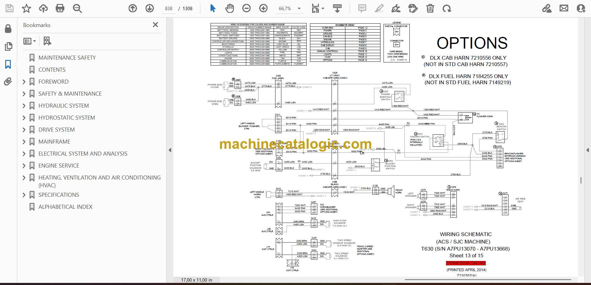
- ELECTRICAL SCHEMATICS
- ELECTRICAL SYSTEM INFORMATION
- Glossary Of Electrical Symbols
- Standard Cab Harness Connectors
- Deluxe Cab Harness Connectors
- Mainframe Harness Connectors
- Description
- Troubleshooting
- Fuse And Relay Location / Identification
- Solenoid Testing
- BATTERY
- Removal And Installation
- Battery Maintenance
- Maintaining Battery Charge Level
- Battery Service During Machine Storage
- Battery Testing
- Battery Charging
- Using A Booster Battery (Jump Starting)
- ALTERNATOR
- Belt Adjustment
- Belt Replacement
- Charging System Inspection
- Alternator Voltage Testing
- Low Voltage Testing
- High Voltage Testing
- Removal And Installation
- Parts Identification
- STARTER
- Testing
- Removal And Installation
- Parts Identification
- INSTRUMENT PANELS
- Left Panel (Early Models)
- Left Panel (Later Models)
- Display Screen
- Right Panel (Standard Key Panel)
- Right Panel (Keyless Start Panel)
- Right Panel (Deluxe Instrumentation Panel)
- Left Switch Panel
- Right Switch Panel
- Left Side Lower Panel
- Right Side Lower Panel
- Left Panel Removal And Installation
- Right Panel (Standard Key Panel) Removal And Installation
- Right Panel (Keyless Start Panel) Removal And Installation
- Right Panel (Deluxe Instrumentation Panel) Removal And Installation
- Key Switch Disassembly And Assembly
- Alarm Disassembly And Assembly
- Left Switch Panel Removal And Installation
- Right Switch Panel Removal And Installation
- LIGHTS
- Front Removal And Installation
- Rear Removal And Installation
- Cab Light Removal And Installation (Early Model)
- Cab Light Removal And Installation (Later Model)
- BOBCAT CONTROLLERS (GATEWAY AND AUXILIARY)
- Description
- Connector Identification
- Removal And Installation
- BOBCAT CONTROLLER (ACS)
- Description
- Connector And Wire Identification
- Removal And Installation
- BOBCAT CONTROLLER (SJC) (DRIVE)
- Description
- Connector Identification
- Removal And Installation
- SPEED SENSORS (SJC)
- Description
- Testing
- Removal And Installation
- DIAGNOSTIC SERVICE CODES
- Viewing Service Codes
- Service Codes List
- BOBCAT INTERLOCK CONTROL SYSTEM (BICS™)
- Description
- Inspecting The BICS™ (Engine STOPPED – Key ON)
- Inspecting Deactivation Of The Auxiliary Hydraulics System (Engine STOPPED – Key ON)
- Inspecting The Seat Bar Sensor (Engine RUNNING)
- Inspecting The Traction Lock (Engine RUNNING)
- Inspecting The Lift Arm Bypass Control
- Inspecting Deactivation Of Lift And Tilt Functions (ACS And SJC)
- Troubleshooting
- SEAT BAR SENSOR
- Description
- Troubleshooting
- Testing
- Removal And Installation
- Bobcat Interlock Control System (BICS™) Circuit Test
- TRACTION LOCK
- Description
- Troubleshooting
- Inspecting
- CONTROL SYSTEM (ACS)
- Description
- Troubleshooting
- Handle Sensor Connector Disassembly And Assembly
- Switch Handle Removal
- Switch Handle Installation
- Actuator Connector Disassembly And Assembly
- Handle Lock Solenoid Removal And Installation
- Handle Lock Solenoid Disassembly And Assembly
- Foot Sensor Removal And Installation
- Foot Sensor Disassembly And Assembly
- Foot Sensor Lock Solenoid Removal And Installation
- ELECTRICAL / HYDRAULIC CONTROLS
- Identification Chart
- Description
- Identification Chart ACD Group 0
- Identification Chart ACD Group 1
- Identification Chart ACD Group 2
- Identification Chart ACD Group 3
- ELECTRICAL / HYDRAULIC CONTROLS (ACS)
- Identification Chart
- Description
- Identification Chart ACD Group 0
- Identification Chart ACD Group 1
- Identification Chart ACD Group 2
- Identification Chart ACD Group 3
- ELECTRICAL / HYDRAULIC CONTROLS (SJC)
- Identification Chart
- Description
- Identification Chart ACD Group 0
- Identification Chart ACD Group 1
- Identification Chart ACD Group 2
- Identification Chart ACD Group 3
- SERVICE PC (LAPTOP COMPUTER)
- Connecting Remote Start Tool
- Connecting Remote Start Tool (Service Tool)
- CALIBRATION
- Description
- Actuator Testing
- Lift And Tilt Calibration (SJC)
- Hydrostatic Pump Calibration (SJC)
- Lift And Tilt Calibration (ACS)
- STEERING DRIFT COMPENSATION (OPERATOR MODE)
- STEERING DRIFT COMPENSATION (SERVICE MODE)
- FLYWHEEL RPM SENSOR
- Description
- Removal And Installation
- CONTROL PANEL SETUP
- Right Panel Setup (Deluxe Instrumentation Panel)
- PASSWORD SETUP (DELUXE INSTRUMENTATION PANEL)
- Password Description
- Changing The Owner Password
- Changing The User Passwords
- Password Lockout Feature
- PASSWORD SETUP (KEYLESS START PANEL)
- Password Description
- Changing The Owner Password
- Password Lockout Feature
- MAINTENANCE CLOCK
- BACK-UP ALARM SYSTEM
- Description
- Inspecting
- Adjusting Switch Position
- Troubleshooting (Standard And ACS)
- Troubleshooting (Joystick)
- Alarm Removal And Installation
- Switch Removal And Installation
- FRONT HORN
- Removal And Installation
- Troubleshooting
- Troubleshooting (Joystick)
- ENGINE SERVICE
- ENGINE INFORMATION
- Description
- Specifications
- Torque Values
- Troubleshooting
- Engine Removal And Installation
- Engine Mount Replacement
- Compression – Testing
- ENGINE SPEED CONTROL
- Removal And Installation
- Disassembly And Assembly
- Cable Removal And Installation
- ENGINE SPEED CONTROL (SJC) (S/N A7PU11001 – A7PU11431)
- Removal And Installation
- Disassembly And Assembly
- ENGINE SPEED CONTROL (SJC) (S/N A7PU11432 & ABOVE)
- Removal And Installation
- Disassembly And Assembly
- MUFFLER
- AIR CLEANER
- Housing Removal And Installation
- Housing Bracket Removal And Installation
- ENGINE COOLING SYSTEM (EARLY MODELS)
- Radiator Removal And Installation
- Hydraulic Fan Description
- Fan Duct Removal And Installation
- Hydraulic Fan Motor Assembly Removal And Installation
- Hydraulic Fan Motor Removal And Installation
- Hydraulic Fan Motor Disassembly And Assembly
- Blower Housing Removal And Installation
- Water Pump Removal And Installation
- Water Pump Disassembly And Assembly
- Thermostat Housing Removal And Installation
- Thermostat – Testing
- ENGINE COOLING SYSTEM (LATER MODELS)
- Radiator / Oil Cooler Removal And Installation
- Hydraulic Fan Description
- Fan Duct Removal And Installation
- Hydraulic Fan Motor Assembly Removal And Installation
- Hydraulic Fan Motor Removal And Installation
- Hydraulic Fan Motor Disassembly And Assembly
- Blower Housing Removal And Installation
- Water Pump Removal And Installation
- Water Pump Disassembly And Assembly
- Thermostat Housing Removal And Installation
- Thermostat – Testing
- LUBRICATION SYSTEM
- Oil Pan Removal And Installation
- Oil Pump Removal And Installation
- Relief Valve – Testing
- Oil Pump Inspection
- Oil Filter Cooler Removal And Installation
- Engine Oil Pressure – Testing
- FUEL SYSTEM
- Fuel Shutoff Solenoid – Testing
- Fuel Shutoff Solenoid Removal And Installation
- Fuel Injection Pump – Testing
- Fuel Injection Pump Assembly Removal And Installation
- Governor Housing Disassembly And Assembly
- Governor Disassembly And Assembly
- Fuel Camshaft Removal And Installation
- Fuel Injection Pump Removal And Installation
- Fuel Injection Pump – Timing
- Fuel Injector Removal And Installation
- Fuel Injector Nozzle Pressure – Testing
- Nozzle Spray Condition
- Valve Seat Tightness
- CYLINDER HEAD
- Glow Plugs – Testing
- Glow Plugs Removal And Installation
- Valve Clearance Adjustment
- Valve Timing – Inspecting
- Cylinder Head Removal And Installation
- Cylinder Head Disassembly And Assembly
- Cylinder Head – Servicing
- Cylinder Head Top Clearance
- Valve Guide – Inspecting
- Valve Guide Removal And Installation
- Reconditioning The Valve And Valve Seat
- Valve Spring
- Valve Tappets
- Rocker Arm And Shaft – Checking
- Bridge Arm And Bridge Arm Shaft – Checking
- Bridge Arm Shaft – Removal And Installation
- Push Rod Alignment – Inspecting
- CRANKSHAFT AND PISTONS
- Piston And Connecting Rod Removal And Installation
- Piston And Connecting Rod – Servicing
- Cylinder Bore – Measuring
- Connecting Rod Alignment
- Crankshaft Gear Removal And Installation
- Crankshaft And Bearings Removal And Installation
- Crankshaft And Bearings – Servicing
- CAMSHAFT AND TIMING GEARS
- Timing Gearcase Cover Removal
- Timing Gearcase Cover Installation
- Timing Gears Backlash – Measuring
- Idler Gear And Camshaft Removal And Installation
- Camshaft – Servicing
- Idler Gear And Shaft – Servicing
- TURBOCHARGER
- Description
- Testing
- Removal And Installation
- FLYWHEEL AND HOUSING
- Flywheel Removal And Installation
- Ring Gear Removal And Installation
- Housing Removal And Installation
- EXHAUST GAS RECIRCULATION (EGR) SYSTEM
- Description
- Testing
- Removal And Installation
- Disassembly And Assembly
- HEATING, VENTILATION AND AIR CONDITIONING (HVAC)
- AIR CONDITIONING SYSTEM FLOW
- Description
- Chart
- Components
- Safety Equipment
- REGULAR MAINTENANCE
- Filters
- Compressor Drive Belt Adjustment
- Compressor Drive Belt Replacement
- Condenser
- Air Conditioning Lubrication
- Air Conditioning Service Chart
- Evaporator / Heater Coil
- TROUBLESHOOTING
- Blower Motor Does Not Operate
- Blower Motor Operates Normally, But Air Flow Is Insufficient
- Insufficient Cooling Although Air Flow And Compressor Operation Are Normal
- The Compressor Does Not Operate At All, Or Operates Improperly
- Gauge Pressure Related Troubleshooting
- Troubleshooting Tree
- Temperature / Pressure Chart
- Poor A/C Performance
- HVAC Repair And Leaks
- Electrical System
- Engine Coolant Bypassing The Heater Valve
- Heater Valve Not Opening Or Closing
- SYSTEM CHARGING AND RECLAMATION
- Refrigerant Identification
- Reclamation And Charging With Recovery / Charging Unit
- COMPRESSOR
- Removal And Installation
- Oil
- Oil Check
- CONDENSER (EARLY MODELS)
- CONDENSER (LATER MODELS)
- RECEIVER / DRIER (EARLY MODELS)
- Receiver / Drier Removal And Installation
- Pressure Relief Valve Removal And Installation
- Pressure Switch Removal And Installation
- Schrader® Valve Removal And Installation
- RECEIVER / DRIER (LATER MODELS)
- Receiver / Drier Removal And Installation
- Pressure Switch Removal And Installation
- Schrader® Valve Removal And Installation
- EVAPORATOR / HEATER UNIT
- Removal And Installation (Early Models)
- Removal And Installation (Later Models)
- THERMOSTAT
- Description
- Removal And Installation (Early Models)
- Removal And Installation (Later Models)
- EXPANSION VALVE
- Removal And Installation (Early Models)
- Removal And Installation (Later Models)
- EVAPORATOR COIL
- Removal And Installation (Early Models)
- Removal And Installation (Later Models)
- HEATER COIL
- Removal And Installation (Early Models)
- Removal And Installation (Later Models)
- BLOWER FAN
- Removal And Installation
- Disassembly And Assembly
- HEATER VALVE
- Removal And Installation (Early Models)
- Removal And Installation (Later Models)
- EVAPORATOR / HEATER COVER
- SPECIFICATIONS
- (T630) LOADER SPECIFICATIONS
- Machine Dimensions
- Performance
- Engine
- Drive System
- Controls
- Hydraulic System
- Electrical System
- Capacities
- Tracks
- Ground Pressure
- TORQUE SPECIFICATIONS FOR BOLTS
- Torque For General SAE Bolts
- Torque For General Metric Bolts
- HYDRAULIC CONNECTION SPECIFICATIONS
- Straight Thread O-ring Fitting
- Flare Fitting
- Tubelines And Hoses
- HYDRAULIC / HYDROSTATIC FLUID SPECIFICATIONS
- CONVERSIONS
- Decimal And Millimeter Equivalent Chart
- U.S. To Metric Conversion Chart
- SERVICE TOOLS REQUIRED
- Remote Start Tools
- Hydraulic Tools
- Mainframe And Drive Tools
- Electrical Tools
- Engine Tools
- HVAC Tools
- ALPHABETICAL INDEX
Bobcat Software
Bobcat PDF Manuals


