The S850 is a big-frame skid-steer that lives on grading crews, demo jobs, snow work, and heavy pallet handling. The service manual is what you grab when the machine is down and you actually have to fix something, not just grease it. Around my shop, I reach for this when I need system specs, test points, or step-by-step tear-down info so I don't guess and turn a 2-hour repair into a 2-day mess.
What this manual helps you do
- Diagnose hydraulic problems by checking test ports, pressures, and valve functions on the S850 loader
- Trace and repair electrical faults using wiring diagrams and connector callouts
- Follow step-by-step procedures to pull and reinstall drive motors, pumps, and major hydraulic components
- Rebuild or replace engine and drivetrain components with the right sequences and torque references
- Adjust and verify controls, linkages, and the Bob-Tach system after repairs so the loader runs straight and safe
Who this is for
If you own or maintain an S850 with serial number in the ATF511001-ATF599999 range, this is the right service manual. It fits small contractors, rental fleets, field techs, and owner-operators who actually turn wrenches. If you just need basic controls, safety, or daily checks, you want the operator's handbook instead, not this.
FAQ
Q: Is this a searchable PDF, and can you read the wiring diagrams clearly?
A: Yes, it's typically a searchable PDF and the wiring diagrams are laid out so you can zoom in and follow circuits.
Q: My S850 serial number is outside ATF511001-ATF599999. Will this work?
A: No, you should match the manual to your exact serial range, since specs and wiring may change.
Q: I'm only doing routine maintenance. Is this overkill?
A: For basic filters and fluids, yes, it's more than you need. For real diagnostics or tear-downs, this is the right document.
Bottom line: If your S850 falls in that ATF511001-ATF599999 serial range and you're doing real repairs, this is the manual you want. If not, keep looking.
📘 Show Index
Table of Contents:
- MAINTENANCE SAFETY
- CONTENTS
- FOREWORD
- FOREWORD
- SAFETY INSTRUCTIONS
- FIRE PREVENTION
- Maintenance
- Operation
- Electrical
- Hydraulic System
- Fueling
- Starting
- Spark Arrester Exhaust System
- Welding And Grinding
- Fire Extinguishers
- SERIAL NUMBER LOCATIONS
- Loader Serial Number
- Engine Serial Number
- DELIVERY REPORT
- LOADER IDENTIFICATION
- SAFETY & MAINTENANCE
- LIFTING AND BLOCKING THE LOADER
- LIFT ARM SUPPORT DEVICE
- Description
- Installing
- Removing
- OPERATOR CAB
- Description
- Raising
- Lowering
- Cab Door Sensor
- Special Applications Kit
- Special Applications Kit Inspection And Maintenance
- Forestry Door And Window Kit
- Forestry Door And Window Kit Inspection And Maintenance
- TRANSPORTING THE LOADER ON A TRAILER
- Loading And Unloading
- Fastening
- TOWING THE LOADER
- REMOTE START TOOL KIT – MEL1563
- Remote Start Tool – MEL1563
- Service Tool Harness Communicator – MEL1566
- Remote Start Procedure
- REMOTE START TOOL (SERVICE TOOL) KIT – 7217666
- Description
- Remote Start Tool (Service Tool) – 7022042
- Loader Service Tool Harness – 6689747
- Computer Service Tool Harness – 6689746
- Remote Start Procedure
- DIAGMASTER (SERVICE TOOL) KIT – 7024161
- Diagmaster (Service Tool)
- DST-i LED Table
- DST-i Operation Status And Display Specification
- Diagmaster (Service Tool) Procedure
- SERVICE SCHEDULE
- ENGINE AIR CLEANER
- Replacing Filter Elements
- ENGINE COOLING SYSTEM
- Maintenance Platform
- Cleaning
- Checking And Adding Coolant
- Removing And Replacing Coolant
- FUEL SYSTEM
- Fuel Specifications
- Biodiesel Blend Fuel
- Filling The Fuel Tank
- Fuel Filter
- Removing Air From The Fuel System
- ENGINE LUBRICATION SYSTEM
- Checking And Adding Engine Oil
- Engine Oil Chart
- Removing And Replacing Oil And Filter
- HYDRAULIC / HYDROSTATIC SYSTEM
- Checking And Adding Fluid
- Hydraulic / Hydrostatic Fluid Chart
- Removing And Replacing Hydraulic Fluid
- Removing And Replacing Hydraulic / Hydrostatic Filter
- Removing And Replacing Hydraulic Charge Filter
- Replacing Reservoir Breather Cap
- FINAL DRIVE TRANSMISSION (CHAINCASE)
- Checking And Adding Fluid
- Removing And Replacing Fluid
- BOB-TACH (HAND LEVER)
- Inspection And Maintenance
- BOB-TACH (POWER)
- Inspection And Maintenance
- LUBRICATING THE LOADER
- TIRE MAINTENANCE
- Wheel Nuts
- Rotating
- Mounting
- PIVOT PINS
- Inspection And Maintenance
- LOADER STORAGE AND RETURN TO SERVICE
- Storage
- Return To Service
- STOPPING THE ENGINE AND LEAVING THE LOADER
- EMERGENCY EXIT
- Rear Window Identification
- Rear Window Removal (Latches)
- Rear Window Removal (Rubber Cord)
- External Access (Rear Window With Latches)
- External Access (Rear Window With Rubber Cord)
- Front Door
- SEAT BELT
- Inspection And Maintenance
- HYDRAULIC SYSTEM
- HYDRAULIC / HYDROSTATIC SCHEMATICS
- HYDRAULIC SYSTEM INFORMATION
- Glossary Of Hydraulic / Hydrostatic Symbols
- Troubleshooting
- CYLINDER (LIFT)
- Testing
- Removal And Installation
- Parts Identification (Earlier Models)
- Parts Identification (Later Models)
- Disassembly
- Assembly
- CYLINDER (TILT)
- Testing
- Removal And Installation
- Base End Pivot Pin Removal And Installation
- Parts Identification (Earlier Models)
- Parts Identification (Later Models)
- Disassembly
- Assembly
- CYLINDER (BOB-TACH)
- Testing
- Removal And Installation
- Parts Identification
- Disassembly
- Assembly
- MAIN RELIEF VALVES
- Description
- Testing
- Main Relief Valve Adjustment
- Main Relief Valve Removal And Installation
- Auxiliary Relief Valve Adjustment
- Auxiliary Relief Valve Removal And Installation
- HYDRAULIC CONTROL VALVE (SJC)
- Description
- Removal And Installation
- Actuator Removal And Installation (In Loader)
- Actuator Removal And Installation (Out Of Loader)
- Identification Chart
- Mount Bracket Removal And Installation
- Lift Load Check Valve Removal And Installation
- Load Check Valve Removal And Installation (Tilt And Auxiliary)
- Anti-Cavitation Valve Removal And Installation (Lift, Rod End)
- Port Relief / Anti-Cavitation Valve Removal And Installation (Lift, Base End)
- Port Relief / Anti-Cavitation Valve Removal And Installation (Tilt, Base End)
- Port Relief / Anti-Cavitation Valve Removal And Installation (Tilt, Rod End)
- Port Relief Valve Removal And Installation
- Plug Removal And Installation
- End Cap Block Removal And Installation
- Lift Spool Removal And Installation
- Lift Spool Disassembly And Assembly
- Tilt Spool Removal And Installation
- Auxiliary Spool Removal And Installation
- Auxiliary Solenoid Removal And Installation
- Solenoid Removal And Installation
- Lock Valve Removal And Installation
- Lift Arm Bypass Orifice Removal And Installation
- Main Relief Valve Removal And Installation
- Auxiliary Relief Valve Removal And Installation
- Check Valve Removal And Installation
- HYDRAULIC CONTROL VALVE (SCPA)
- Description
- Removal And Installation
- Mount Bracket Removal And Installation
- Identification Chart
- Lift Load Check Valve Removal And Installation
- Load Check Valve Removal And Installation (Tilt And Auxiliary)
- Anti-Cavitation Valve Removal And Installation (Lift, Rod End)
- Port Relief / Anti-Cavitation Valve Removal And Installation (Lift, Base End)
- Port Relief / Anti-Cavitation Valve Removal And Installation (Tilt, Base End)
- Port Relief / Anti-Cavitation Valve Removal And Installation (Tilt, Rod End)
- Port Relief Valve Removal And Installation
- Plug Removal And Installation
- Rubber Boot Removal And Installation
- End Cap Block Removal And Installation
- Lift Spool And Detent Removal And Installation
- Tilt Spool Removal And Installation
- Auxiliary Spool Removal And Installation
- Auxiliary Solenoid Removal And Installation
- Solenoid Removal And Installation
- Lock Valve Removal And Installation
- Lift Arm Bypass Orifice Removal And Installation
- Main Relief Valve Removal And Installation
- Auxiliary Relief Valve Removal And Installation
- Check Valve Removal And Installation
- LIFT ARM BYPASS CONTROL VALVE
- Description
- Testing
- Removal And Installation
- Bracket Removal And Installation
- Disassembly And Assembly
- HYDRAULIC PUMP
- Description
- Pump Test At Quick Couplers
- Direct Pump Test (Standard Section)
- Direct Pump Test (Charge Section)
- Removal And Installation
- Hydraulic Pump Startup
- Parts Identification
- Disassembly And Assembly
- HYDRAULIC PUMP (HIGH FLOW)
- Description
- Pump Test At Quick Couplers
- Direct Pump Test (Standard Section)
- Direct Pump Test (Charge Section)
- Direct Pump Test (High Flow Section)
- High Flow Relief Valve Adjustment
- High Flow Relief Valve Removal And Installation
- Solenoid Removal And Installation
- Removal And Installation
- Hydraulic Pump Startup
- Parts Identification
- Disassembly And Assembly
- HYDRAULIC / HYDROSTATIC FILTERS
- Description
- Housing Removal And Installation
- HYDRAULIC FLUID RESERVOIR
- Description
- Removal And Installation
- Hydraulic Fluid Screen
- OIL COOLER
- Description
- Removal And Installation
- BUCKET POSITION VALVE
- Description
- Solenoid Removal And Installation
- Solenoid Testing
- Removal And Installation
- Disassembly And Assembly
- REAR AUXILIARY DIVERTER VALVE
- Description
- Solenoid Testing
- Removal And Installation
- Disassembly And Assembly
- BOB-TACH (POWER) BLOCK (EARLIER MODELS)
- Description
- Removal And Installation
- Disassembly And Assembly
- BOB-TACH (POWER) BLOCK (LATER MODELS)
- Description
- Testing Relief Valve
- Removal And Installation
- Disassembly And Assembly
- FRONT AUXILIARY HYDRAULIC COUPLER BLOCK
- Description
- Removal And Installation
- Disassembly And Assembly (FFI/FI)
- Disassembly And Assembly (FFH/FH)
- HYDROSTATIC SYSTEM
- HYDROSTATIC SYSTEM INFORMATION
- Description
- Troubleshooting
- HYDROSTATIC MOTOR (TWO-SPEED) (S/N ATF411001 – ATF411599)
- Description
- Removal And Installation
- Parts Identification
- Disassembly
- Assembly
- HYDROSTATIC MOTOR (TWO-SPEED) (S/N ATF411600 & ABOVE AND S/N ATF511001 & ABOVE)
- Description
- Removal And Installation
- Parts Identification
- Disassembly
- Assembly
- HYDROSTATIC MOTOR CARRIER (SJC AND SCPA)
- Description
- Removal And Installation
- Parts Identification
- Disassembly
- Assembly
- CHARGE PRESSURE
- Description
- Testing
- Sender Removal And Installation
- Adjusting
- HYDROSTATIC PUMP (SJC AND SCPA)
- Description
- Hydraulic Controller Removal And Installation
- Removal And Installation
- Hydrostatic Pump Startup
- Parts Identification
- High Pressure Relief And Bypass Valve
- Charge Relief Valve
- Disassembly
- Inspection
- Assembly
- Mechanical Neutral Adjustment
- Hydraulic Controller Neutral Adjustment
- DRIVE BELT
- Belt Adjustment
- Stop Adjustment
- Belt Replacement
- Tensioner Pulley Removal And Installation
- Tensioner Pulley Disassembly And Assembly
- TWO-SPEED / BRAKE VALVE (S/N ATF411001 – ATF411599)
- Description
- Valve Block Removal And Installation
- Valve Block Disassembly And Assembly
- TWO-SPEED / BRAKE VALVE (S/N ATF411600 & ABOVE AND S/N ATF511001 & ABOVE)
- Description
- Valve Block Removal And Installation
- Valve Block Disassembly And Assembly
- DRAIN MANIFOLD
- Description
- Drain Manifold Removal And Installation
- DRIVE SYSTEM
- BRAKE (TWO-SPEED)
- DRIVE COMPONENTS
- Description
- Axle Seal Removal And Installation
- Axle, Sprocket And Bearings Removal And Installation
- Chain Removal And Installation
- CHAINCASE
- Description
- Front Cover Removal And Installation
- Center Cover Removal And Installation
- Rear Cover Removal And Installation
- MAINFRAME
- SEAT BAR
- Description
- Removal And Installation
- Disassembly And Assembly
- Compression Spring Disassembly And Assembly
- OPERATOR CAB
- Gas Spring Removal And Installation
- Gas Spring Bracket Disassembly And Assembly
- Removal And Installation
- OPERATOR SEAT (SUSPENSION)
- Removal And Installation
- Slide Rail Removal And Installation
- Seat Belt Removal And Installation
- Lower Cushion Removal
- Lower Cushion Installation
- Back Cushion Removal And Installation
- Shock Removal And Installation
- 3-Point Seat Belt Removal And Installation
- BOB-TACH (HAND LEVER)
- Description
- Removal And Installation
- Lever And Wedge Disassembly And Assembly
- Pivot Pin Bushing And Seal Removal And Installation
- BOB-TACH (POWER)
- Description
- Removal And Installation
- Lever And Wedge Disassembly And Assembly
- Pivot Pin Bushing And Seal Removal And Installation
- LIFT ARMS
- Stabilizer Bar Removal And Installation
- Link Removal And Installation
- Removal And Installation
- REAR GRILLE
- Removing
- Installing
- Shield Removal And Installation
- REAR DOOR (TAILGATE)
- Removal And Installation
- Striker Removal And Installation
- Striker Disassembly And Assembly
- Striker (Adjusting)
- Latch Removal And Installation (Earlier Models)
- Latch Removal And Installation (Later Models)
- FUEL TANK
- Removal And Installation
- Fuel Level Sender Removal And Installation
- Fuel Fill Screen Removal And Installation
- FUEL TANK (AUXILIARY)
- CONTROL PEDALS AND LINKAGES (SCPA)
- Description
- Pedal Removal And Installation
- Linkage Removal And Installation
- Pedal (Adjusting)
- Floor Pan Removal And Installation
- CONTROL PANEL (SJC)
- Description
- Removal And Installation
- CONTROL PANEL (SCPA)
- Description
- Removal And Installation
- CONTROL HANDLE / LEVER (SJC)
- Description
- Joystick Testing
- Joystick Removal And Installation
- CONTROL HANDLE / LEVER (SCPA)
- Description
- Steering Handle Testing
- Steering Handle Removal And Installation
- ACCESS PANEL (INSIDE) (SJC)
- Removal And Installation (Left)
- Removal And Installation (Right)
- ACCESS PANEL (INSIDE) (SCPA)
- Removal And Installation (Left)
- Removal And Installation (Right)
- WINDOW (REAR)
- Rear Window Identification
- Removal (Rubber Cord)
- Installation (Rubber Cord)
- Removal And Installation (Latches)
- Disassembly And Assembly (Latches)
- WINDOW (TOP)
- WINDOW (SIDE)
- CAB DOOR
- Description
- Removal And Installation
- Disassembly And Assembly
- Aligning
- Adjusting
- Checking Operation
- ARMREST
- Description
- Removal And Installation
- Disassembly And Assembly
- LEFT SIDE LOWER PANEL
- Removal And Installation
- Disassembly And Assembly
- RIGHT SIDE LOWER PANEL
- Removal And Installation
- Disassembly And Assembly
- HEADLINER
- ELECTRICAL SYSTEM AND ANALYSIS
- ELECTRICAL SCHEMATICS
- ELECTRICAL SYSTEM INFORMATION
- Glossary Of Electrical Symbols
- Deluxe Cab Harness Connectors (Earlier Models)
- Deluxe Cab Harness Connectors (Later Models)
- Mainframe Harness Connectors
- Engine Harness Connectors
- Description
- Troubleshooting
- Fuse And Relay Location / Identification
- Solenoid Testing
- BATTERY
- Removal And Installation
- Servicing
- Using A Booster Battery (Jump Starting)
- ALTERNATOR
- Belt Adjustment
- Belt Replacement
- Charging System Inspection
- Alternator Voltage Testing
- Low Voltage Testing
- High Voltage Testing
- Removal And Installation
- Parts Identification
- STARTER
- Testing
- Removal And Installation
- Parts Identification
- INSTRUMENT PANELS
- Left Panel
- Display Screen
- Right Panel (Standard Key Panel)
- Right Panel (Keyless Start Panel)
- Right Panel (Deluxe Instrumentation Panel)
- Left Switch Panel
- Right Switch Panel
- Left Side Lower Panel
- Right Side Lower Panel
- Left Panel Removal And Installation
- Right Panel Removal And Installation
- Key Switch Disassembly And Assembly
- Alarm Disassembly And Assembly
- Left Switch Panel Removal And Installation
- Right Switch Panel Removal And Installation
- LIGHTS
- Front Removal And Installation
- Rear Removal And Installation
- Cab Light Removal And Installation (Earlier Models)
- Cab Light Removal And Installation (Later Models)
- BOBCAT CONTROLLERS (GATEWAY AND AUXILIARY)
- Description
- Connector Identification
- Removal And Installation
- BOBCAT CONTROLLER (ACS)
- Description
- Connector And Wire Identification
- Removal And Installation
- BOBCAT CONTROLLER (SJC) (DRIVE)
- Description
- Connector Identification
- Removal And Installation
- BOBCAT CONTROLLER (SCPA) (DRIVE)
- Description
- Connector Identification
- Removal And Installation
- ENGINE CONTROL UNIT (ECU)
- Description
- Cleaning
- Removal And Installation
- ECU Replacement
- DIAGNOSTIC SERVICE CODES
- Viewing Service Codes
- Service Codes List
- DIAGMASTER DIAGNOSTIC TROUBLE CODES (DTC)
- BOBCAT INTERLOCK CONTROL SYSTEM (BICS™)
- Description
- Inspecting The BICS™ (Engine STOPPED – Key ON)
- Inspecting Deactivation Of The Auxiliary Hydraulics System (Engine STOPPED – Key ON)
- Inspecting The Seat Bar Sensor (Engine RUNNING)
- Inspecting The Traction Lock (Engine RUNNING)
- Inspecting The Lift Arm Bypass Control
- Inspecting Deactivation Of Lift And Tilt Functions (SJC)
- Troubleshooting
- SEAT BAR SENSOR
- Description
- Troubleshooting
- Testing
- Removal And Installation
- Bobcat Interlock Control System (BICS™) Circuit Test
- TRACTION LOCK
- Description
- Troubleshooting
- Inspecting
- ELECTRICAL / HYDRAULIC CONTROLS (SJC)
- Identification Chart
- Description
- Identification Chart ACD Group 0
- Identification Chart ACD Group 1
- Identification Chart ACD Group 2
- Identification Chart ACD Group 3
- ELECTRICAL / HYDRAULIC CONTROLS (SCPA)
- Identification Chart
- Description
- Identification Chart ACD Group 0
- Identification Chart ACD Group 1
- Identification Chart ACD Group 2
- Identification Chart ACD Group 3
- SERVICE PC (LAPTOP COMPUTER)
- Connecting Remote Start Tool
- Connecting Remote Start Tool (Service Tool)
- Connecting Diagmaster (Service Tool)
- Connecting Remote Parked Regeneration Kit
- CALIBRATION
- Description
- Actuator Testing
- Lift And Tilt Calibration (SJC)
- Hydrostatic Pump Calibration (SJC)
- Hydrostatic Pump Calibration (SCPA)
- STEERING DRIFT COMPENSATION (OPERATOR MODE)
- STEERING DRIFT COMPENSATION (SERVICE MODE)
- CONTROL PANEL SETUP
- Right Panel Setup (Deluxe Instrumentation Panel)
- PASSWORD SETUP (DELUXE INSTRUMENTATION PANEL)
- Password Description
- Changing The Owner Password
- Changing The User Passwords
- Password Lockout Feature
- PASSWORD SETUP (KEYLESS START PANEL)
- Password Description
- Changing The Owner Password
- Password Lockout Feature
- MAINTENANCE CLOCK
- BACK-UP ALARM SYSTEM
- Description
- Inspecting
- Troubleshooting (Joystick)
- Alarm Removal And Installation
- FRONT HORN
- Removal And Installation
- Troubleshooting
- Troubleshooting (Joystick)
- ENGINE SERVICE
- ENGINE INFORMATION
- Description
- Specifications
- Sensor Location
- Torque Values
- Troubleshooting
- Engine Removal And Installation
- Engine Mount Replacement
- Compression – Testing
- Injector Signal – Testing
- ENGINE SPEED CONTROL (HAND)
- ENGINE SPEED CONTROL (FOOT)
- Removal And Installation
- Disassembly And Assembly
- Foot Throttle Calibration
- DIESEL PARTICULATE FILTER (DPF) SYSTEM
- Description
- Removal And Installation
- DPF Regeneration
- DPF Regeneration Table
- Operation (Standard Switch)
- Operation (Optional Inhibit Switch Kit)
- Operation (Optional Remote Parked Regeneration Kit)
- Remote Parked Regeneration (Level 3)
- DPF Service Regeneration (Level 4)
- DPF Cleaning (Level 5)
- AIR CLEANER
- Housing Removal And Installation
- ENGINE COOLING SYSTEM
- Radiator Removal And Installation
- Hydraulic Fan Description
- Lower Fan Duct Removal And Installation
- Hydraulic Fan Motor Assembly Removal And Installation (Earlier Models)
- Fan Removal And Installation (Earlier Models)
- Hydraulic Fan Motor Removal And Installation (Earlier Models)
- Hydraulic Fan Disassembly And Assembly (Earlier Models)
- Hydraulic Fan Motor Assembly Removal And Installation (Later Models)
- Fan Removal And Installation (Later Models)
- Hydraulic Fan Motor Removal And Installation (Later Models)
- Hydraulic Fan Disassembly And Assembly (Later Models)
- Blower Housing Removal And Installation
- Water Pump Removal And Installation
- Water Pump Disassembly And Assembly
- Thermostat Housing Removal And Installation
- Thermostat – Checking
- LUBRICATION SYSTEM
- Oil Pan Removal And Installation
- Oil Pump Removal And Installation
- Oil Pump Inspection
- Oil Filter Cooler Removal And Installation
- Engine Oil Pressure – Testing
- Crankcase Ventilation Filter Removal And Installation
- FUEL SYSTEM
- Supply Pump Removal
- Supply Pump Installation
- Supply Pump Difference Learning
- Fuel Cooler Bypass Valve Removal And Installation
- Fuel Recirculation Valve Removal And Installation
- Fuel Rail Assembly Removal And Installation
- Supply Pump – Timing
- Fuel Injector Removal And Installation
- Injector Correction
- Removing Air From The Fuel System
- CYLINDER HEAD
- Intake Air Heater – Testing
- Intake Air Heater Removal And Installation
- Valve Clearance Adjustment
- Valve Timing – Checking
- Cylinder Head Removal And Installation
- Cylinder Head Disassembly And Assembly
- Cylinder Head – Servicing
- Cylinder Head Top Clearance
- Valve Guide – Inspecting
- Reconditioning The Valve And Valve Seat
- Valve Spring
- Valve Tappets
- Rocker Arm And Shaft – Inspecting
- Valve Bridge Arm And Shaft – Inspecting
- Push Rod Alignment – Inspecting
- CRANKSHAFT AND PISTONS
- Piston And Connecting Rod Removal And Installation
- Piston And Connecting Rod – Servicing
- Cylinder Bore – Testing
- Connecting Rod Alignment
- Crankshaft Gear Removal And Installation
- Crankshaft And Bearings Removal
- Crankshaft And Bearings Installation
- Crankshaft And Bearings – Servicing
- CRANKSHAFT POSITION SENSOR
- Description
- Removal And Installation
- Adjusting
- CAMSHAFT AND TIMING GEARS
- Timing Gearcase Cover Removal And Installation
- Timing Gears Backlash – Testing
- Idler Gear And Camshaft Removal And Installation
- Camshaft – Servicing
- Idler Gear And Shaft – Servicing
- TURBOCHARGER
- Description
- Removal And Installation
- Testing
- EGR Cooler Testing
- FLYWHEEL AND HOUSING
- Flywheel Removal And Installation
- Ring Gear Removal And Installation
- Housing Removal And Installation
- EXHAUST GAS RECIRCULATION (EGR) SYSTEM
- Description
- Testing
- Removal And Installation
- HEATING, VENTILATION AND AIR CONDITIONING (HVAC)
- AIR CONDITIONING SYSTEM FLOW
- Description
- AC System Diagram
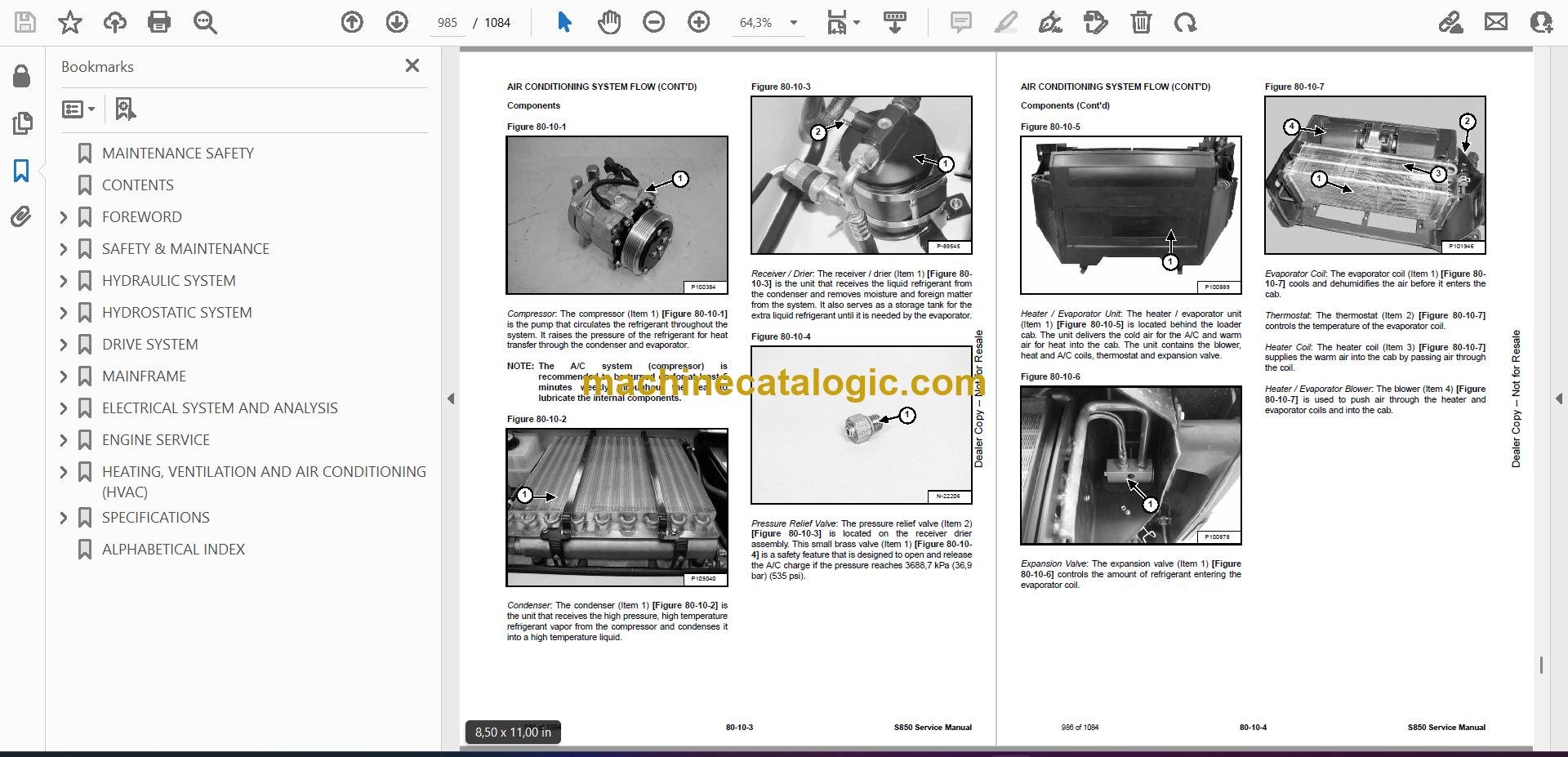
- Components
- Safety Equipment
- REGULAR MAINTENANCE
- Filters
- Compressor Drive Belt Adjustment
- Compressor Drive Belt Replacement
- Condenser
- Air Conditioning Lubrication
- Air Conditioning Service Chart
- Evaporator / Heater Coil
- TROUBLESHOOTING
- Blower Motor Does Not Operate
- Blower Motor Operates Normally, But Air Flow Is Insufficient
- Insufficient Cooling Although Air Flow And Compressor Operation Are Normal
- The Compressor Does Not Operate At All, Or Operates Improperly
- The Compressor Does Not Operate At All, Or Operates Improperly (Cont’d)
- Gauge Pressure Related Troubleshooting
- Troubleshooting Tree
- Temperature / Pressure Chart
- Poor A/C Performance
- HVAC Repair And Leaks
- Electrical System
- Engine Coolant Bypassing The Heater Valve
- Heater Valve Not Opening Or Closing
- SYSTEM CHARGING AND RECLAMATION
- Refrigerant Identification
- Reclamation And Charging With Recovery / Charging Unit
- COMPRESSOR
- Removal And Installation
- Oil
- Oil Check
- CONDENSER
- RECEIVER / DRIER (EARLIER MODELS)
- Receiver / Drier Removal And Installation
- Pressure Relief Valve Removal And Installation
- Pressure Switch Removal And Installation
- Schrader® Valve Removal And Installation
- RECEIVER / DRIER (LATER MODELS)
- Receiver / Drier Removal And Installation
- Pressure Switch Removal And Installation
- Schrader® Valve Removal And Installation
- EVAPORATOR / HEATER UNIT
- THERMOSTAT
- Description
- Removal And Installation
- EXPANSION VALVE
- EVAPORATOR COIL
- HEATER COIL
- BLOWER FAN
- Removal And Installation
- Disassembly And Assembly
- HEATER VALVE
- EVAPORATOR / HEATER COVER
- SPECIFICATIONS
- (S850) LOADER SPECIFICATIONS
- Machine Dimensions
- Performance
- Engine
- Drive System
- Controls
- Hydraulic System
- Electrical System
- Capacities
- Tires
- TECHNICAL SERVICE GUIDE SPECIFICATIONS
- Engine
- Engine Torques
- Cooling System
- Loader Torques
- Hydraulic / Hydrostatic System
- Fuel Consumption
- TORQUE SPECIFICATIONS FOR BOLTS
- Torque For General SAE Bolts
- Torque For General Metric Bolts
- HYDRAULIC CONNECTION SPECIFICATIONS
- Straight Thread O-ring Fitting
- Flare Fitting
- Tubelines And Hoses
- HYDRAULIC / HYDROSTATIC FLUID SPECIFICATIONS
- CONVERSIONS
- Decimal And Millimeter Equivalent Chart
- U.S. To Metric Conversion Chart
- SERVICE TOOLS REQUIRED
- Remote Start Tools
- Hydraulic Tools
- Mainframe And Drive Tools
- Electrical Tools
- Engine Tools
- HVAC Tools
- ALPHABETICAL INDEX
Bobcat Software
Bobcat PDF Manuals


