$ 0
0
$ 0
0

Bobcat TL3870 VersaHANDLER® TTC, Telescopic Handler Service Manual (SN AVKJ14000-AVKJ14999)

Format: PDF (Printable Document)

File Language: English

File Pages: 775

File Size: 25.16 MB (Speed Download Link)

Brand: Bobcat

Model: TL3870 VersaHANDLER® TTC, Telescopic Handler

Book No: 7283170

Serial No: SN AVKJ14000-AVKJ14999

Type of Document: Service Manual

Categories: ,

$ 45

Share:

Bobcat TL3870 VersaHANDLER® TTC, Telescopic Handler Service Manual (SN AVKJ14000-AVKJ14999)

This TL3870 VersaHANDLER is the kind of machine you use for stacking bales, loading manure, feeding, and handling pallets where a skid steer just can't reach. The service manual is what you pull out when something quits lifting right, the boom creeps down, or you're chasing an electrical gremlin on a Sunday afternoon. It's written for people who actually turn wrenches and need to know how things come apart and go back together without guessing.

What this manual helps you do

  • Diagnose hydraulic issues in the boom and stabilizers, and trace weak lift or drift-down problems
  • Check and set pressures in the hydraulic and hydrostatic systems using test ports and gauges
  • Follow step-by-step teardown and reassembly of cylinders, valves, axles, and major drivetrain parts
  • Troubleshoot electrical problems with wiring diagrams, connector locations, and test procedures
  • Replace and adjust wear parts like brakes, steering components, and attachment coupler parts with the right sequences

Who this is for

This manual is for TL3870 VersaHANDLER TTC owners and techs working on machines in the serial range AVKJ14000 through AVKJ14999. If you just want to learn how to drive it or see what button does what, you want the operator's handbook instead, not this shop manual.

FAQ

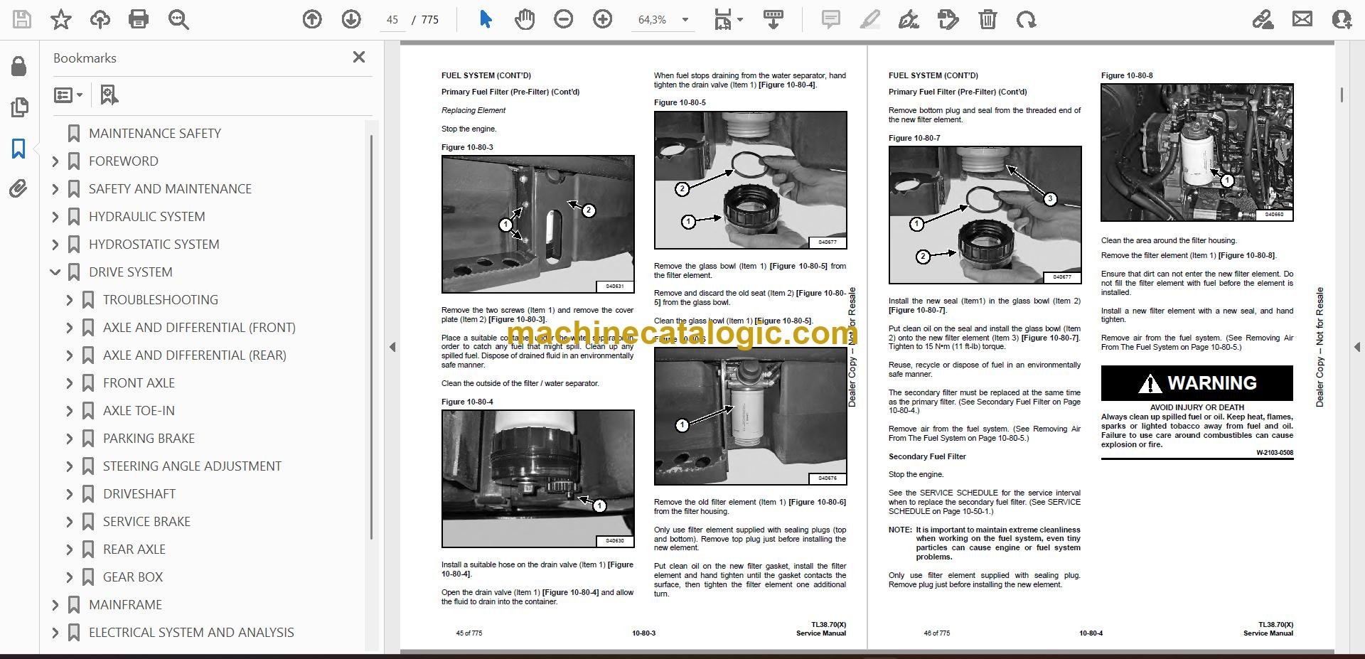
Q: Is this a searchable PDF and can I read the wiring diagrams?

A: Yes, these manuals are usually searchable PDFs, and the wiring diagrams are meant to be zoomed in so you can read wire colors and pin numbers.

Q: How do I know it fits my machine?

A: Check your serial plate. If your TL3870 serial number falls between AVKJ14000 and AVKJ14999, this is the right service manual series.

Q: Is this what I need for real repairs, or is it just basic maintenance?

A: This is the workshop-level service manual, meant for full repairs and diagnostics, not just daily checks and grease points.

Bottom line, if you own or service a TL3870 in that serial range and you're doing your own repairs, this is the yes you're looking for. If your serial number is outside that band, then it's a no.

📘 Show Index

Table of Contents:

  • MAINTENANCE SAFETY
  • FOREWORD
    • FOREWORD
    • SAFETY INSTRUCTIONS
      • Safe Operation Is The Operator’s Responsibility
      • Safe Operation Needs A Qualified Operator
      • Avoid Silica Dust
      • Dismantling And Disposal
    • FIRE PREVENTION
      • Maintenance
      • Operation
      • Electrical
      • Hydraulic System
      • Fueling
      • Starting
      • Welding And Grinding
      • Fire Extinguishers
    • SERIAL NUMBER LOCATION
      • Telescopic Handler Serial Number
      • Telescopic Handler Statutory Plate
      • Engine Serial Number
      • Other Serial Numbers
    • DELIVERY REPORT
    • BOBCAT TELESCOPIC HANDLER IDENTIFICATION
  • SAFETY AND MAINTENANCE
    • LIFTING AND BLOCKING THE TELESCOPIC HANDLER
      • Procedure
    • OPERATOR CAB
      • Description
      • Cab Door
      • Cab Door Window
      • Rear Cab Window
      • Cab Light
    • TRANSPORTING THE TELESCOPIC HANDLER ON A TRAILER
      • Loading And Unloading
      • Fastening
    • TOWING THE TELESCOPIC HANDLER
      • Procedure
    • SERVICE SCHEDULE
      • Maintenance Intervals
    • AIR CLEANER SERVICE
      • Replacing Filter Elements
    • ENGINE COOLING SYSTEM
      • Cleaning
      • Checking Level
      • Removing And Replacing The Coolant
    • FUEL SYSTEM
      • Fuel Specifications
      • Biodiesel Blend Fuel
      • Filling The Fuel Tank
      • Primary Fuel Filter (Pre-Filter)
      • Secondary Fuel Filter
      • Removing Air From The Fuel System
    • ENGINE LUBRICATION SYSTEM
      • Checking And Adding Engine Oil
      • Engine Oil Chart
      • Removing And Replacing Oil And Filter
    • HYDRAULIC / HYDROSTATIC SYSTEM
      • Checking And Adding Fluid
      • Hydraulic / Hydrostatic Fluid
      • Removing And Replacing Hydraulic Fluid
      • Removing And Replacing Hydraulic / Hydrostatic Filters
      • Removing And Replacing Hydraulic Charge Filter
      • Fill / Breather Cap
      • Hydraulic Fluid Air Bleeding Procedure
      • Starter Procedure (Only For TL35.70(X) And TL38.70(X))
    • AXLES (FRONT AND REAR)
      • Checking And Adding Oil (Planetary Carrier)
      • Removing And Replacing Oil (Planetary Carrier)
      • Checking And Adding Oil (Rear Differential)
      • Removing And Replacing Oil (Rear Differential)
      • Checking And Adding Oil (Front Differential)
      • Removing And Replacing Oil (Front Differential)
      • Checking And Adding Oil (Gear Box)
      • Removing And Replacing Oil (Gear Box)
    • LUBRICATING THE TELESCOPIC HANDLER
      • Lubrication Locations
    • ATTACHMENT CARRIER
      • Inspection And Maintenance
    • TIRE MAINTENANCE
      • Wheel Nuts
      • Rotating
      • Mounting
      • Pressure
    • APPROVED BOOM STOP
      • Installing The Approved Boom Stop
      • Removing The Approved Boom Stop
    • ENGINE COVER
      • Opening And Closing
    • STOPPING THE ENGINE AND LEAVING THE TELESCOPIC HANDLER
      • Procedure
    • EMERGENCY EXIT
      • Rear Window
    • TELESCOPIC HANDLER STORAGE AND RETURN TO SERVICE
      • Storage
      • Return To Service
    • LIFTING THE TELESCOPIC HANDLER
      • Procedure
    • REMOTE START TOOL (SERVICE TOOL) KIT – MEL1563
      • Remote Start Tool – MEL1563
      • Service Tool Harness Control – MEL1565
      • Service Tool Harness Communicator – MEL1566
    • REMOTE START TOOL (SERVICE TOOL) KIT – 7003031
      • Remote Start Tool (Service Tool) – 7003030
      • Telescopic Handler Service Tool Harness – 6689747
      • Computer Service Tool Harness – 6689746
      • Remote Start Procedure
  • HYDRAULIC SYSTEM
    • HYDRAULIC / HYDROSTATIC SCHEMATICS
    • HYDRAULIC SYSTEM INFORMATION
      • Glossary Of Hydraulic / Hydrostatic Symbols
      • Troubleshooting Chart
      • Tightening Procedures
    • LIFT CYLINDER
      • Removal And Installation
      • Parts Identification
      • Disassembly
      • Assembly
    • SELF LEVELING CYLINDER
      • Removal And Installation
      • Parts Identification
      • Disassembly
      • Assembly
    • SELF LEVELING CYLINDER (LOCK VALVE)
      • Removal And Installation
    • EXTENSION CYLINDER
      • Cylinder Group Removal And Installation
      • Upper Tubeline Removal And Installation
      • Extension Cylinder Removal And Installation
      • Tubeline Tray Disassembly
      • Parts Identification
      • Disassembly
      • Assembly
    • TILT CYLINDER
      • Removal And Installation
      • Parts Identification
      • Disassembly
      • Assembly
    • STEERING CYLINDER (FRONT / REAR)
      • Removal
      • Installation
      • Disassembly
      • Assembly
    • GEAR CONTROL CYLINDER
      • Removal
      • Parts Identification
      • Disassembly
      • Assembly
      • Installation
    • MANIFOLD
      • Removal And Installation
      • Parts Identification
      • Disassembly And Assembly
    • BRAKE VALVE
      • Removal And Installation
    • PISTON PUMP
      • Removal And Installation
      • Parts Identification
      • Disassembly And Assembly
    • FAN MOTOR
      • Removal And Installation
      • Parts Identification (Single Speed Version) (Standard)
      • Disassembly And Assembly (Single Speed Version) (Standard)
      • Parts Identification (Variable Speed Version) (Optional)
      • Disassembly And Assembly (Variable Speed Version) (Optional)
    • HYDRAULIC FLUID RESERVOIR
      • Removal And Installation
    • STEERING VALVE
      • Removal And Installation
    • HYDRAULIC CONTROL VALVE
      • Troubleshooting Chart (Controllers)
      • Valve Section Troubleshooting
      • Troubleshooting Chart (Control Valve)
      • Main Relief Valve Removal And Installation
      • Piston Pump Testing
      • Cycle Times @ Full Idle
      • Troubleshooting Chart (Piston Pump Testing)
      • Removal And Installation
      • Parts Identification
      • Disassembly And Assembly
      • End Housing Disassembly And Assembly
      • Auxiliary Valve Section Disassembly And Assembly
      • Telescoping Valve Section Disassembly And Assembly
      • Tilting Valve Section Disassembly And Assembly
      • Lifting Valve Section Disassembly And Assembly
      • Inlet-Outlet Valve Section Disassembly And Assembly
    • PORT RELIEF VALVES
      • Testing
      • Replacement Procedure
    • ACCUMULATORS
      • Brake Accumulator Removal And Installation (If Equipped)
      • Gear Pump Accumulator Removal And Installation
    • FAN PUMP
      • Removal And Installation
      • Disassembly And Assembly
  • HYDROSTATIC SYSTEM
    • HYDROSTATIC SYSTEM INFORMATION
      • Troubleshooting Chart
      • Replenishing Valve Function
    • OIL COOLER
      • Description
    • HYDROSTATIC DRIVE MOTOR
      • Removal And Installation
      • Parts Identification
      • Disassembly
      • Inspection
      • Assembly
    • HYDROSTATIC PUMP
      • Calibration
      • Swash Plate Calibration – Neutral Range
      • Swash Plate Calibration – Maximum Range
      • Removal And Installation
      • Parts Identification
      • Shaft Disassembly
      • Relief Valves Disassembly And Assembly
      • Charge Pump Disassembly
      • Piston Pump Disassembly
      • Solenoid Block Disassembly
      • Inspection
      • Piston Pump Assembly
      • Charge Pump Assembly
      • Solenoid Block Assembly
      • Shaft Assembly
  • DRIVE SYSTEM
    • TROUBLESHOOTING
      • Chart
    • AXLE AND DIFFERENTIAL (FRONT)
      • Description
      • Planetary Carrier Parts Identification
      • Planetary Carrier Disassembly
      • Steering Knuckle And Drive Axle Parts Identification
      • Steering Knuckle Disassembly
      • Drive Axle Disassembly
      • Brake Group Parts Identification
      • Brake Group Disassembly
      • Differential Parts Identification
      • Differential Disassembly
      • Pinion Group Parts Identification
      • Pinion Group Disassembly
      • Pinion Group Assembly
      • Differential Assembly
      • Brake Group Assembly
      • Drive Axle Assembly
      • Steering Knuckle Assembly
      • Planetary Carrier Assembly
      • Special Tools
    • AXLE AND DIFFERENTIAL (REAR)
      • Description
      • Planetary Carrier Parts Identification
      • Planetary Carrier Disassembly
      • Steering Knuckle And Drive Axle Parts Identification
      • Steering Knuckle Disassembly
      • Differential Parts Identification
      • Differential Disassembly
      • Pinion Group Parts Identification
      • Pinion Group Disassembly
      • Pinion Group Assembly
      • Differential Assembly
      • Steering Knuckle Assembly
      • Planetary Carrier Assembly
      • Special Tools
    • FRONT AXLE
      • Removal And Installation
    • AXLE TOE-IN
      • Adjustment
    • PARKING BRAKE
      • Releasing The Brake For Towing
      • Adjustment
      • Brake Cylinder Removal
      • Brake Cylinder Disassembly And Assembly
      • Brake Disc Removal And Installation
      • Brake Cylinder Installation
    • STEERING ANGLE ADJUSTMENT
      • Adjustment
    • DRIVESHAFT
      • Rear Driveshaft Removal And Installation
      • Front Driveshaft Removal And Installation
    • SERVICE BRAKE
      • Description
      • Bleeding The Brake Circuit
    • REAR AXLE
      • Removal And Installation
    • GEAR BOX
      • Removal And Installation
      • Parts Identification
      • Disassembly
      • Assembly
  • MAINFRAME
    • OPERATOR CAB
      • Removal And Installation
    • OPERATOR SEAT
      • Removal And Installation
    • FIXED BOOM
      • Removal
      • Installation
    • INNER BOOM
      • Removal And Installation
    • WEAR PADS (FRONT)
      • Removal And Installation
    • WEAR PADS (REAR)
      • Removal And Installation
    • ENGINE COVER
      • Gas Cylinder Removal And Installation
      • Removal And Installation
    • FUEL TANK
      • Removal And Installation
    • ATTACHMENT CARRIER (QUICK-TACH)
      • Removal And Installation
    • COUNTERWEIGHT
      • Removal And Installation
    • FENDER
      • Removal And Installation
    • STEERING COLUMN COVER
      • Removal And Installation
    • DASH COVER
      • Removal And Installation
    • JOYSTICK PANEL
      • Removal And Installation
  • ELECTRICAL SYSTEM AND ANALYSIS
    • ELECTRICAL SCHEMATICS
    • ELECTRICAL SYSTEM INFORMATION
      • Troubleshooting Chart
      • Description
      • Fuses And Relay Location / Identification
    • BATTERY
      • Battery Maintenance
      • Using A Booster Battery (Jump Starting)
      • Removing And Installing Battery
    • ALTERNATOR
      • Removal And Installation
      • Belt Adjustment
      • Belt Checking
      • Belt Replacement
    • STARTER
      • Testing
      • Removal And Installation
    • LIGHTS
      • Rear Light Removal And Installation
      • Rear Light Bulb Replacement
      • Front Light Removal And Installation
      • Front Light Bulb Replacement
    • SIGNAL LEVER
      • Removal And Installation
    • DISPLAY
      • Removal And Installation
    • INSTRUMENT PANELS
      • Right Instrument And Indicator Panel Removal And Installation
      • Left Instrument Panel Removal And Installation
    • BOOM ANGLE SENSOR
      • Removal And Installation
      • Calibration
    • FRONT WIPER MOTOR
      • Removal And Installation
    • TOP WIPER MOTOR
      • Removal And Installation
    • REAR WIPER MOTOR
      • Removal And Installation
    • PEDAL ASSEMBLY
      • Removal And Installation
    • INCHING SENSOR
      • Removal And Installation
      • Calibration
    • SERVICE PC (LAPTOP COMPUTER)
      • Connecting Remote Start Tool (Service Tool) – MEL1563
      • Connecting Remote Start Tool (Service Tool) – 7003030
    • FUEL LEVEL SENDER
      • Removal And Installation
    • JOYSTICK
      • Removal And Installation
    • LLMI / LLMC SYSTEM
      • System Components Identification
      • Longitudinal Load Moment Indicator (LLMI) Description
      • Longitudinal Load Moment Controller (LLMC)
      • Longitudinal Load Moment Controller (LLMC) Override Switch
      • LLMC Calibration Test
      • LLMI / LLMC Calibration
      • LLMI / LLMC Troubleshooting
      • LLMS Removal
      • LLMS Installation
      • LLMC Removal And Installation
  • ENGINE SERVICE
    • ENGINE
      • Fuel System Information
      • Specifications
      • Troubleshooting
      • Engine Removal And Installation
    • ENGINE AND HYDROSTAT ASSEMBLY
      • Removal And Installation
    • ENGINE SPEED CONTROL
      • Removal And Installation
    • MUFFLER
      • Removal And Installation
    • AIR CLEANER
      • Housing Removal And Installation
    • ENGINE COOLING SYSTEM
      • Oil Cooler / Intercooler / Radiator Removal And Installation
      • Water Temperature Regulator Removal
      • Water Temperature Regulator Installation
      • Water Temperature Regulator Test
      • Cooling System Check
      • Cooling System Inspection
      • Engine Oil Cooler Removal
      • Engine Oil Cooler Installation
      • Engine Oil Cooler Inspection
      • Water Pump Removal
      • Water Pump Installation
      • Water Pump Inspection
      • Water Pump Bypass Tube Removal
      • Water Pump Bypass Tube Installation
      • Expansion Tank Removal And Installation
    • LUBRICATION SYSTEM
      • Engine Oil Filter Base Removal
      • Engine Oil Filter Base Installation
      • Engine Oil Pressure Test
      • Excessive Engine Oil Consumption Inspection
      • Increased Engine Oil Temperature Inspection
      • Excessive Bearing Wear Inspection
    • FUEL SYSTEM
      • Fuel Priming Pump Removal
      • Fuel Priming Pump Installation
      • Fuel System Inspection
      • Fuel Quality Test
      • Fuel System Prime
    • CYLINDER HEAD
      • Valve Mechanism Cover Removal
      • Valve Mechanism Cover Installation
      • Air Inlet And Exhaust System Inspection
    • CRANKSHAFT SEALS AND BEARINGS
      • Crankshaft Rear Seal Removal
      • Crankshaft Rear Seal Installation
      • Crankshaft Wear Sleeve (Rear) Removal
      • Crankshaft Wear Sleeve (Rear) Installation
      • Crankshaft Front Seal Removal
      • Crankshaft Front Seal Installation
      • Crankshaft Wear Sleeve (Front) Removal
      • Crankshaft Wear Sleeve (Front) Installation
    • TIMING COVER
      • Timing Cover Removal
      • Timing Cover Installation
    • CRANKSHAFT PULLEY
      • Crankshaft Pulley Removal
      • Crankshaft Pulley Installation
      • Crankshaft Pulley Check
    • TURBOCHARGER
      • Troubleshooting
      • Description
      • Removal And Installation
    • FLYWHEEL AND HOUSING
      • Flywheel Removal
      • Flywheel Installation
      • Flywheel Inspection
      • Flywheel Housing Removal
      • Flywheel Housing Installation
      • Flywheel Housing Inspection
      • Crankcase Breather Removal
      • Crankcase Breather Installation
    • ELECTRONIC CONTROL MODULE
      • Removal
      • Installation
      • Mounting Bracket Removal
      • Mounting Bracket Installation
  • HEATING, VENTILATION, AIR CONDITIONING (HVAC)
    • AIR CONDITIONING SYSTEM FLOW
      • Description
      • Chart
      • Components
      • Safety Equipment
    • REGULAR MAINTENANCE
      • Filters
      • Air Conditioning Belt Adjustment
      • Belt Replacement
      • Cleaning The Condenser
      • Air Conditioning Lubrication
      • Air Conditioning Service Chart
      • Evaporator / Heater Coil
    • TROUBLESHOOTING
      • Blower Motor Does Not Operate
      • Blower Motor Operates Normally, But Air Flow Is Insufficient
      • Insufficient Cooling Although Air Flow And Compressor Operation Are Normal
      • The Compressor Does Not Operate At All, Or Operates Improperly
      • Gauge Pressure Related Troubleshooting
      • Temperature / Pressure Chart
      • Poor A/C Performance
      • HVAC Repair And Leaks
      • Electrical System
    • SYSTEM CHARGING AND RECLAMATION
      • Reclamation And Charging With Recovery / Charging Unit
    • COMPRESSOR
      • Removal And Installation
      • Oil
      • Oil Check
      • Clutch Disassembly And Assembly
    • CONDENSER
      • Removal And Installation
    • RECEIVER / DRIER
      • Removal And Installation
    • PRESSURE SWITCH
      • Removal And Installation
    • EVAPORATOR / HEATER UNIT
      • Removal And Installation
    • THERMOSTAT
      • Description
      • Removal And Installation
    • EXPANSION VALVE
      • Removal And Installation
  • SPECIFICATIONS
    • (TL38.70(X)) TELESCOPIC HANDLER SPECIFICATIONS
      • Machine Dimensions
      • Performance
      • Weights
      • Engine
      • Controls
      • Drive System
      • Traction
      • Steering
      • Brakes
      • Fluid Capacities
      • Hydraulic System
      • Electrical System
      • Temperature Range
      • Altitude
      • Instrument Panel
    • MACHINE TORQUE SPECIFICATIONS
      • Axle
      • Boom
      • Drive Box
      • Drive Motor
      • Engine
      • Hydraulic Pump
    • TORQUE SPECIFICATIONS FOR BOLTS
      • Torque For General SAE Bolts
      • Torque For General Metric Bolts
    • HYDRAULIC CONNECTION SPECIFICATIONS
      • O-ring Face Seal Connection
      • Straight Thread O-ring Fitting
      • Tubelines And Hoses
      • Flare Fitting
      • O-ring Flare Fitting
      • Port Seal Fitting
    • HYDRAULIC / HYDROSTATIC FLUID SPECIFICATIONS
      • Specifications
    • CONVERSIONS
      • Decimal And Millimeter Equivalent Chart
      • U.S. To Metric Conversion Chart
    • SERVICE TOOLS REQUIRED
      • Remote Start Tools
      • Hydraulic Tools
      • Drive Tools
      • Electrical Tools
      • Engine Tools
      • HVAC Tools
  • ALPHABETICAL INDEX

Bobcat Software

Bobcat PDF Manuals

Related Manuals

0
    0
    Your Cart
    Your cart is emptyReturn to Shop