$ 0
0
$ 0
0

Bobcat TL470 VersaHANDLER® TTC, Telescopic Handler Service Manual (SN AVKM11001-AVKM13999)

Format: PDF (Printable Document)

File Language: English

File Pages: 755

File Size: 25.49 MB (Speed Download Link)

Brand: Bobcat

Model: TL470 VersaHANDLER® TTC, Telescopic Handler

Book No: 6990359

Serial No: SN AVKM11001-AVKM13999

Type of Document: Service Manual

Categories: ,

$ 45

Share:

Bobcat TL470 VersaHANDLER® TTC, Telescopic Handler Service Manual (SN AVKM11001-AVKM13999)

The TL470 VersaHANDLER is a farm and jobsite telehandler that spends its life loading trucks, stacking bales, and feeding mixers with a diesel engine and full hydraulic boom. The folks who reach for this service manual are the ones actually turning wrenches: small contractors, farm shops, field techs like me working out of a service truck. They're trying to get hard numbers and step-by-step procedures so they're not guessing in a muddy yard with parts on backorder.

What this manual helps you do

  • Diagnose boom, outrigger, and steering hydraulic problems with proper test points and pressure checks
  • Trace and troubleshoot electrical issues, including wiring to the boom, joystick, and safety interlocks
  • Follow teardown and reassembly steps for the engine, transmission, axles, and major hydraulic components
  • Check and set adjustments on boom wear pads, chains, linkages, and attachment coupler systems
  • Verify specs after repairs, like fluid types, test procedures, and adjustment sequences before you send it back to work

Who this is for

This is for anyone maintaining or repairing a Bobcat TL470 VersaHANDLER TTC in the AVKM11001-AVKM13999 serial range: owner-operators, farm shops, small contractors, and rental fleets. If you only need basic operating tips or daily checks, you want the operator's handbook instead, not this service manual.

FAQ

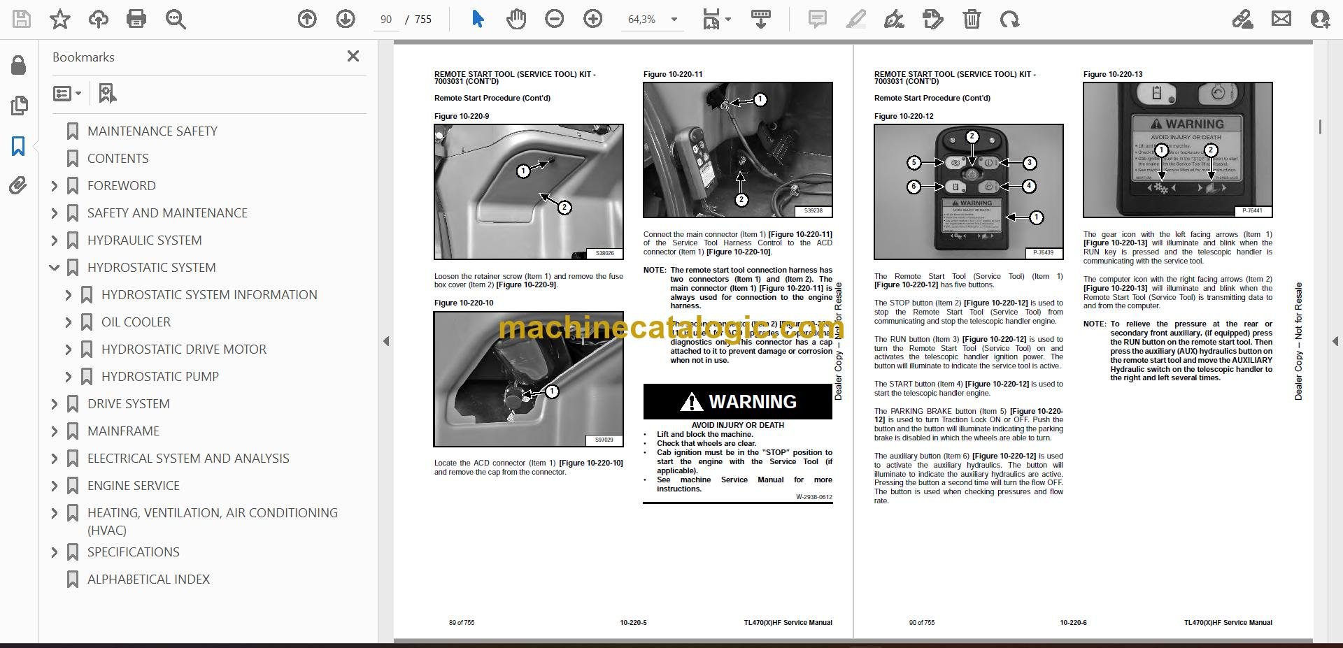
Q: Is this a searchable PDF with readable wiring diagrams?

A: These manuals are usually supplied as searchable PDFs, and the wiring diagrams are designed to be legible when zoomed on a laptop or tablet.

Q: How do I know it fits my exact machine?

A: Check your serial plate. If your TL470 VersaHANDLER TTC serial number falls between AVKM11001 and AVKM13999, this is the right manual.

Q: Is this what I need for real repairs, or just maintenance?

A: This is the workshop service manual, so it's aimed at diagnostics and repair work, not just routine maintenance.

Bottom line: If you're wrenching on a TL470 in that serial range and need real repair info, this is the manual you want. If you're just learning to run the machine, it's the wrong book.

📘 Show Index

Table of Contents:

  • MAINTENANCE SAFETY
  • CONTENTS
  • FOREWORD
    • FOREWORD
    • SAFETY INSTRUCTIONS
      • Safe Operation Is The Operator’s Responsibility
      • Safe Operation Needs A Qualified Operator
      • Avoid Silica Dust
      • Dismantling And Disposal
    • FIRE PREVENTION
      • Maintenance
      • Operation
      • Electrical
      • Hydraulic System
      • Fueling
      • Starting
      • Welding And Grinding
      • Fire Extinguishers
    • SERIAL NUMBER LOCATION
      • Telescopic Handler Statutory Plate
      • Engine Serial Number
      • Other Serial Numbers
    • DELIVERY REPORT
    • BOBCAT TELESCOPIC HANDLER IDENTIFICATION
  • SAFETY AND MAINTENANCE
    • LIFTING AND BLOCKING THE TELESCOPIC HANDLER
      • Procedure
    • OPERATOR CAB
      • Description
      • Cab Door
      • Cab Door Window
      • Rear Cab Window
      • Cab Light
    • TRANSPORTING THE TELESCOPIC HANDLER ON A TRAILER
      • Loading And Unloading
      • Fastening
    • TOWING THE TELESCOPIC HANDLER
      • Procedure
    • SERVICE SCHEDULE
      • Chart
    • AIR CLEANER SERVICE
      • Replacing Filter Elements
    • ENGINE COOLING SYSTEM
      • Cleaning
      • Checking Level
      • Removing And Replacing The Coolant
    • FUEL SYSTEM
      • Fuel Specifications
      • Biodiesel Blend Fuel
      • Filling The Fuel Tank
      • Primary Fuel Filter (Pre-Filter)
      • Secondary Fuel Filter
      • Removing Air From The Fuel System
    • ENGINE LUBRICATION SYSTEM
      • Checking And Adding Engine Oil
      • Engine Oil Chart
      • Removing And Replacing Oil And Filter
    • HYDRAULIC / HYDROSTATIC SYSTEM
      • Checking And Adding Fluid
      • Hydraulic / Hydrostatic Fluid Chart
      • Removing And Replacing Hydraulic Fluid
      • Removing And Replacing Hydraulic / Hydrostatic Filters
      • Removing And Replacing Hydraulic Charge Filter
      • Fill / Breather Cap
    • AXLES (FRONT AND REAR)
      • Checking And Adding Oil (Planetary Carrier)
      • Removing And Replacing Oil (Planetary Carrier)
      • Checking And Adding Oil (Rear Differential)
      • Removing And Replacing Oil (Rear Differential)
      • Checking And Adding Oil (Front Differential)
      • Removing And Replacing Oil (Front Differential)
      • Checking And Adding Oil (Gear Box)
      • Removing And Replacing Oil (Gear Box)
    • LUBRICATING THE TELESCOPIC HANDLER
      • Lubrication Locations
    • ATTACHMENT CARRIER
      • Inspection And Maintenance
    • TIRE MAINTENANCE
      • Wheel Nuts
      • Rotating
      • Mounting
      • Pressure
    • APPROVED BOOM STOP
      • Installing The Approved Boom Stop
      • Removing The Approved Boom Stop
    • ENGINE COVER
      • Opening And Closing
    • STOPPING THE ENGINE AND LEAVING THE TELESCOPIC HANDLER
      • Procedure
    • EMERGENCY EXIT
      • Rear Window
      • Right Rear Window
    • TELESCOPIC HANDLER STORAGE AND RETURN TO SERVICE
      • Storage
      • Return To Service
    • LIFTING THE TELESCOPIC HANDLER
      • Procedure
    • REMOTE START TOOL (SERVICE TOOL) KIT – MEL1563
      • Remote Start Tool – MEL1563
      • Service Tool Harness Control – MEL1565
      • Service Tool Harness Communicator – MEL1566
    • REMOTE START TOOL (SERVICE TOOL) KIT – 7003031
      • Remote Start Tool (Service Tool) – 7003030
      • Telescopic Handler Service Tool Harness – 6689747
      • Computer Service Tool Harness – 6689746
      • Remote Start Procedure
  • HYDRAULIC SYSTEM
    • HYDRAULIC / HYDROSTATIC SCHEMATICS
    • HYDRAULIC SYSTEM INFORMATION
      • Glossary Of Hydraulic / Hydrostatic Symbols
      • Troubleshooting Chart
      • Tightening Procedures
    • LIFT CYLINDER
      • Removal And Installation
      • Parts Identification
      • Disassembly
      • Assembly
    • SELF LEVELING CYLINDER
      • Removal And Installation
      • Parts Identification
      • Disassembly
      • Assembly
    • SELF LEVELING CYLINDER (LOCK VALVE)
      • Removal And Installation
    • EXTENSION CYLINDER
      • Cylinder Group Removal And Installation
      • Upper Tubeline Removal And Installation
      • Extension Cylinder Removal And Installation
      • Tubeline Tray Disassembly
      • Parts Identification
      • Disassembly
      • Assembly
    • TILT CYLINDER
      • Removal And Installation
      • Parts Identification
      • Disassembly
      • Assembly
    • STEERING CYLINDER (FRONT / REAR)
      • Removal
      • Installation
      • Disassembly
      • Assembly
    • GEAR CONTROL CYLINDER
      • Removal
      • Parts Identification
      • Disassembly
      • Assembly
      • Installation
    • MAIN RELIEF VALVE
      • Testing And Adjustment
      • Removal And Installation
    • MANIFOLD
      • Removal And Installation
      • Parts Identification
      • Disassembly And Assembly
    • BRAKE VALVE
      • Removal And Installation
    • PISTON PUMP
      • Test Tools Installation
      • Troubleshooting Chart
      • Removal And Installation
      • Parts Identification
      • Disassembly And Assembly
    • FAN MOTOR
      • Removal And Installation
      • Parts Identification (Single Speed Version) (Standard)
      • Disassembly And Assembly (Single Speed Version) (Standard)
      • Parts Identification (Variable Speed Version) (Optional)
      • Disassembly And Assembly (Variable Speed Version) (Optional)
    • HYDRAULIC FLUID RESERVOIR
      • Removal And Installation
    • STEERING VALVE
      • Removal And Installation
    • HYDRAULIC CONTROL VALVE
      • Troubleshooting Chart (Controllers)
      • Valve Section Troubleshooting
      • Troubleshooting Chart (Control Valve)
      • Removal And Installation
      • Parts Identification
      • Disassembly And Assembly
      • End Housing Disassembly And Assembly
      • Auxiliary Valve Section Disassembly And Assembly
      • Telescoping Valve Section Disassembly And Assembly
      • Tilting Valve Section Disassembly And Assembly
      • Lifting Valve Section Disassembly And Assembly
      • Inlet-Outlet Valve Section Disassembly And Assembly
    • PORT RELIEF VALVES
      • Testing
      • Replacement Procedure
    • PARKING BRAKE
      • Valve Removal And Installation
    • ACCUMULATOR
      • Removal And Installation
    • FAN PUMP
      • Removal And Installation
      • Disassembly And Assembly
  • HYDROSTATIC SYSTEM
    • HYDROSTATIC SYSTEM INFORMATION
      • Troubleshooting Chart
      • Replenishing Valve Function
    • OIL COOLER
      • Description
    • HYDROSTATIC DRIVE MOTOR
      • Removal And Installation
      • Parts Identification
      • Disassembly
      • Inspection
      • Assembly
    • HYDROSTATIC PUMP
      • Calibration
      • Swash Plate Calibration
      • Removal And Installation
      • Parts Identification
      • Shaft Disassembly
      • Relief Valves Disassembly And Assembly
      • Charge Pump Disassembly
      • Piston Pump Disassembly
      • Solenoid Block Disassembly
      • Inspection
      • Piston Pump Assembly
      • Charge Pump Assembly
      • Solenoid Block Assembly
      • Shaft Assembly
  • DRIVE SYSTEM
    • TROUBLESHOOTING
      • Chart
    • AXLE AND DIFFERENTIAL (FRONT)
      • Description
      • Planetary Carrier Parts Identification
      • Planetary Carrier Disassembly
      • Steering Knuckle And Drive Axle Parts Identification
      • Steering Knuckle Disassembly
      • Drive Axle Disassembly
      • Brake Group Parts Identification
      • Brake Group Disassembly
      • Differential Parts Identification
      • Differential Disassembly
      • Pinion Group Parts Identification
      • Pinion Group Disassembly
      • Pinion Group Assembly
      • Differential Assembly
      • Brake Group Assembly
      • Drive Axle Assembly
      • Steering Knuckle Assembly
      • Planetary Carrier Assembly
      • Special Tools
    • AXLE AND DIFFERENTIAL (REAR)
      • Description
      • Planetary Carrier Parts Identification
      • Planetary Carrier Disassembly
      • Steering Knuckle And Drive Axle Parts Identification
      • Steering Knuckle Disassembly
      • Differential Parts Identification
      • Differential Disassembly
      • Pinion Group Parts Identification
      • Pinion Group Disassembly
      • Pinion Group Assembly
      • Differential Assembly
      • Steering Knuckle Assembly
      • Planetary Carrier Assembly
      • Planetary Carrier Assembly
      • Special Tools
    • FRONT AXLE
      • Removal And Installation
    • AXLE TOE-IN
      • Adjustment
    • PARKING BRAKE
      • Releasing The Brake For Towing
      • Adjustment
      • Brake Cylinder Removal
      • Brake Cylinder Disassembly And Assembly
      • Brake Disc Removal And Installation
      • Brake Cylinder Installation
    • STEERING ANGLE ADJUSTMENT
      • Adjustment
    • DRIVESHAFT
      • Rear Driveshaft Removal And Installation
      • Front Driveshaft Removal And Installation
    • SERVICE BRAKE
      • Description
      • Bleeding The Brake Circuit
    • REAR AXLE
      • Removal And Installation
    • GEAR BOX
      • Removal And Installation
      • Parts Identification
      • Disassembly
      • Assembly
  • MAINFRAME
    • OPERATOR CAB
      • Removal And Installation
    • OPERATOR SEAT
      • Removal And Installation
    • FIXED BOOM
      • Removal
      • Installation
    • INNER BOOM
      • Removal And Installation
    • WEAR PADS (FRONT)
      • Removal And Installation
    • WEAR PADS (REAR)
      • Removal And Installation
    • ENGINE COVER
      • Gas Cylinder Removal And Installation
      • Removal And Installation
    • FUEL TANK
      • Removal And Installation
    • ATTACHMENT CARRIER (QUICK-TACH)
      • Removal And Installation
    • COUNTERWEIGHT
      • Removal And Installation
    • FENDER
      • Removal And Installation
    • STEERING COLUMN COVER
      • Removal And Installation
    • DASH COVER
      • Removal And Installation
    • JOYSTICK PANEL
      • Removal And Installation
  • ELECTRICAL SYSTEM AND ANALYSIS
    • ELECTRICAL SCHEMATICS
    • ELECTRICAL SYSTEM INFORMATION
      • Troubleshooting Chart
      • Description
      • Fuses And Relay Location / Identification
    • BATTERY
      • Removal And Installation Battery
      • Using A Booster Battery (Jump Starting)
      • Battery Maintenance
    • ALTERNATOR
      • Removal And Installation
      • Belt Adjustment
      • Belt Replacement
    • STARTER
      • Testing
      • Removal And Installation
    • LIGHTS
      • Rear Light Removal And Installation
      • Rear Light Bulb Replacement
      • Front Light Removal And Installation
      • Front Light Bulb Replacement
    • SIGNAL LEVER
      • Removal And Installation
    • DISPLAY
      • Removal And Installation
    • INSTRUMENT PANELS
      • Right Instrument And Indicator Panel Removal And Installation
      • Left Instrument Panel Removal And Installation
    • BOOM ANGLE SENSOR
      • Removal And Installation
      • Calibration
    • FRONT WIPER MOTOR
      • Removal And Installation
    • TOP WIPER MOTOR
      • Removal And Installation
    • REAR WIPER MOTOR
      • Removal And Installation
    • PEDAL ASSEMBLY
      • Removal And Installation
    • INCHING SENSOR
      • Removal And Installation
      • Calibration
    • SERVICE PC (LAPTOP COMPUTER)
      • Connecting Remote Start Tool (Service Tool) – MEL1563
      • Connecting Remote Start Tool (Service Tool) – 7003030
    • FUEL LEVEL SENDER
      • Removal And Installation
    • JOYSTICK
      • Removal And Installation
    • LLMI / LLMC SYSTEM
      • System Components Identification
      • Longitudinal Load Moment Indicator (LLMI) Description
      • Longitudinal Load Moment Controller (LLMC)
      • Longitudinal Load Moment Controller (LLMC) Override Switch
      • LLMC Calibration Test
      • LLMI / LLMC Calibration
      • LLMI / LLMC Troubleshooting
      • LLMS Removal
      • LLMS Installation
      • LLMC Removal And Installation
  • ENGINE SERVICE
    • ENGINE INFORMATION
      • Fuel System Information
      • Specifications
      • Troubleshooting
      • Engine Removal And Installation
    • ENGINE AND HYDROSTAT ASSEMBLY
      • Removal And Installation
    • ENGINE SPEED CONTROL
      • Removal And Installation
    • MUFFLER
      • Removal And Installation
    • AIR CLEANER
      • Housing Removal And Installation
    • ENGINE COOLING SYSTEM
      • Oil Cooler / Intercooler / Radiator Removal And Installation
      • Water Temperature Regulator Removal
      • Water Temperature Regulator Installation
      • Water Temperature Regulator Test
      • Cooling System Check
      • Cooling System Inspection
      • Engine Oil Cooler Removal
      • Engine Oil Cooler Installation
      • Engine Oil Cooler Inspection
      • Water Pump Removal
      • Water Pump Installation
      • Water Pump Inspection
      • Water Pump Bypass Tube Removal
      • Water Pump Bypass Tube Installation
      • Expansion Tank Removal And Installation
    • LUBRICATION SYSTEM
      • Engine Oil Filter Base Removal
      • Engine Oil Filter Base Installation
      • Engine Oil Pressure Test
      • Excessive Engine Oil Consumption Inspection
      • Increased Engine Oil Temperature Inspection
      • Excessive Bearing Wear Inspection
    • FUEL SYSTEM
      • Fuel Priming Pump Removal
      • Fuel Priming Pump Installation
      • Fuel System Inspection
      • Fuel Quality Test
      • Fuel System Prime
    • CYLINDER HEAD
      • Valve Mechanism Cover Removal
      • Valve Mechanism Cover Installation
      • Air Inlet And Exhaust System Inspection
    • CRANKSHAFT SEALS AND BEARINGS
      • Crankshaft Rear Seal Removal
      • Crankshaft Rear Seal Installation
      • Crankshaft Wear Sleeve (Rear) Removal
      • Crankshaft Wear Sleeve (Rear) Installation
      • Crankshaft Front Seal Removal
      • Crankshaft Front Seal Installation
      • Crankshaft Wear Sleeve (Front) Removal
      • Crankshaft Wear Sleeve (Front) Installation
    • TIMING COVER
      • Timing Cover Removal
      • Timing Cover Installation
    • CRANKSHAFT PULLEY
      • Crankshaft Pulley Removal
      • Crankshaft Pulley Installation
      • Crankshaft Pulley Check
    • TURBOCHARGER
      • Troubleshooting
      • Description
      • Removal And Installation
    • FLYWHEEL AND HOUSING
      • Flywheel Removal
      • Flywheel Installation
      • Flywheel Inspection
      • Flywheel Housing Removal
      • Flywheel Housing Installation
      • Flywheel Housing Inspection
      • Crankcase Breather Removal
      • Crankcase Breather Installation
    • ELECTRONIC CONTROL MODULE
      • Removal
      • Installation
      • Mounting Bracket Removal
      • Mounting Bracket Installation
  • HEATING, VENTILATION, AIR CONDITIONING (HVAC)
    • AIR CONDITIONING SYSTEM FLOW
      • Description
      • Chart
      • Components
      • Safety Equipment
    • REGULAR MAINTENANCE
      • Filters
      • Air Conditioning Belt Adjustment
      • Belt Replacement
      • Cleaning The Condenser
      • Air Conditioning Lubrication
      • Air Conditioning Service Chart
      • Evaporator / Heater Coil
    • TROUBLESHOOTING
      • Blower Motor Does Not Operate
      • Blower Motor Operates Normally, But Air Flow Is Insufficient
      • Insufficient Cooling Although Air Flow And Compressor Operation Are Normal
      • The Compressor Does Not Operate At All, Or Operates Improperly
      • Gauge Pressure Related Troubleshooting
      • Temperature / Pressure Chart
      • Poor A/C Performance
      • HVAC Repair And Leaks
      • Electrical System
    • SYSTEM CHARGING AND RECLAMATION
      • Reclamation And Charging With Recovery / Charging Unit
    • COMPRESSOR
      • Removal And Installation
      • Oil
      • Oil Check
      • Clutch Disassembly And Assembly
    • CONDENSER
      • Removal And Installation
    • RECEIVER / DRIER
      • Removal And Installation
    • PRESSURE SWITCH
      • Removal And Installation
    • EVAPORATOR / HEATER UNIT
      • Removal And Installation
    • THERMOSTAT
      • Description
      • Removal And Installation
    • EXPANSION VALVE
      • Removal And Installation
  • SPECIFICATIONS
    • (TL470(X)HF) TELESCOPIC HANDLER SPECIFICATIONS
      • Machine Dimensions
      • Performance
      • Weights
      • Engine
      • Controls
      • Drive System
      • Traction
      • Steering
      • Brakes
      • Fluid Capacities
      • Hydraulic System
      • Cycle Times
      • Electrical System
      • Temperature Range
      • Altitude
      • Instrument Panel
      • Environmental
    • MACHINE TORQUE SPECIFICATIONS
      • Axle
      • Boom
      • Drive Box
      • Drive Motor
      • Engine
      • Hydraulic Pump
    • TORQUE SPECIFICATIONS FOR BOLTS
      • Torque for General SAE Bolts
      • Torque For General Metric Bolts
    • HYDRAULIC CONNECTION SPECIFICATIONS
      • O-ring Face Seal Connection
      • Straight Thread O-ring Fitting
      • Tubelines And Hoses
      • Flare Fitting
      • O-ring Flare Fitting
      • Port Seal Fitting
    • HYDRAULIC / HYDROSTATIC FLUID SPECIFICATIONS
      • Specifications
    • CONVERSIONS
      • Decimal And Millimeter Equivalent Chart
      • U.S. To Metric Conversion Chart
    • SERVICE TOOLS REQUIRED
      • Remote Start Tools
      • Hydraulic Tools
      • Drive Tools
      • Electrical Tools
      • Engine Tools
      • HVAC Tools
  • ALPHABETICAL INDEX

Bobcat Software

Bobcat PDF Manuals

Related Manuals

0
    0
    Your Cart
    Your cart is emptyReturn to Shop