Cat 6040 Hydraulic Shovel Service Manual (EM030743-5) (SN CC900401-UP, ELZ00101-UP)
These 6040 hydraulic shovels usually live in hard rock pits and big earthmoving jobs, running long shifts in dust, mud, and cold starts. This service manual walks you through how to trace faults, verify what’s actually failed, and then tear down and rebuild without guessing. Say the boom’s moving slow and the operator swears it’s “low hydraulics” – with this book you’ll trace the circuit, check pressures at the right ports, isolate whether it’s a pump, valve, or sensor, and only then start ordering parts.
Applications & Use Cases
- Track down hydraulic drift by following the test sequence, then inspect cylinders, control valves, and lines before you crack anything open.
- Chase an electrical fault by routing through the proper schematics, testing connectors and switches in order instead of poking around randomly.
- Verify a suspected pump failure using the manual’s step-by-step flow and pressure checks so you don’t replace an expensive unit that’s actually fine.
- Align and adjust travel and swing functions after component changes, using the given procedures to test and fine‑tune operation.
- Bleed and restart systems safely after hose, cylinder, or component work, so you don’t trap air and create new problems.
FAQ
Q: Is this a searchable PDF, or just page scans?
A: It’s typically a searchable PDF, so you can jump to systems, test steps, or keywords pretty fast.
Q: Can I print just the sections I need for the field?
A: Yes, most folks print the job-specific procedures, stick them in a binder, and keep the full file on a laptop or tablet in the service truck.
Safety Note
Always de-energize, lock out, and bleed hydraulic pressure before you crack a line or pull a component on a 6040.
Cat 6040 Hydraulic Shovel Index:
- 1. General
- 1.1 Introduction
- 1.1.1 Service Manual
- 1.1.2 How to use the Service Manual
- 1.1.3 Servicing and repair
- 1.1.4 Important hints
- 1.2 Safety instructions
- 1.2.1 Risks of disregarding safety instructions
- 1.2.2 Safety regulations
- 1.2.3 Modification of the machine
- 1.2.4 Re- commissioning
- 1.3 General
- 2. Technical Data
- 2.1 Introduction
- 2.1.1 Foreword
- 2.1.2 Safety
- 2.1.3 General
- 2.2 Engine / Motor
- 2.3 Hydraulic system
- 2.3.1 Main pump
- 2.3.2 Swing system
- 2.3.3 Servo pump
- 2.3.4 Cooling system hydraulic oil / water
- 2.3.5 Travel motor
- 2.3.6 Control block
- 2.3.7 Filter elements for hydraulic system
- 2.4 Pressure setting
- 2.5 Governing current for proportional valves
- 2.6 Hydraulic cylinder
- 2.6.1 Face shovel
- 2.6.2 Backhoe
- 2.7 Transmission ratio
- 2.8 Weights of modules and components
- 2.8.1 Modules
- 2.8.2 Components
- 2.9 Tightening procedures for bolts
- 2.9.1 Tightening procedures for module bolts
- 2.9.2 Tightening procedures for component bolts
- 3. Tools, Assembly
- 3.1 Introduction
- 3.1.1 Foreword
- 3.1.2 Safety
- 3.1.3 General
- 3.1.4 Corrosion protection for pins and bearings
- 3.2 Tools
- 3.3 Assembling the excavator
- 3.3.1 Overview
- 3.3.2 Safety instructions
- 3.3.3 Personnel
- 3.3.4 Assembly equipment
- 3.3.5 Boom installation
- 3.3.6 Modules on arrival
- 3.3.7 Assembly site
- 3.3.8 Preparation of modules for assembly
- 3.3.9 General assembly procedures
- 3.3.10 Workflow chart of assembly procedure
- 3.3.11 Preparation of undercarriage and superstructure modules
- 3.3.12 Undercarriage assembly
- 3.3.13 Preparations for superstructure installation
- 3.3.14 Installation of superstructure frame
- 3.3.15 Installation of swing gearboxes
- 3.3.16 Connection of hydraulic lines between undercarriage and superstructure
- 3.3.17 Installation of modules and components to superstructure frame
- 3.3.18 Stick installation Boom preparation
- 3.3.19 Final steps of boom
- 3.3.20 Top up operating fluids
- 3.3.21 Electric system
- 3.3.22 Preparations for machine start-up
- 3.3.23 Machine start-up
- 3.3.24 Bucket installation
- 3.3.25 Final preparations for machine start-up
- 4. Undercarriage
- 4.1 Introduction
- 4.1.1 Foreword
- 4.1.2 Safety
- 4.1.3 General
- 4.2 Travel system
- 4.2.1 General
- 4.2.2 Components of travel system
- 4.2.3 Wear limits
- 4.3 Track chain
- 4.3.1 General
- 4.3.2 Components of Track chain
- 4.3.3 Assembly
- 4.3.3.1 Opening the track chain
- 4.3.3.2 Closing the track chain
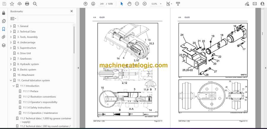
- 4.4 Idler
- 4.4.1 General
- 4.4.2 Components of the idler
- 4.4.3 Assembly of the idler
- 4.5 Bottom roller
- 4.5.1 General
- 4.5.2 Components of the bottom roller
- 4.5.3 Bottom roller installation
- 4.5.4 Bottom roller assembly
- 4.6 Top roller
- 4.6.1 General
- 4.6.2 Top roller components
- 4.6.3 Top roller installation
- 4.6.4 Top roller assembly
- 4.7 Sprocket
- 4.8 Travel gearbox – removal and installation
- 4.9 Track pads
- 4.10 Hydraulic track tensioning system
- 4.10.1 General
- 4.10.2 Components
- 4.10.3 Releasing the track tension
- 4.10.4 Checking the accumulators
- 4.11 Duo cone seals
- 5. Superstructure
- 5.1 Introduction
- 5.1.1 Foreword
- 5.1.2 Safety
- 5.1.3 General
- 5.2 Swing ring
- 5.2.1 General
- 5.2.2 Components of swing bearing
- 5.2.3 Hardness gap, “S – point’’
- 5.2.4 Fitting the swing bearing onto the undercarriage
- 5.2.5 Fitting the swing bearing onto the undercarriage
- 5.3 Engine / Motor installation
- 5.3.1 Engine mounting
- 5.3.2 Radiator installation
- 5.3.3 Radiator fan installation
- 5.4 Engine / Motor coupling
- 5.5 Swing gearbox – removal and installation
- 5.6 Pump gearbox – removal and installation
- 5.7 Hydraulic pumps – installation
- 5.8 Oil cooler – installation
- 5.9 Rotor – installation
- 6. Drive Unit
- 7. Gearboxes
- 7.1 Introduction
- 7.1.1 Foreword
- 7.1.2 Safety instructions
- 7.1.3 General
- 7.1.4 Checking procedures
- 7.1.5 Hubs and bearings
- 7.1.6 Fitting of toroidal sealing rings in gearboxes
- 7.2 Travel gearbox
- 7.2.1 General
- 7.2.2 Dismantling and installing the travel gearbox
- 7.2.3 Disassembly and Assembly Instructions for the gearbox
- 7.3 Swing gearbox
- 7.3.1 General
- 7.3.2 Dismantling and installing the swing gearbox
- 7.3.3 Disassembly and Assembly Instructions
- 7.4 Pump gearbox
- 7.4.1 General
- 7.4.2 Dismantling and installing the pump gearbox
- 7.4.3 Disassembly and Assembly Instructions
- 8. Hydraulic system
- 8.1 Introduction
- 8.1.1 Foreword
- 8.1.2 Safety
- 8.1.3 General
- 8.2 Depressurizing, bleeding, flushing
- 8.2.1 Depressurizing of the hydraulic system
- 8.2.1.1 Depressurization of the attachment circuits
- 8.2.1.2 Depressurization of the engine off lowering accumulator
- 8.2.1.3 Depressurization of track tension circuit
- 8.2.1.4 Depressurization of swing circuit
- 8.2.1.5 Depressurization of access ladder circuit
- 8.2.2 Bleeding of the hydraulic system
- 8.2.2.1 Bleeding air from hydraulic pumps
- 8.2.2.2 Bleeding air from the main pumps
- 8.2.2.3 Bleeding air from the swing pumps
- 8.2.2.4 Bleeding air from the charge pumps
- 8.2.2.5 Bleeding air from the hydraulic oil fan pumps
- 8.2.2.6 Bleeding air from the pilot pumps
- 8.2.2.7 Bleeding air from the hydraulic oil circulation pumps
- 8.2.2.8 Bleeding air from hydraulic motors
- 8.2.2.9 Bleeding air from swing motors
- 8.2.2.10 Bleeding air from hydraulic cylinders
- 8.2.2.11 Bleeding air from pilot pressure circuit
- 8.2.3 Flushing of the hydraulic system
- 8.3 Hydraulic circuit diagram
- 8.3.1 Technical data
- 8.3.2 Components of the hydraulic schematic
- 8.3.3 Components of the hydraulic system
- 8.3.4 Hydraulic schematic
- 8.4 Hydraulic components
- 8.4.1 Main pumps
- 8.4.2 Swing pump
- 8.4.3 Pilot pumps
- 8.4.4 Charge pumps
- 8.4.5 Hydraulic oil cooling fanpumps
- 8.4.6 Engine cooling fan pumps
- 8.4.7 Circulation pumps
- 8.4.8 Lubrication (grease) pumps
- 8.4.9 Rotor
- 8.4.10 Hydraulic valves
- 8.5 Description of hydraulic circuits
- 8.5.1 Main pump flow regulation
- 8.5.2 Pressure cut-off
- 8.5.3 Servo system
- 8.5.4 Attachment functions (BH)
- 8.5.5 Travel system
- 8.5.6 Swing system
- 8.5.7 Track tensioning system
- 8.5.8 Cooling system for hydraulic oil
- 8.5.9 Cooling system for engines
- 8.5.10 Cooling system for pump gearbox
- 8.6 Pressure checking and setting
- 8.6.1 Introduction
- 8.6.1.1 Foreword
- 8.6.1.2 Safety
- 8.6.1.3 General
- 8.6.2 Pressure settings
- 8.6.3 Tools
- 8.6.4 Hydraulic circuits
- 8.6.4.1 Pilot pressure system
- 8.6.4.2 Main pump flow control
- 8.6.4.3 Pressure cut-off system
- 8.6.4.4 Primary relief system
- 8.6.4.5 Secondary relief system for attachment
- 8.6.4.6 Secondary relief system for travel
- 8.6.4.7 Swing system
- 8.6.4.8 Track tensioning system
- 8.6.4.9 Cooling system for hydraulic oil
- 8.6.4.10 Cooling system for engines
- 8.6.4.11 Hydraulic accumulators
- 8.7 Installation of hydraulic pumps
- 8.7.1 General
- 8.7.2 Components
- 8.7.3 Removal and installation of the hydraulic pumps
- 8.8 Hydraulic cylinders backhoe
- 8.8.1 Boom cylinder
- 8.8.1.1 Preface
- 8.8.1.2 Product Description
- 8.8.1.3 Safety Instructions
- 8.8.1.4 Description of Cylinder Type and Components
- 8.8.1.5 Storage, Start-up and Maintenance
- 8.8.1.6 Hydraulic Cylinder Spare Parts
- 8.8.1.7 List of Required Tools
- 8.8.1.8 Dismantling Instructions
- 8.8.1.9 Assembly Instructions
- 8.8.2 Stick cylinder
- 8.8.2.1 Preface
- 8.8.2.2 Product Description
- 8.8.2.3 Safety Instructions
- 8.8.2.4 Description of Cylinder Type and Components
- 8.8.2.5 Storage, Start-up and Maintenance
- 8.8.2.6 Hydraulic Cylinder Spare Parts
- 8.8.2.7 List of Required Tools
- 8.8.2.8 Dismantling Instructions
- 8.8.2.9 Assembly Instructions
- 8.8.3 Bucket cylinder
- 8.8.3.1 Preface
- 8.8.3.2 Product Description
- 8.8.3.3 Safety Instructions
- 8.8.3.4 Description of Cylinder Type and Components
- 8.8.3.5 Storage, Start-up and Maintenance
- 8.8.3.6 Hydraulic Cylinder Spare Parts
- 8.8.3.7 List of Required Tools
- 8.8.3.8 Dismantling Instructions
- 8.8.3.9 Assembly Instructions
- 9. Electric system
- 9.1 Introduction
- 9.1.1 Foreword
- 9.1.2 Safety instructions
- 9.1.3 General
- 9.2 Electric System – 24 Volt
- 9.2.1 Overview of switch cabinets
- 9.2.2 Electrical documentation
- 9.2.2.1 Naming of electrical components
- 9.2.2.2 Layout drawing
- 9.2.3 List of electrical components
- 9.2.4 Circuit diagram
- 9.2.5 Connection tables – terminal strips
- 9.2.6 Connection tables – plug connections
- 9.2.7 Schematic symbols
- 9.3 Control And Monitoring Platform (CAMP)
- 9.3.1 Introduction to CAMP
- 9.3.2 Overview of the individual control systems
- 9.3.3 Location of the main components
- 9.3.4 Servo Control System (SCS)
- 9.3.4.1 Introduction with basic functions
- 9.3.4.2 Technical data
- 9.3.4.3 Terminal plan (connectors)
- 9.3.4.5 Installation and removal
- 9.3.5 Auxiliary System (AS)
- 9.3.5.1 Introduction with basic functions
- 9.3.5.2 Technical data
- 9.3.5.3 Terminal plan (connectors)
- 9.3.5.4 Installation and removal
- 9.3.5.5 Settings and adjustments
- 9.3.6 Drive Controller Left Hand (DCLH)
- 9.3.6.1 Introduction with basic functions
- 9.3.6.2 Technical data
- 9.3.6.3 Terminal plan (connectors)
- 9.3.6.4 Data exchange
- 9.3.6.5 Installation and removal
- 9.3.6.6 Settings and adjustments
- 9.3.7 Drive Controller Right Hand (DCRH)
- 9.3.7.1 Introduction with basic functions
- 9.3.7.2 Technical data
- 9.3.7.3 Terminal plan (connectors)
- 9.3.7.4 Data exchange
- 9.3.7.5 Installation and removal
- 9.3.7.6 Settings and adjustments
- 9.3.8 Board Control System (BCS)
- 9.3.8.1 Introduction with basic functions
- 9.3.8.2 Technical data
- 9.3.8.3 Terminal plan (connectors)
- 9.3.8.4 Installation and removal
- 9.3.8.5 Settings and adjustments
- 9.3.8.6 Changing the program
- 9.4 Communication and control loops within CAMP
- 9.4.1 Controller Area Network (CAN)
- 9.4.1.1 CAN bus systems
- 9.4.1.2 Technical data of the CAN bus
- 9.4.1.3 CAN bus troubleshooting
- 9.4.2 Electronic Hydraulic Servo Control (EHSC)
- 9.4.2.1 Proportional valve block
- 9.4.3 Hand Levers and Pedals
- 9.4.3.1 Installing and removing
- 9.4.3.2 Settings
- 9.4.4 Pump flow regulation
- 9.4.4.1 Overview pump control
- 9.4.4.2 Data transfer
- 9.4.4.3 Reducing the Pump Control current / pressure
- 9.4.4.4 Overview hydraulic oil cooling
- 9.4.4.5 Overview engine cooling
- 9.4.5 Lubrication system
- 9.4.5.1 Lubrication system upper carriage
- 9.4.6 Lights
- 9.5 Electric Components
- 9.5.1 Location of components
- 9.5.1.1 Left engine
- 9.5.1.2 Right engine
- 9.5.1.3 Hydraulic oil tank
- 9.5.1.4 Swing engine
- 9.5.1.5 Ladder
- 9.5.1.6 Tank lift
- 9.5.2 List of components
- 9.5.2.1 Relay single contact
- 9.5.2.2 Relay single contact
- 9.5.2.3 Relay double contact
- 9.5.2.4 Contamination switch
- 9.5.2.5 Contamination switch
- 9.5.2.6 Cable for controller
- 9.5.2.7 Controller
- 9.5.2.8 Pressure sensor (0-400bar)
- 9.5.2.9 Pressure sensor (0-2,5bar)
- 9.5.2.10 Pressure sensor (0-100bar)
- 9.5.2.11 Temperature sensor
- 9.5.2.12 Proximity switch
- 9.5.2.13 Switch / Spring loaded one side
- 9.5.2.14 Switch / Spring loaded two sides
- 9.5.2.15 Switch one side
- 9.5.2.16 Switch one side 2pin
- 9.5.2.17 Switch wiper
- 9.5.2.18 Slewing gear level sensor
- 9.5.2.19 Temperature switch swing/main pump
- 9.5.2.20 Pressure switch 20 bar
- 9.5.2.21 Float Switch / Bedia Sensor / Gearbox minimum
- 9.5.2.22 Fuel Level sensor
- 9.5.2.23 Relay / battery main switch
- 9.5.2.24 Float switch / Bedia Sensor
- 9.5.2.25 Float switch / Bedia Sensor water level
- 9.5.2.26 Pressure switch 0,5 bar
- 9.5.2.27 Pressure switch air cleaner
- 9.5.2.28 Relay 24V max 150A
- 9.5.2.29 Relay 24V max 50A
- 9.5.2.30 Diode
- 9.5.2.31 Diode
- 9.5.2.32 Voltage converter 24V / 12V
- 9.5.2.33 Initiator cut off system
- 9.5.2.34 Seat contact switch
- 9.5.2.35 Servo block proportional valve
- 9.5.2.36 Seat contact valve servo block
- 9.5.2.37 Track tensioning valve servo block
- 9.5.2.38 Plug 64 PIN
- 9.5.2.39 Plug 40 PIN
- 9.5.2.40 Plug 6 PIN
- 9.5.2.41 Proportional valve pump
- 9.5.2.42 Proportional valve pump regulation
- 9.5.2.43 Grease container level sensor (empty)
- 9.5.2.44 Grease container level sensor (full)
- 9.5.2.45 Initiator grease system
- 9.6 BCS Software
- 9.6.1 Overview of the menus
- 9.6.2 Start screen
- 9.6.3 Service menus
- 9.6.4 Fault storage menus
- 9.6.5 Setup menus
- 9.7 Troubleshooting
- 9.7.1 Safety instructions
- 9.7.2 General troubleshooting
- 9.7.2.1 General troubleshooting procedure
- 9.7.2.1 General troubleshooting procedure
- 9.7.2.3 Testing electrical components
- 9.7.2.4 Actions requiring special tools
- 9.7.2.5 Individual problems
- 9.7.3 Specific troubleshooting per error–ID
- 10. Attachment
- 11. Central lubrication system
- 11.1 Introduction
- 11.1.1 Preface
- 11.1.2 Illustration conventions
- 11.1.3 Operator’s responsibility
- 11.1.4 Safety instructions
- 11.1.5 Operation / maintenance
- 11.2 Technical data ( 1,000 kg grease container – supply)
- 11.2 Technical data ( 280 kg round container / 180 kg grease drum – supply)
- 11.3 Design of the central lubrication system
- 11.3.1 Functional diagram
- 11.3.2 Component arrangement
- 11.3.3 Distributor design
- 11.4 System function
- 11.4.1 Central lubrication system
- 11.4.1.1 Design
- 11.4.1.2 Operation sequence
- 11.4.2 Lubricant distributor
- 11.4.2.1 Functional sequence distributor type VSL / VSG
- 11.4.2.2 Functional sequence with progressive distributor type SSVD
- 11.4.3 Control unit
- 11.4.3.1 Arrangement of the components for upper carriage lubrication
- 11.4.3.2 Operating sequence
- 11.4.4 Grease pump
- 11.4.4.1 Start-up
- 11.4.4.2 Operation sequence
- 11.4.5 Electrical function
- 11.5 Lubrication system test
- 11.7 Setting of the lubrication and break times
- 11.7.1 Duration of a lubrication cycle for the upper carriage in normal operation
- 11.7.2 The functions of the reset button
- 11.7.3 Greasing cycle: Greasing of the superstructure
- 11.8 Bleeding of the central lubrication system
- 11.9 Repairing the lubrication pump
- 11.9.1 Components
- 11.9.2 Disassembly
- 11.9.3 Assembly
- 11.9.4 Spare parts
- 11.10 Repair of the lubrication distributors
- 11.11 Renewal of high pressure hose lines
- 11.12 Troubleshooting guideline
- 12. Options
- 15. Service Manual for fundamental principles of electricity (refer to Media No. EM030761)
- 16. Service Manual for handling circuit diagrams (refer to Media No. EM030771)
- 17. Service Manual for general information, conversion calculations and tightening torques (refer to Media No. EM030780)
- 18. Service Manual for sealing, protective, testing and cleaning agents (refer to Media No. EM030782)
- 19. Service Manual for fittings, tube assemblies and hose assemblies (refer to Media No. EM030784)
- 20. Repair welding manual (refer to Media No. EM010641)
- 21. Service Manual for oil samples and oil analysis (refer to Media No. EM030788)
Caterpillar


