A self-propelled modular transporter moves loads that no truck can carry, and the MSPE power pack is the diesel unit that drives its hydraulic and electrical systems. When that unit throws a fault, the person with the meter needs the drawings. This set suits an electrician who has to trace a circuit from the supply and fuse to the sensor or valve, one sheet at a time.
What these schematics help you do
- Trace the power supply (C4001) and the power supply command through to the alternator and starting motor.
- Check the emergency key and emergency control circuits when the unit won't start or won't hold.
- Follow the CAN BUS4 CAN L wiring and the analogic input-output card ETN-53/S on the electric box.
- Locate the wiring for electric box EB3, the EB3 box cable layout and the cable lamp layout (EB1) before you replace a harness.
- Identify hydraulic pump and tank details on the pump tank schematic, then confirm the part on the component list.
Who this is for
Electricians and field service technicians who diagnose faults on heavy-haul power packs. You get the wiring sheets and hydraulic drawings to work from at the machine, instead of tracing wires by hand.
FAQ
Q: What do I receive and how is it organised?
A: You get the set: 8 PDF files, 377 pages in total, in English and Italian. The main manual is the MSPE Power Pack Electrical System Schematics, drawing 360470503 (178 pages). The other seven are the Electric System Index (2 pages), MSPE Power Pack Electric System Schematics drawing 360470502 (168 pages), MSPE Remote Diagnostics Electrical System (14 pages), Power Pack General System (2 pages), Power Pack General System Drawings (8 pages), Power Pack Hydraulic Pump Tank Schematic (4 pages) and MSPE Magnetic Box Light Wiring (1 page).
Q: Which machine does it fit?
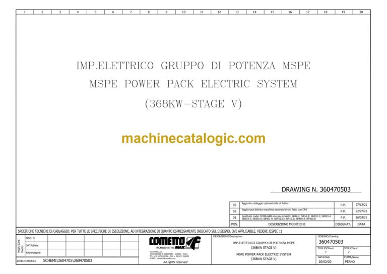
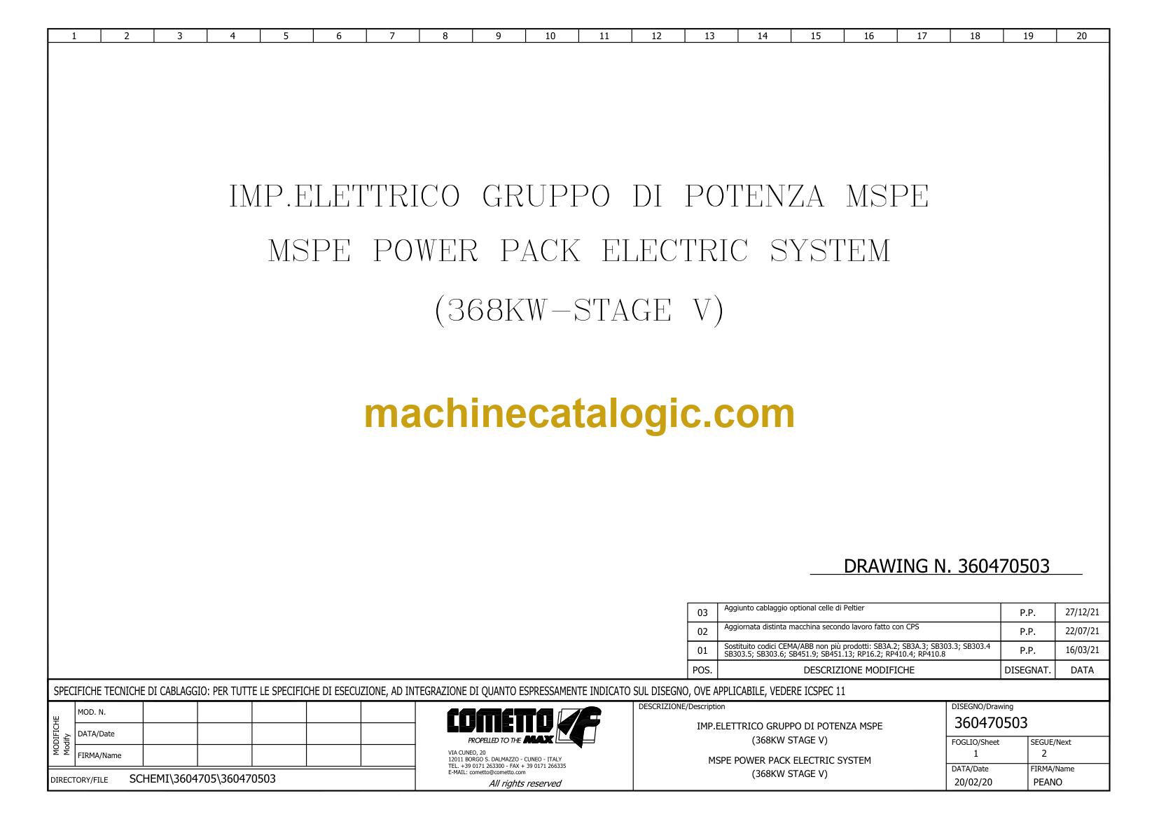
A: The Cometto MSPE Power Pack 368 kW. The main manual cover shows serial numbers 15838 and 15839, and the publication number is 360470503.
Q: How does it fit my job?
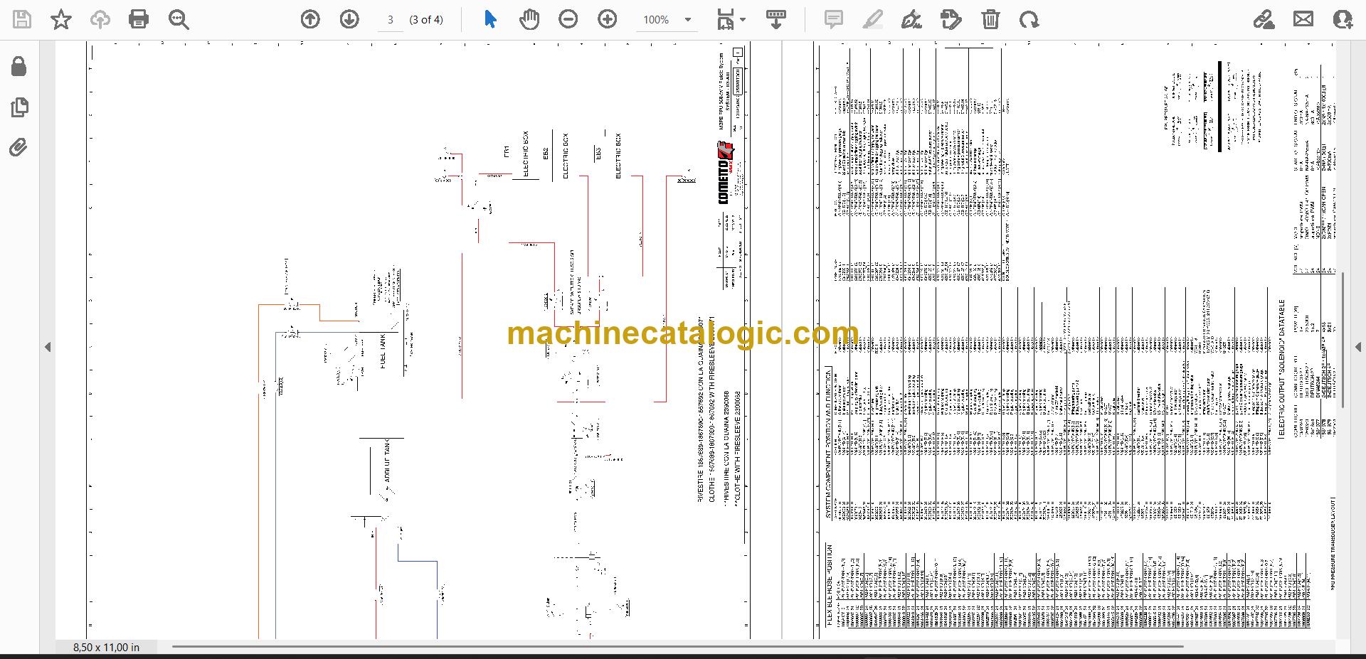
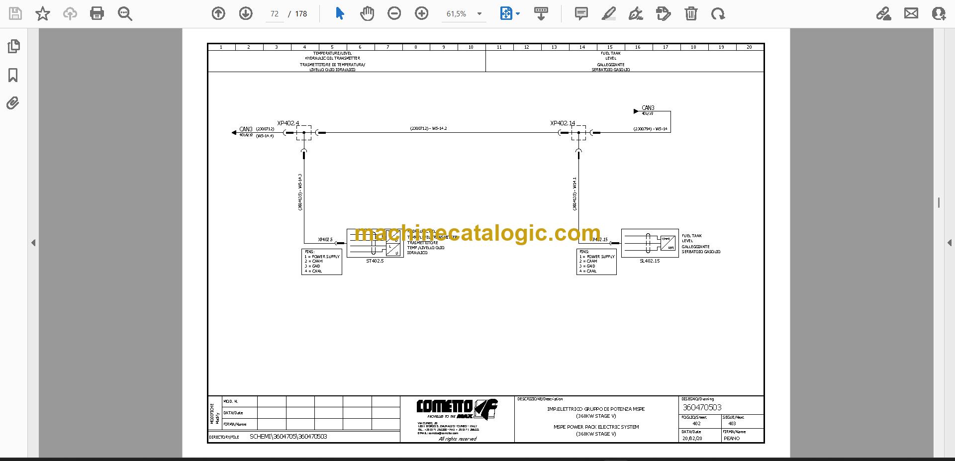
A: If you're chasing a fault, swapping a control box or sensor, or filing drawings for a unit that came in without them, the sheets give you the circuit path and the component list names the parts.
Match your serial number to 15838 or 15839, and you can start tracing from the fuse.
Click here to view the preview (PDF)
Do these schematics fit your machine?
| Model |
Serial No. |
| MSPE Power Pack 368 kW |
15838, 15839 |
The serial number shown is the one printed on the manual cover. Check the model and serial number on your machine's data plate before ordering.
📘 Show Index
Table of Contents:
- MSPE Power Pack Electrical System Schematics, drawing 360470503 (178 pages)
- Waiting before open
- Battery switch W.L
- General supply
- Vehicle charging power
- Connectors broken down
- Alternator
- Connection input-output card
- Circuit
- Emergency stop
- Power supply command
- Power supply
- Supply under-key
- Supply command supply
- Starting motor relay
- Starting motor
- Power supply diesel oil
- Emergency starting on
- Heater command
- Power supply (C4001)
- Power supply (C4002)
- Power supply (C4071)
- Control unit (S8)
- Unit' control
- Emergency key
- Warning light
- Engine on
- Latching key emergency
- Control motor
- Emergency control
- Direction indicator, stop lights
- FOG light supply
- Reverse drive warning horn and light
- And electric horn supply
- Emergency remote control
- Lights side left
- Side-marker
- Lights side right
- Light vehicle side
- Light rear side
- Electric box
- Command lights
- Electric box side
- Fuel tank
- Electric box front
- On the EB1 panel
- Electric box EB2
- Electric box EB3
- Motor in
- Relay for waiting before open
- Pressure increase socket
- Display electronic
- Electronic display
- Control motor diesel
- Cooling KIT (optional)
- Cooling fan
- Air cooling
- EB1 electric box
- Hydr. oil supply cable
- Power supply (low power)
- Selector switch
- Service
- System (optional)
- On the EB1
- CAN1H
- Vehicle coupling
- Vehicle coupling connector
- Coupling connector
- Local bus connector
- Connector local bus
- Remote control
- +24V power supply
- Input-output card ETN-45 address 226 on the electric box
- Connection on terminal board
- Input-output card ETN-45 address 227 on the electric box
- Lifting valve and transducers
- Pilotage proportional valve
- Hydraulic engine
- Temperature/level
- Hydraulic oil transmitter
- Level
- Pressure transducer point D
- PPU pressure transducer layout
- Analogic input-output card ETN-53/S address 229 on the electric box
- Analogic input-output card ETN-53/S address 230 on the electric box
- Input-output card ETN-40/S address 233 on the electric box
- PPU electric installation review
- Left side
- Push-button group(b)
- Cable lamp layout (EB1)
- EB1 box layout
- Side box component layout
- Door box component layout
- And warning lights
- Connection push-button
- For push-button panel layout SEE PAG
- Terminal strip in the electric box (xte-xt.v.e)
- For fuse layout SEE PAG
- EB3 box cable layout
- Fuse terminal strip in the electric box EB3
- Terminal strip in the electric box EB3 (XTE2)
- Electric box connection
- Vehicle power supply
- Clogging filter
- Socket for emergency
- P4 Input_1
- CAN4-L
- CAN BUS4 CAN L
- Power Pack 368 kW Electric System Index, drawing 23.397-A, Serial No. 15838, 15839 (2 pages)
- MSPE Power Pack Electric System Schematics, drawing 360470502 (168 pages)
- General supply
- Alternator
- Battery switch W.L
- Waiting before open
- Reset start
- For engine stop control
- Emergency relay
- Emergency system supply
- Override
- Emergency stop
- Circuit
- Connectors
- Remote emergency
- For engine remote stop control
- General key
- Power supply command
- Power supply
- Supply under-key
- Supply command supply
- Starting motor relay
- Starting motor
- Power supply diesel oil
- Emergency starting on
- Heater command
- Power supply (C4001)
- Power supply (C4002)
- Power supply (C4071)
- Control unit (S8)
- Unit' control
- Latching key emergency
- Engine on
- Emergency key
- Warning light
- Control motor
- Emergency control
- Direction indicator, stop lights
- FOG light supply
- Reverse drive warning horn and light
- And electric horn supply
- Emergency remote control
- Lights side left
- Side-marker
- Lights side right
- Light vehicle side
- Light rear side
- Electric box
- Command lights
- Electric box side
- Fuel tank
- Electric box front
- On the EB1 panel
- Electric box EB2
- Electric box EB3
- Motor in
- Timer waiting before open
- Display electronic
- Electronic display
- Control motor diesel
- Cooling fan
- Air cooling
- EB1 electric box
- Hydr. oil supply cable
- Selector switch
- Service
- System (optional)
- On the EB1
- CAN1H
- Vehicle coupling connector
- Vehicle coupling
- Coupling connector
- Remote control
- Connector local bus
- Local bus connector
- +24V power supply
- Input-output card ETN-45 address 226 on the electric box
- Connection on terminal board
- Input-output card ETN-45 address 227 on the electric box
- Lifting valve and transducers
- Pilotage proportional valve
- Hydraulic engine
- Temperature/level
- Hydraulic oil transmitter
- Level
- Pressure transducer point D
- PPU pressure transducer layout
- Analogic input-output card ETN-53/S address 229 on the electric box
- Analogic input-output card ETN-53/S address 230 on the electric box
- Input-output card ETN-40/S address 233 on the electric box
- PPU electric installation review
- Left side
- Push-button group(b)
- Cable lamp layout (EB1)
- EB1 box layout
- Side box component layout
- Door box component layout
- And warning lights
- Connection push-button
- For push-button panel layout SEE PAG
- Terminal strip in the electric box (xte-xt.v.e)
- For fuse layout SEE PAG
- EB3 box cable layout
- Fuse terminal strip in the electric box EB3
- Terminal strip in the electric box EB3 (XTE2)
- Electric box connection
- Vehicle power supply
- Clogging filter
- Socket for emergency
- CAN4-L
- CAN BUS4 (can L)
- Emergency stop 2
- MSPE Remote Diagnostics Electrical System, drawing 360447402 (14 pages)
- Socket on the EBL box
- Electric box
- On the EB1 panel
- Fuel tank
- Electric box front
- Command lights
- Electric box side
- Service
- System
- On the EB1
- Display
- Cable lamp layout (EB1)
- EB1 box layout
- Side box component layout
- For push-button panel layout SEE PAG
- Power Pack General System (2 pages)
- Power Pack General System Drawings (8 pages)
- Power Pack Hydraulic Pump Tank Schematic, drawing 3582870 (4 pages)
- MSPE Magnetic Box Light Wiring, drawing 3605711 (1 page)
Cometto PDF Manuals
All Crane Manuals