A Cometto MSPE 110 kW power pack is the diesel unit that drives the hydraulic and electrical systems of a self-propelled modular transporter, so when it stops, the whole transporter stops. Electricians and service technicians reach for the schematics when a fault has to be traced through a circuit, from the supply and fuse to the sensor or valve. With the full drawing set open, you follow the wire instead of guessing at it.
What these schematics help you do
- Trace the general supply, power supply and supply command supply through to the circuits they feed.
- Follow the emergency relay and emergency stop circuit when the power pack won't release or won't run.
- Check the general key, warning light, FOG light supply and rear side light wiring before you replace a part.
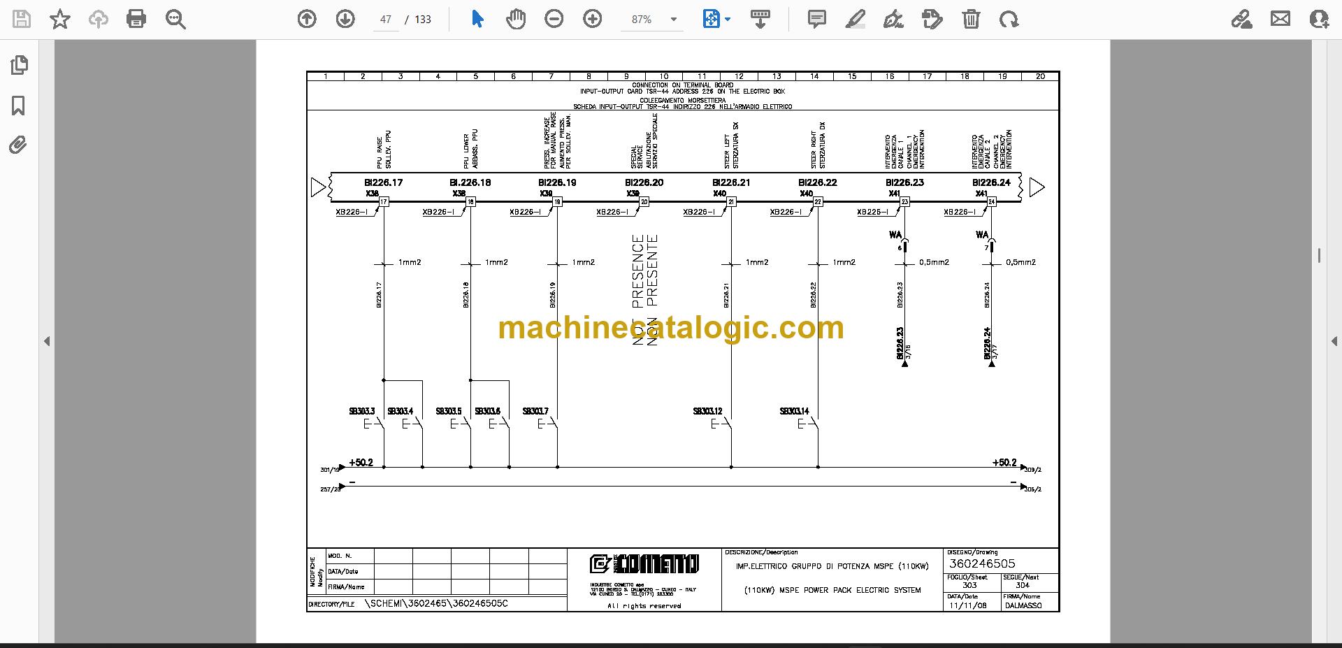
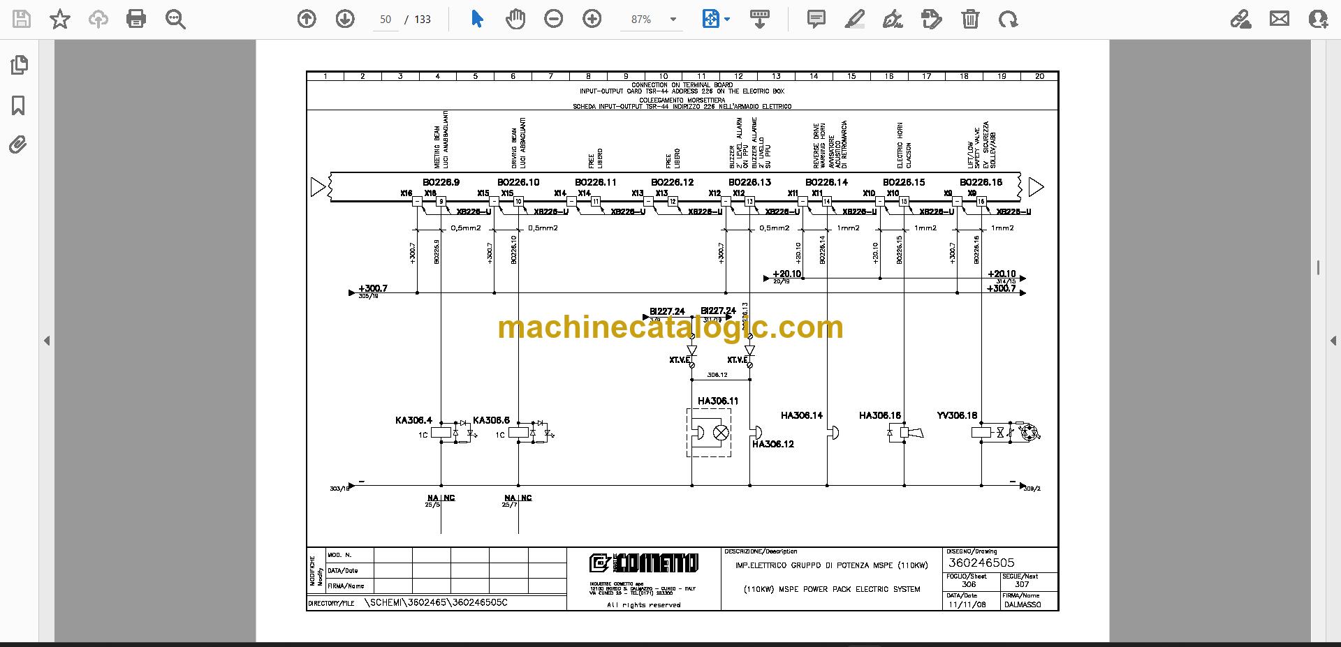
- Locate connections on the electric box, the EBI panel, the PPU and the cabin, including the coupling connector and terminal board.
- Identify the analogic input-output card TSR-52 (address 229) and the OL pressure switch, level switch and water tank sensors in the component list.
Who this is for
An electrician or field service technician who chases faults on heavy-haul transporters will use these sheets most. A workshop manager at a heavy transport company can also keep the set on file before a power pack goes back to work.
FAQ
Q: What do I receive and how is it organised?
A: You get 1 PDF file of 133 pages, in English and Italian. It holds electrical wiring sheets and hydraulic drawings, with component lists naming the parts on the sheets.
Q: Which machine does it fit?
A: It is for the Cometto MSPE Power Pack 110 kW, publication number 360246505. The title wording is "MSPE 110 kW Power Pack Electrical System".
Q: How does it fit my job?
A: If you're tracing a fault, replacing a control box, harness or sensor, or working on a unit that arrived without its drawings, the wire routes and the box layouts (including EB2) are where you'll look first.
Keep it on the workshop server and the next time a power pack stops, you can open the right sheet in seconds.
Click here to view the preview (PDF)
📘 Show Index
Table of Contents:
- General supply
- Alternator
- Emergency system supply
- Reset start
- Emergency relay
- Emergency stop
- Override
- Engine stop control
- Emergency stop circuit
- Remote emergency
- Connectors
- Engine remote stop control
- General key
- Power supply command
- Supply under-key
- Supply command supply
- Starting motor
- For indicator
- Starter heater
- Heater W.L
- From emergency key
- Electronic box
- Diagnostic (X200)
- Warning light
- Emergency key
- Emergency control
- Control motor
- FOG light supply
- Reverse drive warning horn and light
- And electric horn supply
- Emergency remote control
- Power supply
- Side-marker
- Lights side left
- Lights side right
- Light rear side
- Light vehicle side
- Socket on
- The EBL box
- On the EBI panel
- Electric box
- Fuel tank
- Working light
- Electric box side
- Command lights
- LOW pressure engine
- OL pressure switch
- Height temperature head
- Desel engine temperature switch
- Minimum level fuel
- Level switch
- Height temperature
- Clogging filter
- Alarm
- Water tank
- Electronic display
- Display electronic
- Control motor desel
- On the PPU
- Selector switch
- For emergency
- Service
- On the cabin A
- Vehicle coupling
- Right side
- Vehicle coupung connector
- Coupling connector
- Local bus connector
- Remote control
- Connector local bus
- Connection on terminal board
- Input-output card TSR-44 address 226 on the electric box
- Input-output card TSR-44 address 227 on the electric box
- Analogic input – output card TSR-52 address 228 on the electric box
- Analogic input – output card TSR-52 address 229 on the electric box
- Analogic input – output card TSR-52 address 230 on the electric box
- PPU electric installation review
- Front
- Cable lamp layout (ebi)
- EBI box layout
- Door box component layout 4310334
- Connection push-button
- And warning lights
- For push
- Button panel
- EB2 box layout
- EB3 box layout
- Terminal strip in the electric box EB3 (XTE2)
- Vehicle power supply
- Electric box connection
Cometto PDF Manuals
All Crane Manuals