Develon DL380-7 Wheel Loader Shop Manual (950106-02249) (10001 and Up)
Out on a quarry floor or in a muddy yard, the DL380-7 is doing heavy loading all day—face rock, trucks, stockpiles, the ugly jobs. This shop manual is what you use when you’re past quick checks and need to tear deep into the machine without guessing. It helps you plan the teardown, trace faults, and then reassemble so you don’t end up with a mystery rattle or a dead hydraulic circuit. Say you’ve got weak lift after a hose blowout and filter change didn’t fix it—this is what you’ll use to isolate the fault, strip the valve stack, inspect the guts, then torque and bleed it right.
Applications & Use Cases
- Plan a full axle or differential teardown, lay out the workspace, and route parts so you don’t mix shims or bearings between sides.
- Trace a driveline vibration, inspect U-joints and flanges, then follow the general torque sequence so everything lines up true on reassembly.
- Check loader linkage wear, replace pins and bushings, and verify alignment so the bucket tracks straight and doesn’t bind under load.
- Isolate hydraulic issues, test individual sections, then bleed and verify each function after you’ve had lines and cylinders apart.
- Strip the cooling pack, inspect seals and mounts, then reassemble so airflow paths are clear and hoses aren’t rubbing through.
FAQ
Q: Is this a PDF I can search on my laptop or phone, or just a scanned picture?
A: It’s typically a searchable PDF, so you can jump to systems and terms, though some diagrams are just images you’ll zoom in on.
Q: Can I print only the sections I need and take them to the jobsite?
A: Yes, most folks print the teardown and torque pages, stick them in a plastic sleeve, and keep the laptop out of the dust.
Safety Note
Always support the loader arms and machine properly before you crawl under it or crack any pressurized lines.
Develon DL380-7 Wheel Loader Index:
- DL380-7
- Revision
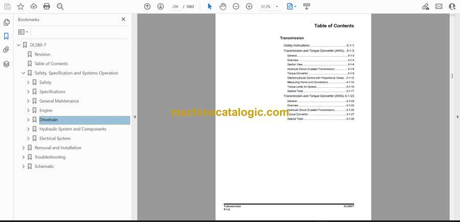
- Table of Contents
- Safety, Specification and Systems Operation
- Safety
- Wheel Loader Safety
- Safety Instructions
- General
- Transportation
- Operation
- Long Term Storage
- Maintenance
- Environment and Circumstances
- Specifications
- General Specifications
- Safety Instructions
- General
- Component Locations
- Working Range and Dimensions
- Working Capacities
- General Specifications
- Performance Tests
- Preparation for Performance Tests
- Operational Performance Standard Table
- Operational Performance Test
- Approximate Weight of Workload Materials
- Engine Specifications
- Safety Instructions
- Engine Specification
- Engine Performance Curves
- Tightening Torques
- Drivetrain Specifications
- Safety Instructions
- Specification
- Hydraulic Systems Specifications
- Safety Instructions
- Specification
- General Maintenance
- General Maintenance Instructions
- Safety Instructions
- Welding Precautions and Instructions
- Hydraulic System – General Precautions
- Maintenance Service and Repair Procedure
- Hydraulic System Cleanliness and Oil Leaks
- Cleaning and Inspection
- Hydraulic Pressure Checks
- Troubleshooting of Refrigerant System
- Refrigerant System Repairs
- Standard Torques
- Safety Instructions
- Torque Values for Standard Metric Fasteners
- Torque Values for Standard U.S. Fasteners
- Type 8 Phosphate Coated Hardware
- Torque Values for Hose Clamps
- ORFS Swivel Nut Recommended Torque
- Torque Values for Split Flanges
- Torque Wrench Extension Tools
- Engine
- Engine
- Safety Instructions
- General Information
- Mechanical System
- Fuel System
- Lubricating System
- Cooling System
- Intake/Exhaust System
- Engine Control System
- After Treatment System
- Drivetrain
- Transmission
- Safety Instructions
- Transmission and Torque Converter (4WG)
- Transmission and Torque Converter (5WG)
- Axle
- Safety Instructions
- Front Axle
- Rear Axle
- Driveshaft
- Safety Instructions
- General
- Hydraulic System and Components
- Steering
- Safety Instructions
- Power Steering System
- Steering Unit
- Steering Pump
- Flow Amplifier
- Jerk Softener and Accumulator
- Brake
- Safety Instructions
- Service Brake
- Brake and Pilot Supply Valve
- Parking Brake
- Brake Pedal Valve
- Accumulator
- Brake Filter
- Cooling System
- Safety Instructions
- Cooling System
- Fan and Brake Pump
- Fan Motor
- Radiator Assembly
- Hydraulic System
- Safety Instructions
- Main Pump
- Main Control Valve
- Pilot System
- Hydraulic System
- Oil Tank
- Electrical System
- Systems Operation and Description
- Safety Instructions
- Power System
- Starting System
- Charging System
- Gauge Panel system
- EPOS system
- Removal and Installation
- Removal and Installation
- Engine
- Safety Instructions
- Before Removing and Installing
- Engine and Transmission Assembly
- DEF (adblue®) Quality Sensor
- ECU (Engine Control Unit)
- Alternator
- Starter Motor
- Sensors – After Treatment
- V-Belt
- Hydraulic Systems and Structure
- Safety Instructions
- Before Removing and Installing
- Front Axle
- Rear Axle
- Drive Shaft
- Transmission Assembly
- Fuel Tank
- Joystick Valve (Work Lever)
- Cabin Assembly
- Undercovers
- Air Condenser Filter
- Electric and Electronic
- Safety Instructions
- Before Removing and Installing
- Gauge Panel
- Battery Assembly
- Cabin Switches
- Cabin Photo Sensor
- DC-DC Controller
- Display Monitor
- EPOS Controller
- TCU Controller
- ACU Controller
- Microphone Controller
- Smart Key Controller
- TMS Controller
- Wiper Motor
- Combination Switch
- Transmission Lever
- Troubleshooting
- Wiring Harness Layout
- Safety Instructions
- Wiring Device
- Wiring Harness Layout
- Front Harness
- Main Harness (1/2)
- Main Harness (2/2)
- Cabin Harness (1/2)
- Cabin Harness (2/2)
- Engine Harness
- Battery Harness
- Error Code
- Safety Instructions
- VCU Error Code
- 1. VCO001 Gauge Panel Communication
- 2. VCO002 E-ECU Communication
- 3. VCO003 TCU Communication
- 4. VCO004 Electric Steering Communication
- 5. VCO005 Keypad 1 Communication
- 6. VCO007 Cluster Communication
- 7. VCO008 Smart Key Controller Communication
- 8. VCO009 Combination Lever Communication
- 9. VCO010 Aircon Switch Panel Communication
- 10. VCO011 Aircon Unit Communication
- 11. VCO012 ACU Communication
- 12. VCO013 Electric Joystick Communication
- 13. VPV001 Cooling Fan Proportional Valve
- 14. VPV002 Electronic MCV Boom Up Proportional Valve
- 15. VPV003 Electronic MCV Boom Down Proportional Valve
- 16. VPV004 Electronic MCV Bucket Crowd Proportional Valve
- 17. VPV005 Electronic MCV Bucket Dump Proportional Valve
- 18. VPV006 3rd Spool Up Proportional Valve
- 19. VPV007 3rd Spool Down Proportional Valve
- 20. VAL001 Alternator Potential
- 21. VRY001 Right Turn Signal Lamp Relay
- 22. VRY002 Left Turn Signal Lamp Relay
- 23. VRY003 Emergency Steering Relay
- 24. VRY004 Horn Relay
- 25. VRY005 Rear Window Glass Heater Relay
- 26. VRY007 ACC Relay
- 27. VRY008 Auto Shut Off Relay
- 28. VSV001 Reverse Fan Solenoid Valve
- 29. VSV002 Brake Solenoid Valve
- 30. VSV003 Parking Brake Release Solenoid Valve
- 31. VSV005 Electric Steering Solenoid Valve
- 32. VSV006 LIS Solenoid Valve
- 33. VSV007 Quick Coupler Solenoid Valve
- 34. VGC001 Boom Magnet
- 35. VGC003 Power Mode Foot Switch
- 36. VGC004 Accelerator Pedal
- 37. VGC005 Head Lamp High Beam
- 38. VGC006 Head Lamp Low Beam
- 39. VGC007 Front Wiper Motor Speed I
- 40. VGC008 Front Wiper Motor Speed II
- 41. VGC009 Rear Wiper Motor
- 42. VGC010 Front Working Lamp
- 43. VGC011 Clearance Lamp
- 44. VGC012 Rear Work Lamp 1
- 45. VGC013 Rear Work Lamp 2
- 46. VGC014 Rear Window Washer Pump
- 47. VGC015 Front Window Washer Pump
- 48. VGC016 Rotating Beacon
- 49. VGC017 Mirror Heater
- 50. VGC018 Pilot Buzzer
- 51. VGC019 3rd Shift Lever
- 52. VGC023 Engine Running Signal
- 53. VSP001 Main Pump Pressure Sensor
- 54. VSP002 Steering Pump Pressure Sensor
- 55. VSP003 Brake Oil Pressure Sensor
- 56. VSP004 Fan Motor Pressure Sensor
- 57. VSP005 Boom Head Pressure Sensor
- 58. VSP006 Boom Rod Pressure Sensor
- 59. VSE001 Fuel Sensor
- 60. VSE002 Oil Temperature Sensor
- 61. VSE004 WIF Sensor
- 62. VS5001 Accelerator Pedal
- 63. VS5002 Brake Pedal (A)
- 64. VS5003 Brake Pedal (B)
- 65. VS5004 Boom Angle Sensor (A)
- 66. VS5005 Boom Angle Sensor (B)
- 67. VS5006 Bucket Angle Sensor (A)
- 68. VS5007 Bucket Angle Sensor (B)
- 69. VS5008 Electric Steering Joystick (A)
- 70. VS5009 Electric Steering Joystick (B)
- 71. VS5010 Thumbwheel Switch
- 72. VS5011 Machine Controller +5 V Output 1
- 73. VS5012 Machine Controller +5 V Output 2
- ECU Error Code
- TCU Error Code
- Electric Steering Error Code
- Schematic
- Hydraulic Schematic / Electrical Schematic
- Hydraulic Schematic
- Hydraulic Schematic (P-MCV)
- Hydraulic Schematic (E-MCV)
- Electrical Schematic
Develon


