Develon DX490LC-7 Crawler Excavator Shop Manual (950106-02204BE) (10001 and Up)
A DX490LC-7 usually lives in the rough stuff—quarries, big demo sites, heavy pipe work—where downtime costs real money. This shop manual helps you plan a full teardown, trace faults methodically, and then get everything back together without mystery bolts left on the cart. Say you’ve got a boom drift issue and metal in the filters; with this manual you can strip the cylinder, inspect the barrel and rod, verify clearances, then reassemble and bleed the system the right way the first time.
Applications & Use Cases
- Strip the upper structure, isolate swing issues, inspect the bearing and gear teeth, then follow the general torque sequence so the slew ring seats evenly.
- Plan your bench layout before a final drive teardown, route parts logically, and check each gear set and bearing while it’s on the table.
- Pull main control valves, trace internal leaks, test spools, then align and stack sections correctly so you don’t pinch an O-ring or miss a shim.
- Rebuild boom, arm, and bucket cylinders, verify seal orientation, and bleed the lines so you don’t chase spongy controls later.
- During engine or pump removal, mark hoses and harnesses, inspect mounts and couplers, then re-route and align everything cleanly on reassembly.
FAQ
Q: Is this a PDF I can search through, or just scanned pages?
A: It’s typically a searchable PDF, so you can jump to systems and trace procedures with keyword searches.
Q: Can I print just the sections I need to take to the machine?
A: Yes, most folks print the job-specific pages, stick them in plastic sleeves, and keep the full file on a laptop or tablet in the shop.
Safety Note
Always support the upper structure and attachments with rated stands or blocking before you crawl under or start loosening major pins or mounts.
Develon DX490LC-7 Crawler Excavator Index:
- DX490LC-7/DX530LC-7
- Revision
- Table of Contents
- Safety, Specification and Systems Operation
- Safety
- Track Excavator Maintenance Safety
- Safety Instructions
- Safety Messages
- General
- Long Term Storage
- Maintenance
- Environment and Circumstances
- Specifications
- General Specifications
- Safety Instructions
- General
- Component Locations
- Overall Dimensions
- Standard Specification
- Performance Tests
- Preparation for Performance Tests
- Operational Performance Standard Table
- Operational Performance Test
- Engine Specifications
- Safety Instructions
- Engine Performance Curves
- Tightening Torques
- Hydraulic Systems and Structure Specifications
- Safety Instructions
- Hydraulic System
- Swing Mechanism
- Travel System
- Under Carriage
- Structure
- General Maintenance
- General Maintenance Instructions
- Safety Instructions
- Welding Precautions and Instructions
- Hydraulic System – General Precautions
- Maintenance Service and Repair Procedure
- Hydraulic System Cleanliness and Oil Leaks
- Cleaning and Inspection
- Standard Torques
- Safety Instructions
- Torque Values for Standard Metric Fasteners
- Torque Values for Standard U.S. Fasteners
- Type 8 Phosphate Coated Hardware
- Torque Values for Hose Clamps
- ORFS Swivel Nut Recommended Torque
- Torque Values for Split Flanges
- Torque Wrench Extension Tools
- Engine
- Engine
- Safety Instructions
- General Information
- Mechanical System
- Fuel System
- Lubricating System
- Cooling System
- Intake and Exhaust System
- Engine Control and Electrical System
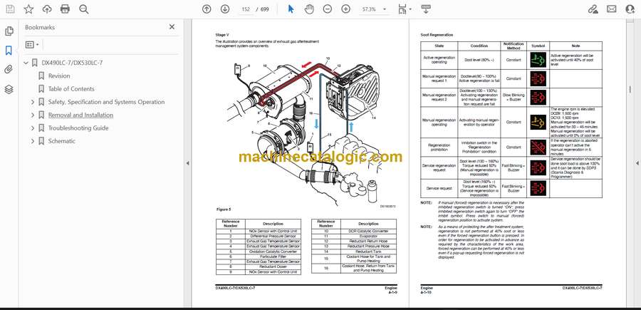
- After Treatment System
- Hydraulic System and Components
- Systems Operation, Description and Inspection
- Safety Instructions
- General
- Hydraulic Schematic
- Hydraulic Component
- Main Oil Circuit
- Pilot Oil Circuit
- Return and Drain Oil Circuit
- Main system operation
- Pilot System Operation
- Components Operation, Description and Inspection
- Safety Instructions
- Main Pump
- Main Control Valve
- Swing Device
- Fan Pump
- Fan Motor for Oil Cooler
- Fan Motor for Radiator
- Joystick Valve
- Travel Control Valve
- Solenoid Valve
- EPPR Valve (One or Two Way)
- Center Joint
- Travel Device
- Electrical System
- Systems Operation and Description
- Safety Instructions
- General Schematics
- Power Supply
- Starting System
- Charging System
- AVM System
- Gauge Panel System
- EPOS system
- Removal and Installation
- Removal and Installation
- Engine
- Safety Instructions
- Before Removing and Installing
- ECU (Engine Control Unit)
- V-Belt
- Alternator
- Starter Motor
- DEF (adblue®) Quality Sensor
- Sensors – After Treatment
- Engine Assembly
- DPF (Diesel Particulate Filter)
- Hydraulic Systems and Structure
- Safety Instructions
- Before Removing and Installing
- Main Pump
- Drive Coupling
- Undercovers
- Hydraulic Oil Tank
- Fuel Tank
- Swing Device
- Fan Pump
- Oil Cooler Fan Motor
- Joystick Valve (Work Lever)
- Travel Control Valve
- Center Joint
- Travel Device
- Main Control Valve
- Cabin
- Air Condenser Filter
- Electric and Electronic
- Safety Instructions
- Before Removing and Installing
- Battery Assembly
- EPOS Controller
- TMS Controller
- AVM Controller
- Microphone Controller
- Smart Key Controller
- Wiper Controller
- DC-DC Controller
- Cabin Photo Sensor
- Cabin Switches
- Around View Monitor
- Display Monitor
- Hour Meter
- Wiper Motor
- Troubleshooting Guide
- Troubleshooting
- Wiring Harness Layout
- Safety Instructions
- Wiring Device
- Error Code
- Safety Instructions
- EPOS Error Code
- Engine Error Code
- Schematic
- Hydraulic Schematic
- Electrical Schematic
Develon


