A Eaton Fuller heavy duty transmission carries engine torque to the driveline on cranes and other heavy machines, and it's used on XCMG machines. When one starts jumping out of gear, leaking at the output, or losing air shift function, the shop needs the repair procedures in hand. This service manual is what a technician reaches for when the machine is out of warranty and the transmission is coming apart in your own bay.
What this manual helps you do
- Follow the timing procedures when you reassemble the countershaft assemblies and set up the gear train.
- Disassemble the output shaft assembly and the countershaft assemblies, then assemble them again in the right order.
- Remove the input shaft assembly without main case disassembly, and install the input shaft and main drive gear.
- Replace the reverse switch, output yoke/companion flange, oil seal, or integral oil pump.
- Test the neutral switch and install air lines, push-to-connect fittings, the air filter/regulator and a slave valve.
Who this is for
A rental fleet mechanic or crane service technician who rebuilds transmissions in-house will get the most from it. Independent repair shops and plant maintenance crews working on XCMG machines will find the same procedures useful.
FAQ
Q: What do I receive and how is it organised?
A: You get 1 PDF file, 248 pages, in English, publication number TRSM-1500. The text can be searched and copied, and it includes warnings and precautions, lubrication specifications, power flow diagrams and a change control log.
Q: Which transmissions does it fit?
A: It covers the RT/O/X-1X715/1X915 and RTO-1X707LL/DLL/MLL models, plus 2 more, under the title Eaton Fuller Heavy Duty Transmission Service Manual.
Q: How does it fit my repair job?
A: A service manual like this usually gives you the removal, disassembly, assembly and adjustment steps in the order you'll work. Search for the part name, pull up the procedure, and keep it open at the bench.
Keep it on file for every unit in the fleet with one of these transmissions, so the next rebuild doesn't start with guesswork.
Click here to view the preview (PDF)
📘 Show Index
Table of Contents:
- Warnings and Precautions
- Transmission Overview
- Purpose and Scope of Manual
- Serial Tag Information and Model Nomenclature
- Lubrication Specifications
- Transmission Operation
- Tool Specifications
- Preventive Maintenance Inspection
- Power Flow Diagrams
- Air System Overview
- General Troubleshooting Chart
- Air System Troubleshooting
- Timing Procedures
- How to Disassemble Roadranger Valve A-4900
- How to Assemble Roadranger Valve A-4900
- How to Remove the Air Lines and Hoses
- How to Install the Air Lines and Hoses
- How to Remove Compression Type Fittings
- How to Install Compression Type Fittings
- How to Remove Push-To-Connect Type Fittings
- How to Install Push-To-Connect Type Fittings
- How to Remove Rubber 1/4" Air Hoses
- How to Install Rubber 1/4" Air Hoses
- How to Remove the Air Filter/Regulator
- How to Install the Air Filter/Regulator
- How to Remove a Roadranger Valve
- How to Install a Roadranger Valve
- How to Remove a Slave Valve
- How to Install a Slave Valve
- How to Remove the Gear Shift Lever/Remote Shift Control
- How to Install the Gear Shift Lever/Remote Shift Control
- How to Adjust the Remote Shift Control (LRC Type)
- Neutral Switch Operation and Testing
- How to Remove the Neutral Switch
- How to Install the Neutral Switch
- Reverse Switch Operation and Testing
- How to Remove the Reverse Switch
- How to Install the Reverse Switch
- How to Remove the Shift Bar Housing
- How to Install the Shift Bar Housing
- How to Remove the Oil Seal – Mechanical Speedometer
- How to Install the Oil Seal – Mechanical Speedometer
- How to Remove the Oil Seal – Magnetic Speedometer
- How to Install the Oil Seal – Magnetic Speedometer
- How to Remove the Output Yoke/Companion Flange
- How to Install the Output Yoke/Companion Flange
- How to Remove the Auxiliary Section in Chassis
- How to Install the Auxiliary Section in Chassis
- How to Remove the Combination Cylinder Assembly
- How to Install the Combination Cylinder Assembly
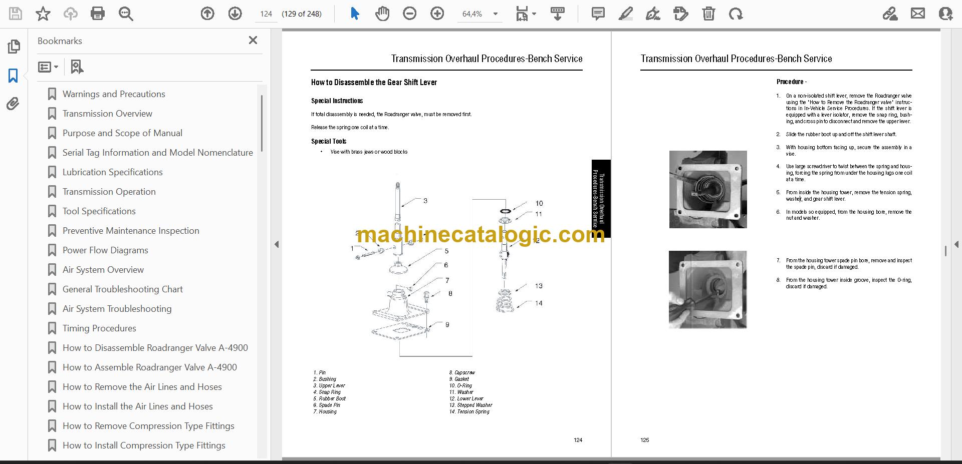
- How to Disassemble the Gear Shift Lever
- How to Assemble the Gear Shift Lever
- How to Disassemble the Standard Shift Bar Housing
- How to Assemble the Standard Shift Bar Housing
- How to Disassemble the Forward Shift Bar Housing
- How to Assemble the Forward Shift Bar Housing
- How to Remove the Input Shaft Assembly (without main case disassembly)
- How to Install the Input Shaft Assembly (without main case disassembly)
- How to Remove the Auxiliary Section with Tapered Bearings
- How to Remove the Auxiliary Countershaft Assembly
- How to Disassemble the Output Shaft Assembly
- How to Disassemble the Synchronizer Assembly
- How to Assemble the Synchronizer Assembly
- How to Assemble the Output Shaft Assembly
- How to Install the Auxiliary Countershaft Assembly
- How to Remove the Clutch Housing
- How to Remove the Auxiliary Drive Gear Assembly
- How to Disassemble the Upper Reverse Idler Gear Assembly
- How to Disassemble the Lower Reverse Idler Gear Assembly
- How to Remove the Upper and Lower Countershaft Bearings
- How to Remove the Mainshaft Assembly
- How to Remove the Countershaft Assemblies
- How to Disassemble the Countershaft Assemblies
- How to Remove the Input Shaft and Main Drive Gear
- How to Prepare the Main Case for Assembly
- How to Disassemble the Mainshaft Assembly
- How to Assemble the Countershaft Assemblies
- How to Assemble the Lower Reverse Idler Gear Assembly
- How to Install Countershaft Assemblies
- How to Install the Lower Countershaft Bearings
- How to Install the Input Shaft and Main Drive Gear
- How to Install the Mainshaft Assembly
- How to Install the Upper Countershaft Bearings
- How to Assemble the Upper Reverse Idler Gear Assembly
- How to Install the Auxiliary Drive Gear Assembly
- How to Install the Clutch Housing
- How to Disassemble the Integral Oil Pump without Auxiliary Oil Tube
- How to Assemble the Integral Oil Pump without Auxiliary Oil Tube
- How to Remove the Integral Oil Pump
- How to Install the Integral Oil Pump
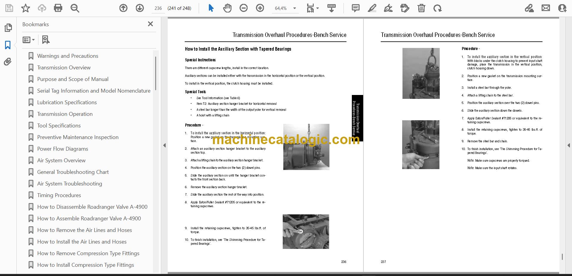
- How to Install the Auxiliary Section with Tapered Bearings
- Shim Procedure without a Shim Tool for Tapered Bearings
- Change Control Log
Eaton PDF Manuals
All Crane Manuals