$ 0
0
$ 0
0

Grove RT890E Rough Terrain Crane Full Manual (Operator, Parts, Service, Schematics)

Format: PDF (Printable Document)

File Language: English

File Pages: 4,270

File Size: 1003.45 MB (Speed Download Link)

File Count: 201 files (112 PDF)

Brand: Grove

Model: RT890E

Equipment Type: Rough Terrain Crane

Manuals Included: Operator Manual (556 pages), Parts Manual (2,059 pages), Service Manual (1,394 pages), Schematics (6 files), Load charts (2 files), Technical data (3 files), Component manuals (3 files), CDs and software (171 files)

Publication No.: Operator Manual: CTRL307-05, CTRL0068-02, CTRL068-04; Service Manual: CTRL069-04, CTRL069-01, CTRL308-04

Serial No.: 233324, 228778

Type of Document: Full Manual Set

Searchable: Partly, some files are scanned pages without a text layer

Delivery: Instant download after payment

Categories: ,

$ 100

Share:

Grove RT890E Rough Terrain Crane Full Manual (Operator, Parts, Service, Schematics)

Grove's RT890E is a single-cab rough terrain crane with a telescopic boom and outriggers, built to lift on uneven job sites where a truck crane can't get in. This full manual set is for the workshop that takes on a used RT890E that arrived without any paperwork and needs the whole machine documented before it goes back to work. Everything sits in one download, so the operator, the mechanic and the parts desk all work from the same source.

What this manual set helps you do

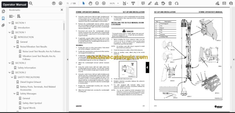
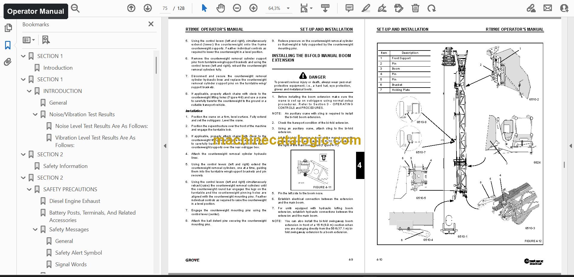
  • Operate the crane safely by following the operator manual on controls, set-up and installation, lubrication and the maintenance checklist.
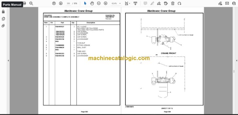
  • Order the right components from the parts manual, which has the parts catalog for the boom assembly, the LMI boom kit and the other assembly groups.
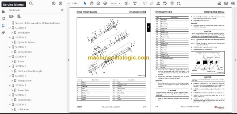
  • Repair and troubleshoot with the service manual, which runs through eight sections of repair and adjustment procedures.
  • Trace hydraulic and electrical circuits using the schematics.
  • Plan lifts with the load charts and check the technical data before a job.

Who this is for

A workshop or service company taking in a used RT890E gets the full documentation in one go: repair procedures for the mechanics, part references for the counter. A rental fleet manager can use it to give operators, technicians and the parts desk the same documents for each machine.

FAQ

Q: What do I receive and how is it organised?

A: You get 201 files, 112 of them PDF, with 4,270 PDF pages in total, all in English. The operator manual is 556 pages in 4 files, the parts catalog is 2,059 pages in 2 files, and the service manual is 1,394 pages in 4 files. Schematics, load charts, technical data, component manuals, CDs and software, and other documents come with them.

Q: Which machine does it fit?

A: It is the Grove RT890E rough terrain crane. The manuals are titled RT890E Operator Manual, RT890E Parts Catalog and RT890E Service Manual, so you can match them to your machine by model.

Q: How does it fit a crane that came without paperwork?

A: It gives you the daily checks, lubrication points, repair procedures and parts references in one place. You can start inspecting, servicing and ordering parts straight away.

Put every document for the RT890E in the hands of your operators, mechanics and parts desk with a single download.

📘 Show Index

Table of Contents:

Operator Manual Table of Contents

556 pages, 4 files

  • Publication CTRL307-05 (166 pages)
    • Front Matter
    • Section 1: Introduction
    • Section 2: Safety Precautions
    • Section 3: Operating Controls and Procedures
    • Section 4: Set-up and Installation
    • Section 5: Lubrication
    • Section 6: Maintenance Checklist
  • Publication CTRL0068-02 (128 pages)

    Same chapters as the edition above (another edition or language of this manual).

  • Publication CTRL068-04 (132 pages)
    • Section 1 INTRODUCTION
      • General
      • Noise/Vibration Test Results
    • Section 2 SAFETY PRECAUTIONS
      • Diesel Engine Exhaust
      • Battery Posts, Terminals, And Related Accessories
      • Safety Messages
    • Section 3. OPERATING CONTROLS AND PROCEDURES
      • Controls And Indicators
      • Operating Procedures
    • Section 4 SET-UP AND INSTALLATION
      • General
      • Installing Cable On The Hoist
      • Cable Reeving
    • Section 5. LUBRICATION
      • General
      • Lubrication Points
      • Hydraulic Lubrication
    • Section 6. MAINTENANCE CHECKLIST
      • General
      • Instructions
  • Manual 4 (130 pages)

    Same chapters as the edition above (another edition or language of this manual).
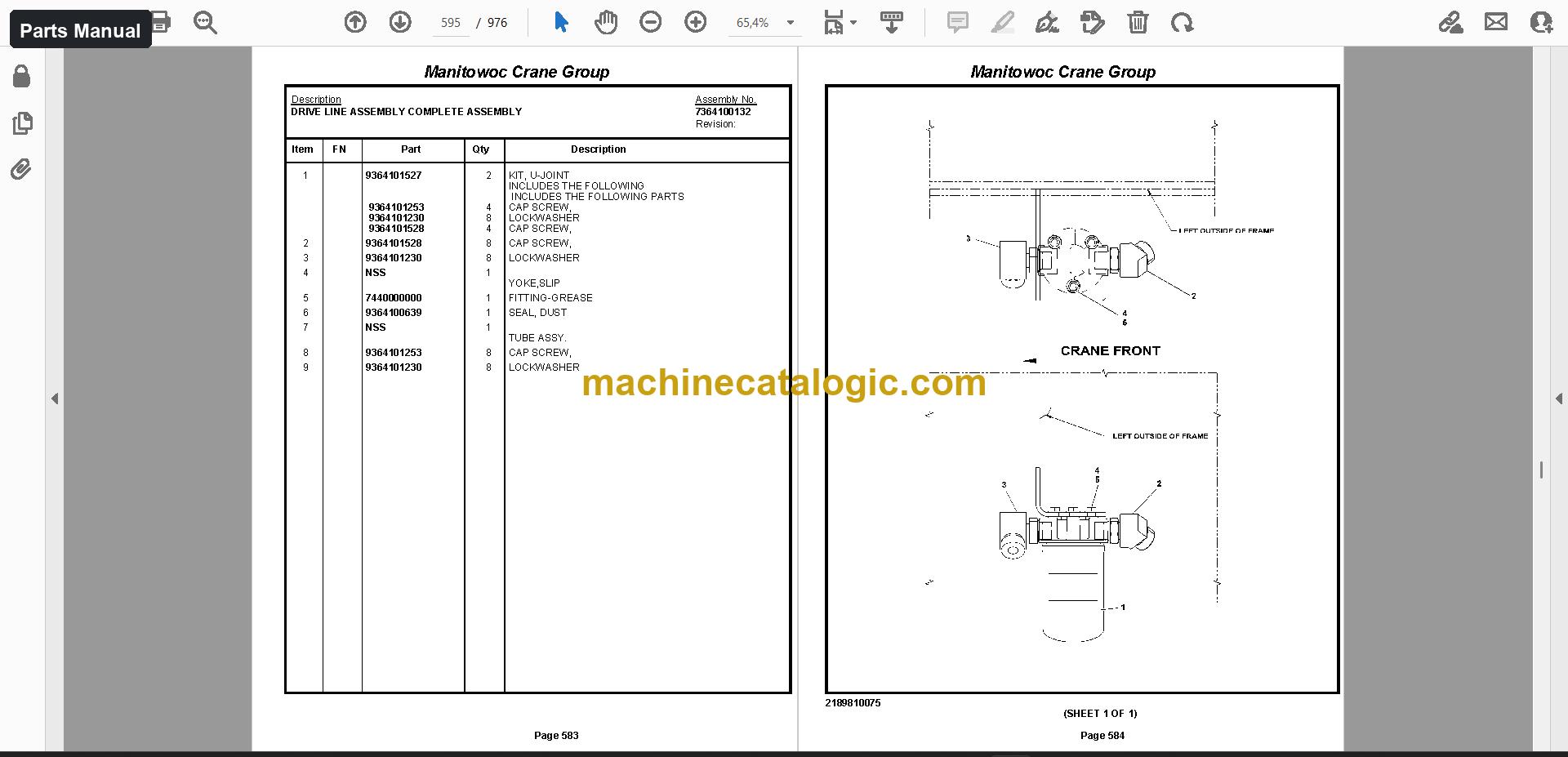
Parts Manual Table of Contents

2,059 pages, 2 files

  • Serial No. 233324 (1,083 pages)
    • BOOM ASSEMBLY
    • (SINGLE STAGE)
    • (COMPLETE ASSEMBLY)
    • EXTENSION INSTALL-FOLDING OFFSET BOOM
    • WEIGHT AND CHAIN ASSEMBLY
    • AUX BOOM NOSE INSTALLATION
    • BALL ASSEMBLY – OVERHAUL
    • TON SWIVEL
    • BOOM LIGHTS INSTALLATION
    • BOOM LIGHT SWITCH INSTALLATION-12V
    • SOCKET, 3/4'' OPEN WEDGE
    • LMI BOOM KIT (BCS)
    • COND
    • RETAINER
    • KIT INSTALLATION – LMI BOOM
    • LMI AUX NOSE KIT
    • KIT INSTALLATION – AUXILIARY NOSE LMI
    • HOOK BLOCK ASSEMBLY – 90 TON
    • SHEAVE
    • KIT – LMI BI-FOLD JIB BOOM EXTENSION
    • KIT INSTALL – LMI BI-FOLD JIB EXTENSION
    • CARRIER INSTALLATION – BOOM EXTENSION
    • POLE INSTALLATION-JIB RELEASE
    • TURNTABLE DRIVE
    • HYDRAULIC,WATER,ELECTRIC & AC
    • HOSE REEL INSTALLATION
    • ELECTRICAL SYSTEM INSTALLATION
    • VALVE INSTALLATION-SS
    • BOLT INSTALLATION – BEARING
    • MAIN HOIST INSTALLATION
    • MIRROR INSTALLATION – HOIST
    • BINDER INSTALLATION
    • CYLINDER INSTALLATION
    • SWING LOCK INSTALLATION
    • VALVE COVER COMPS INSTALLATION
    • TURNTABLE LOCK PIN INSTALLATION
    • HYDRAULIC LINES INSTALLATION
    • LIFT CYLINDER & LOWER PIN INSTALLATION
    • WASHER BOTTLE INSTALLATION
    • BEACON LIGHT INSTALLATION
    • CRANE STAR INSTALLATION-SUPERSTRUCTURE
    • FLY-BACK DIODE-MODIFIED
  • Serial No. 228778 (976 pages)
    • BOOM ASSEMBLY – 5 SECTION
    • (DUAL STAGE)
    • (SINGLE STAGE)
    • COMPLETE ASSEMBLY
    • WEIGHT AND CHAIN ASSEMBLY
    • EXTENSION INSTALL-FOLDING OFFSET BOOM
    • EXTENSION ASSY – FOLDING OFFSETABLE BOOM
    • NOSE INSTALLATION – AUXILIARY BOOM
    • BALL ASSEMBLY – OVERHAUL
    • TON SWIVEL
    • SOCKET, 3/4’’ OPEN WEDGE
    • LIGHTS INSTALLATION – BOOM
    • (NOT AVAILABLE AS ASSEMBLY)
    • LMI BOOM KIT (BCS)
    • COND
    • RETAINER
    • KIT INSTALLATION – LMI BOOM
    • HOOK BLOCK ASSEMBLY – 90 TON
    • SHEAVE
    • LMI AUX NOSE KIT
    • KIT INSTALLATION – AUXILIARY NOSE LMI
    • KIT – LMI BI-FOLD JIB BOOM EXTENSION
    • DUMMY PLUG, 2-PIN
    • KIT INSTALL – LMI BI-FOLD JIB EXTENSION
    • CARRIER INSTALLATION – BOOM EXTENSION
    • CAB INSTALLATION

Service Manual Table of Contents

1,394 pages, 4 files

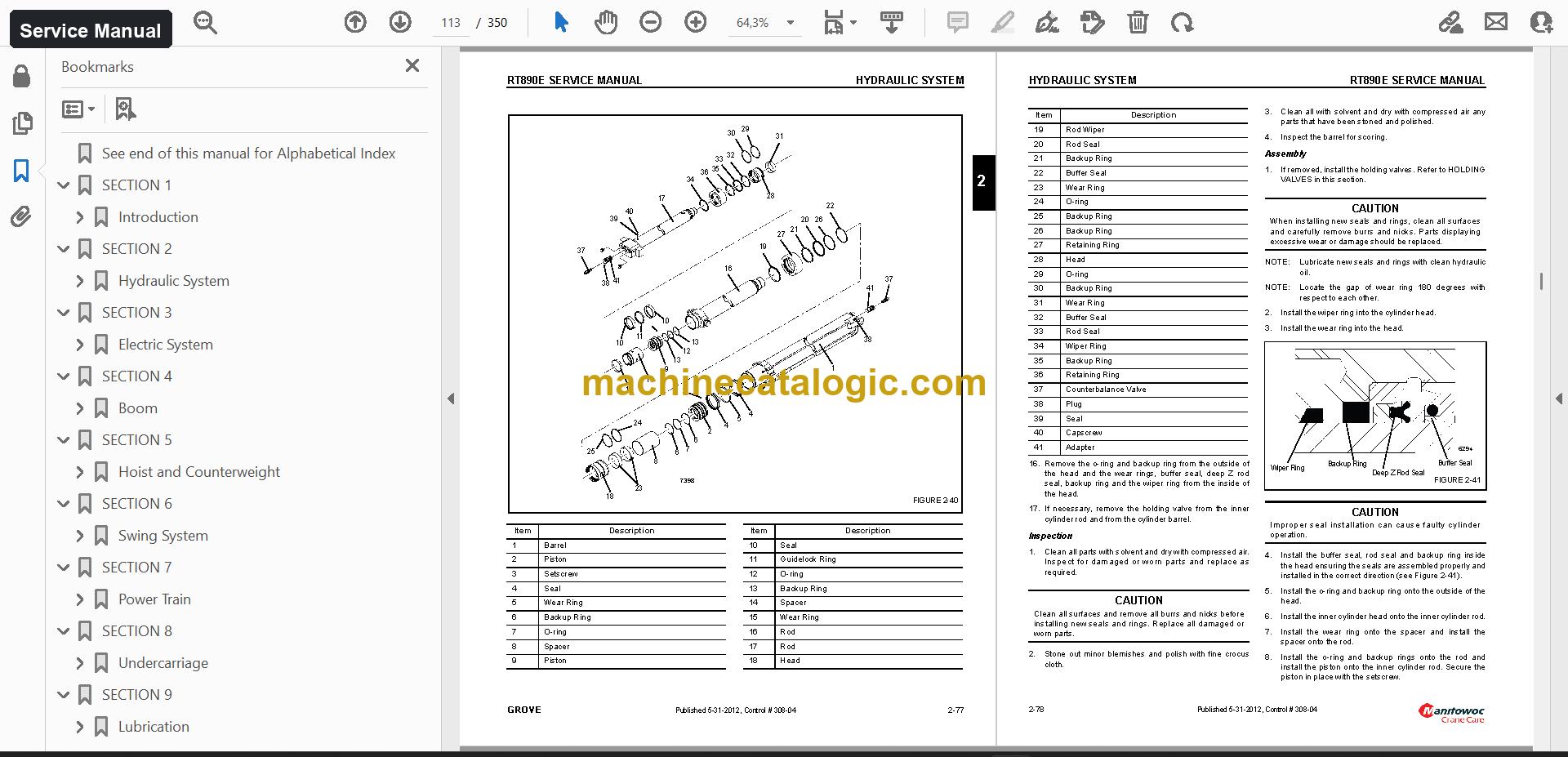
  • Publication CTRL069-04 (350 pages)
    • Description
    • List of Specifications
    • General
    • Dimensions
    • Capacities
    • Torque Converter/Transmission
    • Engine
    • Axles
    • Brakes
    • Wheels and Tires
    • Swing Gearbox
    • Boom
    • Swivel Assembly
    • Hydraulic Pumps
    • General Maintenance
    • Cleanliness
    • Removal and Installation
    • Disassembly and Assembly
    • Pressing Parts
    • Locks
    • Wires and Cables
    • Shims
    • Bearings
    • Gaskets
    • Batteries
    • Hydraulic Systems
    • Fatigue of Welded Structures
    • Loctite
    • Fasteners and Torque Values
    • Wire Rope
    • Environmental Conditions
    • Dynamic Shock Loads
    • Lubrication
    • Precautions and Recommendations During Inspection or Replacement
    • Wire Rope Inspection (Running Ropes and Pendant Cables)
    • Wire Rope Inspection (Boom Extension and Retraction Cables)
    • Wire Rope Replacement (All Wire Rope)
    • Seizing Wire Rope
    • Installing FLEX-X 35 Wire Rope
    • Procedures for Cutting and Preparing FLEX-X 35
    • Theory Of Operation
    • Maintenance
    • Hydraulic Oil Recommendations
    • Draining and Flushing
    • Removing Air from the Hydraulic System
    • Parts Replacement
    • Directional Control Valves
    • Supply Pressure and Return Circuit
    • Oil Cooler
    • Pressure Setting Procedures
    • Boom Lift and Telescope(s) Pressures
    • Procedure B – For Setting The Outrigger Pressures
    • Procedure C – For Setting The Oil Cooler Motor Pressure
    • Procedure D – For Checking/Setting The Load Sense Reduction Manifold
    • Charging Valve Charging Limits
    • Procedure F – For Checking Accumulator Pre-Charge Pressure
    • Procedure G – For Pre-Charging The Accumulator
    • Procedure H – For Checking/Setting The Front Steer Pressure
    • Procedure I – For Checking/Setting The Swing Work Port Pressure
    • Procedure J – For Checking/Setting The Swing Brake Release Pressure
    • Procedure K – For Checking/Setting The Controller Supply Pressure
    • Procedure L – For Checking/Setting The Hose Reel Brake and Motor Supply
    • Cylinder Extend Pressure
    • Tilt Cylinder Extend/Retract Pressure
    • Procedure P – For Checking/Setting The Luffing Jib Lower Pressure
    • Valves
    • Front Steer, Swing and Accessory Manifold
    • Steering Control Valve
    • Hydraulic Remote Control Valve
    • Swing Power Brake Valve With Treadle Pedal
    • Speed Swing Valve
    • Cab Tilt Double Pilot Operated Check Valve
    • Tandem Brake Valve with Treadle Pedal
    • Dual Accumulator Charge Valve
    • Hydraulic Accumulator Service Brake
    • Holding Valves
    • Cross Axle Differential Lock Valve
    • Outrigger Control Manifold
    • Pilot Operated Check Valve
    • Axle Lockout, Rear Steer and Oil Cooler Fan Motor Control Manifold
    • Check Valves
    • Hi-Low Range, Axle Disconnect and Parking Brake Valve
    • Load Sense Reduction Manifold
    • Cylinders
    • Surface Protection for Cylinder Rods
    • Lift Cylinder
    • Dual Rod Telescope Cylinder
    • Upper Telescope Cylinder
    • Axle Oscillation Lockout Cylinder
    • Steer Cylinder
    • Outrigger Extension Cylinder
    • Outrigger Stabilizer Cylinder
    • Cab Tilt Cylinder
    • Counterweight Removal Cylinder
    • Counterweight Pin Cylinder
    • Park Brake Cylinder
    • Alternator
    • Relay Panel And Fuse Panel
    • Relays
    • General Troubleshooting
    • Troubleshooting Swivel-Caused Electrical Problems
    • Connector Troubleshooting
    • Control Module Diagnostic Light
    • Alternator Replacement
    • Starter Replacement
    • Battery Replacement
    • Relay Panel Component Replacement
    • Instrument Replacement
    • Switch Replacement
    • Windshield Wiper Assembly Replacement
    • Windshield Washer Assembly Replacement
    • Skylight Wiper Assembly Replacement
    • Troubleshooting
    • Optional Equipment
    • Strobe Light
    • Spotlight
    • Boom Mounted Floodlights
    • Rear View Mirror
    • Air Conditioner
    • Lattice Extension
    • Optional Lattice Extension
    • Optional Lattice Extension Inserts
    • Boom Control Switches
    • Boom Auto/Manual Telescope Mode Switches
    • Center Mid/Inner Mid Boom Telescope Sections Select Switch
    • Boom Extension
    • Boom Retraction
    • LMI System (With Boom Control System)
    • Telescoping Control System Description
    • Extension Sequence for the Main Boom (Figure 4-1)
    • Extension Sequence for the Main Boom with Boom Extensions or Offset Jibs
    • Electronic Control System
    • Removal
    • Boom Disassembly
    • Boom Nose Sheaves
    • Boom Assembly
    • Installation
    • Functional Check
    • Inspection
    • Boom Alignment And Servicing
    • Cam Operated Check Valve Adjustment
    • Guide Block Adjustment
    • Boom Extension And Retraction Cable
    • Adjustment
    • Telescope Circuit
    • Hose Reel
    • Lift Circuit
    • Auxiliary Boom Nose
    • Counterweight and Auxiliary Hoist
    • Counterweight Without Auxiliary Hoist
    • Installing the Bi-Fold Manual Boom Extension
    • Checking the Transport Condition
    • Erecting Procedure
    • Stowing Procedure
    • Hose Drum for Hydraulic Luffing Boom Extension
    • Raising and Lowering the Hydraulic Boom Extension
    • Transportation on a Separate Vehicle
    • Connecting and Disconnecting the Hydraulic Boom Extension
    • Hydraulic Connection at the Boom Extension
    • Lifting Limit Switch on the Lattice Extension
    • Folding Out/In the Deflection Sheaves on the 33 ft (10.1 m) Section
    • Positioning/Remove the Hoist Cable
    • Setting the Folding Swingaway Extension Offset (Figure 4-75)
    • Removing the Bi-Fold Manual Boom Extension
    • Installing/Removing 16 ft (4.9 m) Sections
    • Installing the 16 ft (4.9 m) Sections
    • Removing the 16 ft (4.9 m) Sections
    • Boom Extension (Additional Equipment)
    • Identification and Slinging Points
    • Assembly Of Boom Extensions (Figure 4-80)
    • Electrical Connection at the Boom Extension
    • Unfolding/Folding the Deflection Sheave on the 16 ft (4.9 m) Section
    • Positioning/Removing the Hoist Cable
    • Extension and/or Inserts Erected
    • Adjustment Procedure for Stowage Brackets for Hydraulic Luffing Jib
    • Auxiliary Single-Sheave Boom Nose (Additional Equipment)
    • Identification
    • Installing/Removing Auxiliary Single-Sheave Boom Nose
    • Removing the Auxiliary Single-Sheave Boom Nose
    • Rigging The Auxiliary Single-Sheave Boom Nose
    • Rigging in Transport Position
    • Rigging in Working Position
    • Attaching and Removing Hoist Cable
    • Possible Reeving Methods on the Auxiliary Single-Sheave Boom Nose
    • Lifting Limit Switch
    • Raising And Setting Down The Main Boom With Rigged Lattice Extension
    • Telescoping With Rigged Lattice Extension
    • Operating With The Lattice Extension
    • Procedure if the Permissible Wind Speed is Exceeded
    • Monthly Maintenance Work
    • Warm-up Procedure
    • Servicing
    • Hoist to Boom Alignment
    • Preparation
    • Tools Required
    • Procedure
    • Piston Motor and Control Valve
    • Idler Drum and Cable Follower
    • Hoist Drum Rotation Indicator System
    • Counterweight Removal
    • Removal of Standard Counterweight and Auxiliary Hoist
    • Removal of Counterweight Without Auxiliary Hoist
    • Installation of Counterweight Without Auxiliary Hoist
    • Third Wrap Indicator (Optional)
    • Introduction
    • Swing Motor
    • Swing Gearbox And Brake
    • Swing Bearing
    • Swivels
    • Hydraulic Swivel
    • Two Port Water Swivel
    • Electrical Swivel
    • Engine Control System Switches and Indicator Lights
    • Fuel System
    • Air Intake System
    • Water Cooling System
    • Test Equipment
    • Antifreeze/Coolant
    • Radiator Removal and Installation
    • Drive Train
    • Transmission/Torque Converter
    • Towing or Pushing
    • Servicing the Crane After Transmission/Torque Converter Overhaul
    • Engine Block Heater
    • Steering Systems
    • Rear Steering System
    • Front Steering Control Valve
    • Rear Steer/ Axle Lockout/Fan Drive Valve
    • Steer Cylinders
    • Rear Axle Oscillation Lockout System
    • Axle Oscillation Lockout Cylinders
    • Axle Oscillation Lockout Valve
    • Brake System
    • Service Brakes
    • Corrosion Protection
    • Parking Brake Actuator
    • Parking Brake
    • Park Brake solenoid Valve
    • Outriggers
    • Outrigger Circuit
    • Outrigger Beam
    • Extension Cylinder
    • Stabilizer Cylinder
    • Outrigger Control Valves
    • Pintle Hook
    • Arctic Conditions – Below -18°C (0°F)
    • Arctic Conditions Down To -40°F
    • Lubrication Points
    • Wire Rope Lubrication
    • Cummins QSB6.7
    • Hoists
    • Antifriction Bearings
    • Double Row, Tapered Roller
    • Heating Bearings
    • Preload
    • Sleeve Bearings
    • Keep the System Clean
    • Sealing Elements
    • Hydraulic Lines
    • Application of Medium Strength Loctite
    • Frequent Inspection
    • Periodic Inspection
    • Method 1
    • Method 2
  • Publication CTRL069-01 (346 pages)
    • Section 1: Introduction
    • Section 2: Hydraulic System
    • Section 3: Electric System
    • Section 4: Boom
    • Section 5: Hoist And Counterweight
    • Section 6: Swing SYSTEM
    • Section 7: Power Train
    • Section 8: UnderCarriage
    • Section 9: Lubrication
  • Publication CTRL308-04 (350 pages)

    Same chapters as the edition above (another edition or language of this manual).
  • Manual 4 (348 pages)

    Same chapters as the edition above (another edition or language of this manual).

Also in this set

  • Schematics (6 files, 28 pages)
  • Load charts (2 files, 48 pages)
  • Technical data (3 files, 45 pages)
  • Component manuals (3 files, 137 pages)
    • PAT
  • CDs and software (171 files)
    • GROVE RT890E
    • RT890E
  • Other documents (6 files, 3 pages)

Grove PDF Manuals

All Crane Manuals

Related Manuals

0
0
Your Cart
Your cart is emptyReturn to Shop