Format: PDF (Printable Document)
File Language: English
File Pages: 595
File Size: 148.73 MB (Speed Download Link)
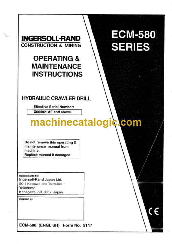
Brand: Ingersoll Rand
Model: ECM580 Series Hydraulic Crawler Drill
No: X004021AE and Above
Type of Document: Operating and Maintenance Manual
$ 59
General i-1
Procedures when receiving the machine —————— i-2
Machine identification plate location i-3
Engine identification plate location i-3
Instruction manual storage location i-4
Emergency exit location i-4
Fire extinguisher location i-4
General information i-5
Machine description 1-5
Engine installation i-6
Main frame installation i-6
Drill guide installation i-6
Controls and instruments installation i-6
Tramming system i-6
Steering system i-6
Braking system i-6
Emergency stop system i-7
Operator’s cab installation i-7
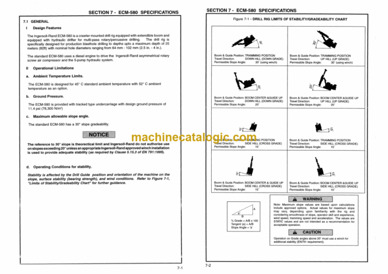
Gradeability i-7
Serviceability i-7
Standard features i-8
Main Assemblies i-8
SECTION 1 -SAFETY INFORMATION
1.1 Overview ___________________________ 1-3
1 2 WARNINGS 1-3
1 3 General 1-3
1 .4 Selection and qualification of personnel 1-4
1.5 Organizational Measures 1-5
1.6 Pre-starting Inspection 1-5
1.7 Safety Instructions governing operation 1-6
I Starting 1-7
II Operating 1-7
Ill Stopping 1-7
VI Maintenance 1-8
Warning of special dangers 1-1 O
1 9 Transporting and towing – Recommissioning 1-1 O
Safety related decals 1-12
___________________________ 1-12
Table 1 – Safety decal identification __________________ 1-13
I. International safety decals with interpretations 1-16
II. U S.A and English language safety decals with interpretations 1-20
Hazardous substances precaution 1-26
SECTION 2 – SYMBOL IDENTIFICATION
Overview _____________________________ 2-1
International & Combined Symbols – Part 1 2-2
International & Combined Symbols – Part 1 · Interpretation 2-3
International & Combined Symbols – Part 2 ________________ 2-4
International & Combined Symbols – Part 2 : Interpretation 2-5
International & Combined Symbols – Part 3 2-6
International & Combined Symbols – Part 3 · Interpretation 2-7
SECTION 3 – CONTROLS AND INSTRUMENTS
General 3-1
A – Operator’s Cabin located controls and instruments 3-1
B – Engine Compartment located controls and instruments 3-1
3.1 Flushing Air Pressure Gauge 3-4
3.2 Feed Hydraulic Pressure Gauge 3-4
3 3 Rotation Hydraulic Pressure Gauge 3-4
3.4 Drifter percussion Hydraulic Pressure Gauge 3-4
3.5 Drilling Angle Indicator Switch 3-4
3.6 Front Working Lights Switch (6, Figure 3-3) (ON/OFF) 3-4
3 7 Rear Working Lights Switch (7, Figure 3-3) (ON/OFF) 3-4
3.8 Window Wiper Switch (8, Figure 3-3) ON/OFF – Front Window 3-4
3 9 Roof Window Wiper Switch (9, Figure 3-3) ON/OFF 3-4
3.10 Window Washer Switch (10, Figure 3-3) ON/OFF 3-5
3.11 Drill Feed pressure adjuster Valve (11, Figure 3-3) 3-5
3.12 Engine emergency stop button 3-5
3 13 Centralizer & Slide Hood Control Lever 3-6
3 14 Mode Selector switch – (Dust Collector + full Flushing air) or (Low Flushing air +
Dust Collector) or (full Flushing Air only} or (automatic rod changer Control) __ 3-6
3.15 Automatic rod changer Clamp Control Lever 3-7
316 Automatic rod changer Arm Extension/Retraction and Arm Swing Control Lever_3-7
3 17 Auto Grease Switch (ON/OFF) 3-7
3 18 Coupling Retainer Control Button Switch 3-7
3 19 Drifter percussion control lever 3-8
3 20 drifter Rotation Control Lever (CCW I CW) 3-8
19/20 Percussion and rotation combined operation 3-9
3 21 Drill Feed Control Lever 3-1 O
3.22 Fast Feed button switch 3-1 O
3.23 Oscillation control Lever 3-11
3.24 Boom Extension Lever 3-11
3.25 Boom lift Lever 3-11
3.26 Boom Swing Lever 3-11
3 27 Guide Dump Lever 3-11
3.28 Guide Swing Lever 3-11
3.29 Guide Extension Lever 3-12
3.30 Left track tramming control lever 3-12
3 31 Right track tramming control lever 3-12
3.32 Oscillation Lock lever 3-13
3.33 Compressor “START/RUN” Valve 3-13
3 34 Tramming Lock Lever 3-13
3.35 Low Engine Oil Pressure Warning Indicator Light 3-14
3.36 Engine Coolant Temperature Warning Light 3-14
3.37 Compressor High Discharge Air Temperature Warning Light 3-14
3.38 Low Hydraulic Oil Level Warning Light (option) 3-14
3.39 Battery Charging rate Warning Light 3-15
3 40 Engine Air Cleaner Restriction Warning Light 3-15
ii
TABLE OF CONTENTS
Contents Page
3.41 Compressor Air Cleaner Restriction Warning Light ____________ 3-15
3.42 Low Fuel Level Warning Light 3-15
3 43 Engine Oil Pressure Gauge 3-15
3 44 Engine Coolant Temperature Gauge 3-16
3.45 Engine Tachometer 3-16
3 46 Engine Start-up Switch 3-16
3.47 Engine Preheater Indicator Light 3-17
3.48 Engine Speed Control Valve 3-17
3 49 Dust Collector Filter Cartridge Cleaning Switch 3-17
3 50 Engine Service Hourmeter 3-17
3 51 Warning Horn Button Switch 3-18
3.52 Flashing Beacon Switch (ON/OFF) – (OPTION) 3-18
3.53 Inclinometer 3-18
3.54 Drilling angle indicator (option) 3-20
3.55 Fusebox 3-22
3 56 Battery Isolator Switch 3-23
3.57 Hourmeter (drifter service hours) 3-23
3.58 Hydraulic oil temperature gauge 3-23
SECTION 4 – OPERATING INSTRUCTIONS
General 4-1
4.1 General information 4-1
4 2 Pre-start checks/verifications 4-2
I. Checks and verifications of machine controls performed prior to starting. 4-2
II Checks and verifications of machine controls performed prior to operating. 4-7
4.3 Starting machine and other checks/verifications 4-9
I. Starting procedures 4-9
a Pre-starting checks 4-9
b. Cold starting procedure 4-9
c Warm starting procedure 4-9
II Checks and verifications while engine is running 4-11
4.4 Operating the DRILL RIG 4-13
I Operating recommendation and checks for operating the machine 4-13
II. Tramming the machine 4-14
ill Initial drill rod carousel loading procedures 4-16
VI Drill rig setup procedures 4-16
V Drill string components 4-17
VI. Drilling procedures after setup 4-18
A. Collaring a new hole 4-18
B 4-21
B-i Introduction to mechanical rod handiing ____________ 4-21
B-2 Introduction to automatic rod changer controls 4-22
B-3 Drill rod addition procedures using automatic rod changer 4-24
C Drill rod removal procedure using the automatic rod changer 4-27
4.5 Procedure for adjusting the drill guide feed pressure. 4-30
4 6 Procedure for adjusting the drill rotation speed. 4-31
4.7 Operational Drilling recommendations 4-30
A Recommendations for drill rig operators 4-33
B. Drill steel care 4-34
C Bit care 4-34
4 8 Stopping, parking and shutting down the machine 4-35
I Stopping the machine 4-35
II. Parking the machine 4-35
Ill Shutting down the machine 4-35
4.9 Daily precautions after work 4-35
4 1 O Mounting and dismounting of equipment and attachments 4-36
4.11 Movement of machine between work sites 4-36
I. To secure the drill rig for transport 4-36
II. Loading machine under its own power (drive-on) for transporting 4-36
Ill. Loading machine by lifting equipment for transporting 4-37
IV Securing machine to transporter (tie-down) 4-37
4.12 Towing the machine 4-38
I General towing information 4-38
II. To tow the machine a maximum of 300 meters, use the following procedure 4-39
4 13 Special conditions of use 4-40
I Precautions for use in cold weather 4-40
11 Precautions for use in hot weather 4-40
Ill. Precautions for use in water and muddy conditions 4-40
IV Precautions for use in dusty conditions 4-41
V. Precautions for use in high altitude conditions 4-41
4 14 Preservation and storage 4-41
SECTION 5 – MAINTENANCE INSTRUCTIONS
5 1 General Maintenance Information 5-2
5.2 Maintenance Schedule (5.2) 5-3
5 3 Initial Break-In Maintenance (5.3) 5-4
5 4 After First 50 – 100 Hours Operation Routine Maintenance – As Required 5-4
I Check Air Cleaner Connections And Ducts 5-4
II Check Air Cleaner Restriction Indicators 5-4
Ill Cleaning and Replacing Air Cleaner Elements 5-6
IV Cleaning The Machine 5-8
V Torque Loose Bolted Connections 5-8
VI. Check Drill Feed Chains 5-8
5 5 1 O Hour Or Daily Routine Maintenance 5-9
I Check Coolant Level, Clean Radiator and Oil Coolers 5-9
11 Check Engine Oil Level 5-1 O
Ill Check Level in Fuel Strainer I Sedimenter 5-11
IV. Check Air Cleaner Filter Restriction Warning Lights 5-12
V. Empty Air Cleaner Dust Pans 5-12
VI Check Air Cleaner Connections and Ducts for Leaks 5-13
VII. Check Compressor Separator Tank Oil Level 5-13
VIII. Drain Water from Compressor Separator Tank 5-14
IX Check Fuel Level 5-14
X. Check Hydraulic Tank Oil Level 5-15
XI. Check Rock Drill Oil Level and Rate of Flow of Drifter Fronthead Lubricator 5-16
XII Grease Drill Mounting Plate Slippers and Hose Reel Tension Sprocket 5-16
XIII. Grease Drill Guide Chain Tension Sprocket 5-17
XIV Check Hoses and Fittings for Wear and Leaks 5-17
XV Check Drill Guide Installation for Loose Bolts, Nuts or Clamps 5-18
XVI. Drain a small amount of Fuel from Drain Plug 5-18
XVII. Grease Drifter Fronthead 5-19
