This Komatsu D155AXi-8E0 Crawler Dozer is a production dozer used for heavy cut-and-fill, slope work, and grade control where accuracy and pushing power both matter. People who usually reach for the Komatsu D155AXi-8E0 Crawler Dozer Shop Manual (SEN06763-08) are shop mechanics, field techs, and serious owner-operators. They’re trying to sort hard faults, plan major repairs, and avoid the classic “tear it apart twice” mistake.
What this manual helps you do
- Trace hydraulic issues through the main work circuits and blade functions, using the kind of step-by-step checks you’d expect in a shop manual.
- Diagnose engine and powertrain problems, from basic no-start complaints to driveline performance issues, with structured troubleshooting trees.
- Follow correct disassembly and reassembly sequences on major components so you don’t miss hidden fasteners, seals, or timing steps.
- Check electrical and control-system faults on the intelligent dozer systems, including sensor, harness, and controller-related problems.
- Verify adjustments and settings after repair so the machine tracks straight, blades correctly, and the guidance systems behave as they should.
Who this is for
This shop manual is aimed at technicians doing workshop-level repairs, dealer or fleet mechanics, and trainees learning why each procedure is done a certain way. If you only need daily checks, basic maintenance, or operating tips, you’d be better off with the Operation and Maintenance manual instead of this one.
FAQ
Q: Is this a PDF I can search and print?
A: Yes, this is a digital PDF that you can search by keyword and print pages for use in the shop.
Q: Is the detail enough for full overhauls and serious troubleshooting?
A: Yes, the Komatsu D155AXi-8E0 Crawler Dozer Shop Manual walks through diagnostic logic, teardown steps, and reassembly guidance used for workshop repairs.
Q: How do I know if it matches my exact D155AXi-8E0 machine?
A: You’ll want to confirm your machine’s identification plate matches the D155AXi-8E0 designation and check with your dealer that SEN06763-08 is the correct book for your serial range or variant.
Bottom line: if you’re repairing or teaching repairs on the D155AXi-8E0, this is the right manual; if you’re just running the machine or doing light service, keep looking for the operator/maintenance book instead.
📘 Show Index
Table of Contents:
- 00 Index and Foreword
- Index
- Abbreviation List
- Foreword, Safety, Basic Information
- How to Read the Shop Manual
- Safety Notice for Operation
- Precautions to Prevent Fire
- Procedures If Fire Occurs
- Precautions for Disposing of Waste Materials
- Engine Technology to Conform Exhaust Gas Emission
- Precautions for DEF
- General Character and Precautions for Handling
- Precautions for Adding
- Precautions for Storage
- Precautions for Fire Hazard and Leakage
- Other Precautions
- Store DEF
- Precautions When You Handle Hydraulic Equipment
- Precautions When You Disconnect and Connect Pipings
- Precautions When You Handle Electrical Equipment
- Precautions When You Handle Fuel System Equipment
- Precautions When You Handle Intake System Equipment
- Practical Use of KOMTRAX
- Disconnect and Connect Push-Pull Type Coupler
- How to Disconnect and Connect Type 1 Push-Pull Type Coupler
- How to Disconnect and Connect Type 2 Push-Pull Type Coupler
- How to Disconnect and Connect Type 3 Push-Pull Type Coupler
- Precautions for Disconnection and Connection of Connectors
- How to Disconnect and Connect Deutsch Connector
- How to Disconnect and Connect Slide Lock Type Connector
- How to Disconnect and Connect Connector with Lock to Pull
- How to Disconnect and Connect Connector with Lock to Push
- How to Disconnect and Connect Connector with Housing to Rotate
- How to Read the Codes for Electric Cable
- Explanation of Terms for Maintenance Standard
- Standard Tightening Torque Table
- Conversion Table
- 01 Specifications
- Table of Contents
- Specifications
- Specification Drawing
- Specification Drawing: D155AXI-8E0
- Specifications
- Specifications: D155AXI-8E0
- Weight Table
- Weight Table: D155AXI-8E0
- Table of Fuel, Coolant, and Lubricants
- 10 Structure and Function
- Table of Contents
- Urea SCR System
- Layout Drawing of Urea SCR System
- Urea SCR System Diagram
- Function of Urea SCR System
- Function of DEF System
- Inducement Strategy
- Component Parts of Urea SCR System
- DEF Mixing Tube
- SCR Assembly
- DEF Tank
- DEF Pump
- DEF Injector
- DEF Hose
- DEF Tank Heating Valve
- Boot-up System
- Layout Drawing of Boot-up System (Machine with Gateway Function Controller)
- System Operating Lamp System
- System Diagram of System Operating Lamp System (Machine with KOMTRAX Terminal)
- System Diagram of System Operating Lamp System (Machine with Gateway Function Controller)
- Function of System Operating Lamp System (Machine with KOMTRAX Terminal)
- Function of System Operating Lamp System (Machine with Gateway Function Controller)
- Battery Disconnect Switch
- Layout Drawing of Battery Disconnect Switch
- Function of Battery Disconnect Switch
- Engine System
- Layout Drawing of Engine System
- Engine Control System
- Layout of Engine Control System (Machine with KOMTRAX Terminal)
- Layout of Engine Control System (Machine with Gateway Function Controller)
- System Diagram of Engine Control System (Machine with KOMTRAX Terminal)
- System Diagram of Engine Control System (Machine with Gateway Function Controller)
- Function of Engine Control System
- Automatic Idle Stop System
- Automatic Idle Stop System Diagram (Machine with KOMTRAX Terminal)
- System Diagram of Automatic Idle Stop System (Machine with Gateway Function Controller)
- Function of Automatic Idle Stop System
- Component Parts of Engine System
- Damper
- VGT
- EGR System
- EGR Valve
- EGR Cooler
- KCCV System
- KCCV Ventilator
- KDPF
- Cooling System
- Layout Drawing of Cooling System
- Specifications of Cooling System
- Component Parts of Cooling System
- Cooling Fan Pump
- Cooling Fan Motor
- Hydraulic Oil Cooler Bypass Valve
- Control System
- Layout Drawing of Control System (Machine with KOMTRAX Terminal)
- Layout Drawing of Control System (Machine with Gateway Function Controller)
- Machine Monitor System
- System Diagram of Machine Monitor System (Machine with KOMTRAX Terminal)
- System Diagram of Machine Monitor System (Machine with Gateway Function Controller)
- Function of Machine Monitor System
- KOMTRAX System
- System Diagram of KOMTRAX System (Machine with KOMTRAX Terminal)
- System Diagram of KOMTRAX System (Machine with Gateway Function Controller)
- Function of KOMTRAX System
- Component Parts of Control System
- Machine Monitor
- KOMTRAX Terminal
- Gateway Function Controller
- Communication Terminal
- Power Train Controller
- Work Equipment Controller
- Engine Controller
- Fuel Feed Pump
- Fuel Feed Pump Switch
- Hydraulic System
- Layout Drawing of Hydraulic System
- CLSS
- Structure of CLSS
- Function of CLSS
- Component Parts of Hydraulic System
- Hydraulic Tank
- Work Equipment and HSS Pump
- LS Valve
- PC Valve
- PC-EPC Valve
- Control Valve
- Power Train System
- Layout Drawing of Power Train System
- Operation of Power Train System
- Transmission, Steering, and Brake Control
- Layout Drawing of Transmission, Steering, and Brake Control System
- Function of Transmission, Steering, and Brake Control System
- Palm Command Control System
- Palm Command Control System Diagram
- HSS System
- HSS System Diagram
- Function of HSS System
- Centralized Pressure Pickup Port
- Layout Drawing of Centralized Pressure Pickup Port
- Function of Centralized Pressure Pickup Port
- Component Parts of Power Train System
- Universal Joint
- Power Train Mount
- Torque Converter and PTO
- Torque Converter Control Valve
- Lockup Clutch ECMV
- Stator Clutch ECMV
- Transmission
- Transmission ECMV
- Main Relief Valve and Torque Converter Relief Valve
- Transmission Lubrication Relief Valve
- Bevel Gear Shaft, HSS, and Brake
- Final Drive
- Scavenging Pump
- Steering Lubrication Pump and Power Train Pump
- HSS Motor
- Electric Steering Lever
- Work Equipment System
- Work Equipment Control
- Layout Drawing of Work Equipment Control
- Function of Work Equipment Control
- Layout Drawing of Front Work Equipment
- Layout Drawing of Variable Giant Ripper
- Layout Drawing of Variable Multi-Shank Ripper
- Component Parts of Work Equipment System
- Self-Pressure Reducing Valve
- Work Equipment Lock Solenoid Valve
- Pilot Circuit Accumulator
- Quick Drop Valve
- Piston Valve
- Electric Blade Control Lever
- Ripper Electric Lever
- ICT System
- Layout Drawing of ICT System
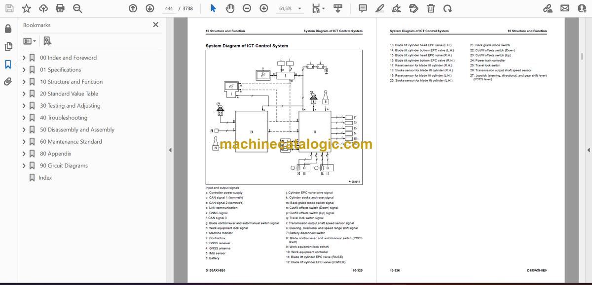
- System Diagram of ICT Control System
- Blade Control System
- Function of Blade Control System
- Leveling Mode System Diagram
- Function of Leveling Mode
- Operation of Leveling Mode
- Dozing Mode System Diagram
- Function of Dozing Mode
- Operation of Dozing Mode
- Smooth Start System
- Smooth Start System Diagram
- Function of Smooth Start System
- Operation of Smooth Start System
- Slip Control System
- Slip Control System Diagram
- Function of Slip Control System
- Operation of Slip Control System
- Assist Control System
- Assist Control System Diagram
- Function of Assist Control System
- Operation of Assist Control System
- Component Parts of ICT System
- Control Box
- GNSS Receiver
- GNSS Antenna
- IMU Sensor
- Stroke and Reset Sensor for Blade Lift Cylinder
- Undercarriage and Frame
- Main Frame
- Suspension
- Structure of Suspension
- Function of Suspension
- Track Frame and Idler Cushion
- Structure of Track Frame and Idler Cushion
- Specifications of Track Frame and Idler Cushion
- Function of Track Frame and Idler Cushion
- Work Equipment
- Structure of Front Work Equipment
- Structure of Cylinder Stay
- Structure of Variable Giant Ripper
- Structure of Variable Multi-Shank Ripper
- CAB Related Parts
- ROPS CAB
- Structure of ROPS CAB
- Function of ROPS CAB
- CAB Mount
- 20 Standard Value Table
- Table of Contents
- Standard Value Table for Engine
- Standard Value Table for Engine: D155AXI-8E0
- Standard Value Table for Machine
- Standard Value Table for Machine: D155AXI-8E0
- Machine Posture and Procedures to Measure Performance
- Standard Value Table for Electricity
- Standard Value Table for Electricity
- 30 Testing and Adjusting
- Table of Contents
- Precautions Before Work
- Related Information on Testing and Adjusting
- Tools for Testing and Adjusting
- Sketch of Tools for Testing and Adjusting
- Engine and Cooling System
- Examine Engine Speed
- How to Examine Engine Speed
- Examine Boost Pressure
- How to Examine Boost Pressure
- Examine Exhaust Gas Temperature
- How to Examine Exhaust Gas Temperature
- Examine Exhaust Gas Color
- How to Examine Exhaust Gas Color with the Handy Smoke Checker
- How to Examine Exhaust Gas Color with Smoke Meter
- Examine Mass Air Flow and Temperature Sensor
- How to Examine Mass Air Flow and Temperature Sensor
- Examine and Adjust Valve Clearance
- How to Examine Valve Clearance
- How to Adjust Valve Clearance
- Examine Compression Pressure
- How to Examine Compression Pressure
- Examine Blowby Pressure
- How to Examine Blowby Pressure
- Examine Engine Oil Pressure
- How to Examine Engine Oil Pressure on Machine Monitor
- How to Examine Engine Oil Pressure by Testing Tool
- Examine EGR Valve and VGT Oil Pressure
- How to Examine EGR Valve and VGT Oil Pressure
- Examine Fuel Pressure
- How to Examine Fuel Pressure
- Examine Fuel Return Rate and Leakage
- How to Examine Fuel Return Rate and Leakage
- Bleed Air from Fuel System
- How to Bleed Air from Fuel System
- Examine Fuel Circuit for Leakage
- How to Examine Fuel System for Leakage
- Handle Cylinder Cut-out Mode Operation
- Handle No-Injection Cranking Operation
- Clean Fuel Doser
- Write Injector Compensation Value to Engine Controller
- How to Write Injector Compensation Value
- Correct Soot Accumulation Correction Value by Ash Influence
- How to Correct Soot Accumulation Correction Value by Ash Influence
- Examine SCR Related Functions
- Examine DEF Pump Raised Pressure
- Examine Injection Volume from DEF Injector
- Examine DEF Line Heater Relay 1
- Examine DEF Line Heater Relay 2
- Examine DEF Pump Heater Relay
- Examine DEF Tank Heater Valve
- Examine SCR Denitration Efficiency
- Clean DEF Tank
- Clean DEF Pump
- Adjust Decelerator Pedal
- How to Adjust Decelerator Pedal
- Power Train
- Examine Power Train Oil Pressure
- How to Examine Power Train Oil Pressure
- Adjust Transmission Output Shaft Speed Sensor
- How to Adjust Transmission Output Shaft Speed Sensor
- Examine Brake Performance Simply
- How to Examine Brake Performance Simply
- Examine and Adjust Brake Pedal
- How to Examine Brake Pedal
- How to Adjust Brake Pedal
- Adjust Parking Brake Lever
- How to Adjust Parking Brake Lever
- Move Machine by Parking Brake Release When Machine Does Not Travel
- How to Move Machine with Hydraulic Type Parking Brake Release System
- How to Move Machine with Electric Type Parking Brake Release System
- Undercarriage and Frame
- Adjust Idler Clearance
- How to Adjust Idler Clearance
- Examine and Adjust Track Tension
- How to Examine Track Tension
- How to Adjust Track Tension
- Hydraulic System
- Release Remained Pressure in Hydraulic Circuit
- How to Release Remained Pressure from Hydraulic Circuit
- Examine and Adjust Work Equipment and HSS Oil Pressure
- How to Examine Work Equipment and HSS Oil Pressure
- How to Adjust Oil Pressure of Work Equipment and HSS
- Examine Oil Pressure of Control Circuit
- How to Examine Oil Pressure in Control Circuit
- Examine Work Equipment Lock Solenoid Valve Outlet Pressure
- How to Examine Work Equipment Lock Solenoid Valve Outlet Pressure
- Examine Ripper Pin Puller Solenoid Valve Outlet Pressure
- How to Examine Ripper Pin Puller Solenoid Valve Outlet Pressure
- Examine Cooling Fan Speed
- How to Examine Cooling Fan Speed
- Examine Cooling Fan Circuit Oil Pressure
- How to Examine Cooling Fan Circuit Oil Pressure
- Bleed Air in Cooling Fan Pump
- How to Bleed Air in Cooling Fan Pump
- Examine Parts Which Cause Hydraulic Drift of Work Equipment
- How to Examine Parts Which Cause Hydraulic Drift of Blade Lift Cylinder
- How to Examine the Parts Which Cause Hydraulic Drift of Blade Tilt Cylinder
- How to Examine the Parts Which Cause Hydraulic Drift of Ripper Lift Cylinder
- Examine Oil Leakage from Work Equipment Cylinder
- How to Examine Internal Oil Leakage of Work Equipment Cylinder
- Bleed Air from Work Equipment Cylinders
- How to Bleed Air from Work Equipment Cylinder
- Operation When Work Equipment is Disabled
- How to Operate When Work Equipment is Disabled
- Work Equipment
- Adjust Work Equipment Lock Lever
- How to Adjust Work Equipment Lock Lever
- Examine and Adjust Play of Blade Electric Lever
- How to Examine Play of Blade Electric Lever
- How to Adjust Play of Blade Electric Lever
- How to Replace Universal Joint
- CAB Related Parts
- Examine and Adjust Operator Cab
- How to Examine Operator Cab
- How to Adjust Operator Cab
- Electrical System
- Set and Operate Machine Monitor
- Operator Mode
- Function to Show Technician Identification Status Screen
- Function to Show Operator Identification Input Screen
- Examine Function by LCD (Liquid Crystal Display)
- Examine Function of Service Meter
- How to Set Usage Limitation and Change Maintenance Password
- Service Mode
- How to Operate Service Mode
- How to See Pre-defined Monitoring Information
- How to Examine Self-Define Monitor Information
- Abnormality Record Menu
- How to See Maintenance Record
- Maintenance Mode Setting
- How to Set Phone Number Entry
- Default Menu
- Diagnostic Tests Menu
- Adjustment Menu
- No-Injection Cranking Operation
- KOMTRAX Settings Menu
- How to Show Service Message
- How to Start Up KOMTRAX Terminal (Machine with KOMTRAX Terminal)
- Stop Use of KOMTRAX Terminal (Machine with KOMTRAX Terminal)
- How to Start Up KOMTRAX System (Machine with Gateway Function Controller)
- Stop Use of KOMTRAX System (Machine with Gateway Function Controller)
- Adjust Rearview Camera Angle
- How to Adjust Rearview Camera Angle
- Handle Voltage Circuit of Engine Controller
- Handle Battery Disconnect Switch
- Examine Diodes
- How to Examine Diodes by Digital Tester
- How to Examine Diodes by Analog Tester
- ICT System
- Set and Operate Control Box
- Examine and Adjust ICT Related Devices (Dual Tilt)
- Examine and Adjust ICT Related Devices (Single Tilt)
- Calibrate Blade Edge Position
- How to Operate Blade Calibration Menu (Pitch Rod Calibration) (Single Tilt)
- How to Operate Blade Calibration Menu (Machine Cal Step A) (Dual Tilt)
- How to Operate Blade Calibration Menu (Machine Cal Step A) (Single Tilt)
- How to Operate Blade Calibration Menu (Machine Cal Step B) (Dual Tilt)
- How to Operate Blade Calibration Menu (Machine Cal Step B) (Single Tilt)
- Calibrate IMU Sensor
- How to Calibrate IMU Sensor
- Reset Cylinder Stroke End
- Reset Lift Cylinder Stroke End
- Set Standard Angle of Blade Edge (Dual Tilt)
- How to Input Wear Volume of Blade Edge and Track Shoes
- Examine and Adjust Blade Elevation
- Examine Blade Elevation (Dual Tilt) (For Old Control Box)
- Examine Blade Elevation (Dual Tilt) (For New Control Box)
- Examine Blade Elevation (Single Tilt) (For Old Control Box)
- Examine Blade Elevation (Single Tilt) (For New Control Box)
- Adjust Blade Elevation (For Old Control Box)
- Adjust Blade Elevation (For New Control Box)
- Examine Stroke Sensor for Lift Cylinder
- How to Examine Stroke Sensor for Lift Cylinder
- Examine and Adjust Reset Sensor for Lift Cylinder
- How to Examine Reset Sensor for Lift Cylinder
- How to Adjust Reset Sensor for Lift Cylinder
- Adjust When Work Equipment Controller is Replaced
- How to Adjust When Work Equipment Controller is Replaced
- Adjust When ICT Related Devices are Repaired or Replaced (Dual Tilt)
- Adjust When ICT Related Devices are Repaired or Replaced (Single Tilt)
- Pm Clinic
- Pm Clinic Service
- Pm Clinic Check Sheet: D155AXI-8E0
- Pm Clinic Check Sheet for Undercarriage: D155AXI-8E0
- 40 Troubleshooting
- Table of Contents
- Precautions Before Work
- Related Information to Troubleshooting
- General Troubleshooting Points
- Troubleshooting Points for Urea SCR System
- Sequence of Events in Troubleshooting
- Checks Before Troubleshooting
- Inspection Procedure Before Troubleshooting
- Test in Accordance with Testing Procedure
- Examine Fuel Level and Type
- Examine for Impure Ingredient in Fuel
- Examine DEF Level and Type
- Examine Fuel Prefilter
- Examine Fuel Main Filter
- Examine Water Pump for Leakage
- Examine Engine Oil Level (Oil Quantity in Oil Pan) and Type
- Examine Coolant Level (Reservoir Tank)
- Examine Air Cleaner Clogging
- Clean Outer Element
- Replace Element
- Examine Hydraulic Oil Level
- Examine Hydraulic Oil Strainer
- Examine Hydraulic Oil Filter
- Examine Oil Level in Power Train Case
- Examine Power Train Strainer
- Examine Power Train Filter
- Examine Oil Level in Damper Case
- Examine Oil Level in Final Drive Case
- How to Examine Electric Equipment
- Procedure for Troubleshooting
- Symptom and Troubleshooting Numbers
- Information Shown in Troubleshooting Table
- Connector List and Layout (Machine with KOMTRAX Terminal)
- Connectors List (Machine with Gateway Function Controller)
- Connector Layout (Machine with Gateway Function Controller)
- Connector Contact Connection Table
- T-Branch Box and T-Branch Adapter Table
- Fuse Location Table
- Precautions When You Clean and Replace KDPF (KCSF and KDOC)
- Prepare Short Circuit Electrical Connector (For Failure Codes [CA1883] and [CA3135])
- Failure Code Table (Machine with KOMTRAX Terminal)
- Failure Codes Table (Machine with Gateway Function Controller)
- Troubleshooting by Failure Code (Display of Code)
- Failure Code [1500L0]
- Failure Code [15SAL1]
- Failure Code [15SALH]
- Failure Code [15SBL1]
- Failure Code [15SBLH]
- Failure Code [15SEL1]
- Failure Code [15SELH]
- Failure Code [15SFL1]
- Failure Code [15SFLH]
- Failure Code [15SGL1]
- Failure Code [15SGLH]
- Failure Code [15SJL1]
- Failure Code [15SJLH]
- Failure Code [1800MW]
- Failure Code [2300NR]
- Failure Code [2301L1]
- Failure Code [2301LH]
- Failure Code [2302L1]
- Failure Code [2302LH]
- Failure Code [879AKA]
- Failure Code [879AKB]
- Failure Code [879BKA]
- Failure Code [879BKB]
- Failure Code [879CKA]
- Failure Code [879CKB]
- Failure Code [879DKZ]
- Failure Code [879EMC]
- Failure Code [879FMC]
- Failure Code [879GKX]
- Failure Code [989L00]
- Failure Code [989M00]
- Failure Code [989N00]
- Failure Code [A1U0N3]
- Failure Code [A1U0N4]
- Failure Code [AA10NX]
- Failure Code [AB00KE]
- Failure Code [AQ10N3]
- Failure Code [AS00N3]
- Failure Code [AS00R2]
- Failure Code [AS00R3]
- Failure Code [AS00R4]
- Failure Code [AS00R5]
- Failure Code [AS00R6]
- Failure Code [AS00ZK]
- Failure Code [AS10KM]
- Failure Code [AS10NR]
- Failure Code [AS10NT]
- Failure Code [B@BAZG]
- Failure Code [B@BCNS]
- Failure Code [B@BCQA]
- Failure Code [B@BCZK]
- Failure Code [B@CENS]
- Failure Code [B@HANS]
- Failure Code [CA115]
- Failure Code [CA122]
- Failure Code [CA123]
- Failure Code [CA131]
- Failure Code [CA132]
- Failure Code [CA135]
- Failure Code [CA141]
- Failure Code [CA144]
- Failure Code [CA145]
- Failure Code [CA153]
- Failure Code [CA154]
- Failure Code [CA187]
- Failure Code [CA221]
- Failure Code [CA222]
- Failure Code [CA227]
- Failure Code [CA234]
- Failure Code [CA238]
- Failure Code [CA239]
- Failure Code [CA249]
- Failure Code [CA256]
- Failure Code [CA271]
- Failure Code [CA272]
- Failure Code [CA273]
- Failure Code [CA274]
- Failure Code [CA322]
- Failure Code [CA323]
- Failure Code [CA324]
- Failure Code [CA325]
- Failure Code [CA331]
- Failure Code [CA332]
- Failure Code [CA343]
- Failure Code [CA351]
- Failure Code [CA352]
- Failure Code [CA356]
- Failure Code [CA357]
- Failure Code [CA386]
- Failure Code [CA441]
- Failure Code [CA442]
- Failure Code [CA449]
- Failure Code [CA451]
- Failure Code [CA452]
- Failure Code [CA515]
- Failure Code [CA516]
- Failure Code [CA553]
- Failure Code [CA555]
- Failure Code [CA556]
- Failure Code [CA559]
- Failure Code [CA595]
- Failure Code [CA687]
- Failure Code [CA689]
- Failure Code [CA691]
- Failure Code [CA692]
- Failure Code [CA697]
- Failure Code [CA698]
- Failure Code [CA731]
- Failure Code [CA778]
- Failure Code [CA1117]
- Failure Code [CA1664]
- Failure Code [CA1669]
- Failure Code [CA1673]
- Failure Code [CA1677]
- Failure Code [CA1678]
- Failure Code [CA1682]
- Failure Code [CA1683]
- Failure Code [CA1684]
- Failure Code [CA1686]
- Failure Code [CA1691]
- Failure Code [CA1694]
- Failure Code [CA1695]
- Failure Code [CA1696]
- Failure Code [CA1712]
- Failure Code [CA1713]
- Failure Code [CA1714]
- Failure Code [CA1715]
- Failure Code [CA1776]
- Failure Code [CA1777]
- Failure Code [CA1843]
- Failure Code [CA1844]
- Failure Code [CA1879]
- Failure Code [CA1881]
- Failure Code [CA1883]
- Failure Code [CA1885]
- Failure Code [CA1887]
- Failure Code [CA1921]
- Failure Code [CA1922]
- Failure Code [CA1923]
- Failure Code [CA1924]
- Failure Code [CA1925]
- Failure Code [CA1927]
- Failure Code [CA1928]
- Failure Code [CA1942]
- Failure Code [CA1963]
- Failure Code [CA1977]
- Failure Code [CA1993]
- Failure Code [CA2185]
- Failure Code [CA2186]
- Failure Code [CA2249]
- Failure Code [CA2265]
- Failure Code [CA2266]
- Failure Code [CA2271]
- Failure Code [CA2272]
- Failure Code [CA2349]
- Failure Code [CA2353]
- Failure Code [CA2357]
- Failure Code [CA2381]
- Failure Code [CA2382]
- Failure Code [CA2383]
- Failure Code [CA2386]
- Failure Code [CA2387]
- Troubleshooting Flowchart
- Failure Code [CA2555]
- Failure Code [CA2556]
- Failure Code [CA2637]
- Failure Code [CA2639]
- Failure Code [CA2732]
- Failure Code [CA2733]
- Failure Code [CA2741]
- Failure Code [CA2765]
- Failure Code [CA2771]
- Failure Code [CA2777]
- Failure Code [CA2878]
- Failure Code [CA2881]
- Failure Code [CA2976]
- Failure Code [CA3133]
- Failure Code [CA3134]
- Failure Code [CA3135]
- Failure Code [CA3142]
- Failure Code [CA3143]
- Failure Code [CA3144]
- Failure Code [CA3146]
- Failure Code [CA3147]
- Failure Code [CA3148]
- Failure Code [CA3151]
- Failure Code [CA3165]
- Failure Code [CA3167]
- Failure Code [CA3229]
- Failure Code [CA3231]
- Failure Code [CA3232]
- Failure Code [CA3235]
- Failure Code [CA3239]
- Failure Code [CA3241]
- Failure Code [CA3242]
- Failure Code [CA3251]
- Failure Code [CA3253]
- Failure Code [CA3254]
- Failure Code [CA3255]
- Failure Code [CA3256]
- Failure Code [CA3311]
- Failure Code [CA3312]
- Failure Code [CA3313]
- Failure Code [CA3314]
- Failure Code [CA3315]
- Failure Code [CA3316]
- Failure Code [CA3317]
- Failure Code [CA3318]
- Failure Code [CA3319]
- Failure Code [CA3321]
- Failure Code [CA3322]
- Failure Code [CA3419]
- Failure Code [CA3421]
- Failure Code [CA3497]
- Failure Code [CA3498]
- Failure Code [CA3543]
- Failure Code [CA3545]
- Failure Code [CA3547]
- Failure Code [CA3558]
- Failure Code [CA3559]
- Failure Code [CA3562]
- Failure Code [CA3563]
- Failure Code [CA3567]
- Failure Code [CA3568]
- Failure Code [CA3571]
- Failure Code [CA3572]
- Failure Code [CA3574]
- Failure Code [CA3575]
- Failure Code [CA3577]
- Failure Code [CA3578]
- Failure Code [CA3582]
- Failure Code [CA3583]
- Failure Code [CA3596]
- Failure Code [CA3649]
- Failure Code [CA3681]
- Failure Code [CA3682]
- Failure Code [CA3713]
- Failure Code [CA3717]
- Failure Code [CA3718]
- Failure Code [CA3725]
- Failure Code [CA3748]
- Failure Code [CA3751]
- Failure Code [CA3755]
- Failure Code [CA3866]
- Failure Code [CA3867]
- Failure Code [CA3868]
- Failure Code [CA3899]
- Failure Code [CA3911]
- Failure Code [CA3912]
- Failure Code [CA3932]
- Failure Code [CA3933]
- Failure Code [CA3934]
- Failure Code [CA3935]
- Failure Code [CA3936]
- Failure Code [CA4151]
- Failure Code [CA4152]
- Failure Code [CA4155]
- Failure Code [CA4156]
- Failure Code [CA4157]
- Failure Code [CA4158]
- Failure Code [CA4159]
- Failure Code [CA4161]
- Failure Code [CA4162]
- Failure Code [CA4163]
- Failure Code [CA4164]
- Failure Code [CA4165]
- Failure Code [CA4166]
- Failure Code [CA4168]
- Failure Code [CA4169]
- Failure Code [CA4171]
- Failure Code [CA4249]
- Failure Code [CA4251]
- Failure Code [CA4259]
- Failure Code [CA4261]
- Failure Code [CA4277]
- Failure Code [CA4281]
- Failure Code [CA4459]
- Failure Code [CA4461]
- Failure Code [CA4658]
- Failure Code [CA4731]
- Failure Code [CA4732]
- Failure Code [CA4739]
- Failure Code [CA4768]
- Failure Code [CA4769]
- Failure Code [CA4842]
- Failure Code [CA4952]
- Failure Code [CA5115]
- Failure Code [CA5383]
- Failure Code [D130KA]
- Failure Code [D130KB]
- Failure Code [D190KA]
- Failure Code [D190KB]
- Failure Code [D19JKZ]
- Failure Code [D19UKA]
- Failure Code [D19UKB]
- Failure Code [D19UMC]
- Failure Code [D1EXKA]
- Failure Code [D1EXKB]
- Failure Code [D1EXKC]
- Failure Code [D811MC] (Machine with KOMTRAX Terminal)
- Failure Code [D811MC] (Machine with Gateway Function Controller)
- Failure Code [D862KA] (Machine with KOMTRAX Terminal)
- Failure Code [D862KA] (Machine with Gateway Function Controller)
- Failure Code [D8ALKA] (Machine with KOMTRAX Terminal)
- Failure Code [D8ALKA] (Machine with Gateway Function Controller)
- Failure Code [D8ALKB] (Machine with KOMTRAX Terminal)
- Failure Code [D8ALKB] (Machine with Gateway Function Controller)
- Failure Code [D8AQKR]
- Failure Code [D8ARKR] (Machine with Gateway Function Controller)
- Failure Code [D8G1KT] (Machine with Gateway Function Controller)
- Failure Code [D8G6KT] (Machine with Gateway Function Controller)
- Failure Code [DAF0MB]
- Failure Code [DAF0MC]
- Failure Code [DAF8KB]
- Failure Code [DAF9KQ]
- Failure Code [DAFGMC]
- Failure Code [DAFLKA]
- Failure Code [DAFLKB]
- Failure Code [DAFQKR]
- Failure Code [DAZ9KQ]
- Failure Code [DAZQKR]
- Failure Code [DB2QKR]
- Failure Code [DB2RKR]
- Failure Code [DB90KT]
- Failure Code [DB90MC]
- Failure Code [DB91KK]
- Failure Code [DB92KK]
- Failure Code [DB92KT]
- Failure Code [DB95KK]
- Failure Code [DB97KK]
- Failure Code [DB99KQ]
- Failure Code [DB9LKA]
- Failure Code [DB9LKB]
- Failure Code [DB9QKR]
- Failure Code [DB9RKR]
- Failure Code [DBE0KT]
- Failure Code [DBE0MC]
- Failure Code [DBE1KK]
- Failure Code [DBE2KK]
- Failure Code [DBE2KT]
- Failure Code [DBE5KK]
- Failure Code [DBE6KK]
- Failure Code [DBE9KQ]
- Failure Code [DBELKA]
- Failure Code [DBELKB]
- Failure Code [DBEQKR]
- Failure Code [DBERKR]
- Failure Code [DBTSKR]
- Failure Code [DBUTKA]
- Failure Code [DD12KA]
- Failure Code [DD12KB]
- Failure Code [DD13KA]
- Failure Code [DD13KB]
- Failure Code [DD14KA]
- Failure Code [DD14KB]
- Failure Code [DDDDKA]
- Failure Code [DDDDKB]
- Failure Code [DDDDKX]
- Failure Code [DDKAKA]
- Failure Code [DDKAKB]
- Failure Code [DDKBKA]
- Failure Code [DDKBKB]
- Failure Code [DDKCL4]
- Failure Code [DDKEL4]
- Failure Code [DDKQKA]
- Failure Code [DDKQKB]
- Failure Code [DDKRKA]
- Failure Code [DDKRKB]
- Failure Code [DDKSKA]
- Failure Code [DDKSKB]
- Failure Code [DDN7L4]
- Failure Code [DDN8L4]
- Failure Code [DDNLKA]
- Failure Code [DDNLKB]
- Failure Code [DDTSL1]
- Failure Code [DDTSLH]
- Failure Code [DFA4KX]
- Failure Code [DFA4KZ]
- Failure Code [DFA4L8]
- Failure Code [DFA5KA]
- Failure Code [DFA5KY]
- Failure Code [DFA6KA]
- Failure Code [DFA6KY]
- Failure Code [DFA7KX]
- Failure Code [DFA7KZ]
- Failure Code [DFA7L8]
- Failure Code [DFA8KA]
- Failure Code [DFA8KY]
- Failure Code [DFA9KA]
- Failure Code [DFA9KY]
- Failure Code [DFAAKX]
- Failure Code [DFAAKZ]
- Failure Code [DFAAL8]
- Failure Code [DFABKA]
- Failure Code [DFABKY]
- Failure Code [DFACKA]
- Failure Code [DFACKY]
- Failure Code [DGS1KA]
- Failure Code [DGS1KX]
- Failure Code [DGT1KA]
- Failure Code [DGT1KX]
- Failure Code [DH21KA]
- Failure Code [DH21KY]
- Failure Code [DHA4KA]
- Failure Code [DHAAMA]
- Failure Code [DHACMA]
- Failure Code [DHT5KA]
- Failure Code [DHT5KY]
- Failure Code [DHT7KA]
- Failure Code [DHT7KY]
- Failure Code [DK10KA]
- Failure Code [DK10KB]
- Failure Code [DK30KA]
- Failure Code [DK30KX]
- Failure Code [DK30KY]
- Failure Code [DK30KZ]
- Failure Code [DK30L8]
- Failure Code [DK31KA]
- Failure Code [DK31KY]
- Failure Code [DK40KA]
- Failure Code [DK40KY]
- Failure Code [DK55KX]
- Failure Code [DK55KZ]
- Failure Code [DK55L8]
- Failure Code [DK56KA]
- Failure Code [DK56KY]
- Failure Code [DK57KA]
- Failure Code [DK57KY]
- Failure Code [DK80KA]
- Failure Code [DKH1KA]
- Failure Code [DKH1KY]
- Failure Code [DKSGL8]
- Failure Code [DKSHKA]
- Failure Code [DKSHKB]
- Failure Code [DKSJKA]
- Failure Code [DKSJKB]
- Failure Code [DKSKKA]
- Failure Code [DKSKKB]
- Failure Code [DKSKMB]
- Failure Code [DKSLL8]
- Failure Code [DKSMKA]
- Failure Code [DKSMKB]
- Failure Code [DKSNKA]
- Failure Code [DKSNKB]
- Failure Code [DKSPKA]
- Failure Code [DKSPKB]
- Failure Code [DKSPMB]
- Failure Code [DLM3KA]
- Failure Code [DLM3KB]
- Failure Code [DLM3MB]
- Failure Code [DLT3KA]
- Failure Code [DLT3KB]
- Failure Code [DR21KX]
- Failure Code [DR31KX]
- Failure Code [DV20KB]
- Failure Code [DW7BKA]
- Failure Code [DW7BKB]
- Failure Code [DWN1KA] (Applicable Machine: 100358 to 100834)
- Failure Code [DWN1KA] (Applicable Machine: 100835 and up)
- Failure Code [DWN1KB] (Applicable Machine: 100358 to 100834)
- Failure Code [DWN1KB] (Applicable Machine: 100835 and up)
- Failure Code [DWN1KY] (Applicable Machine: 100358 to 100834)
- Failure Code [DWN1KY] (Applicable Machine: 100835 and up)
- Failure Code [DWN2KA] (Applicable Machine: 100358 to 100834)
- Failure Code [DWN2KA] (Applicable Machine: 100835 and up)
- Failure Code [DWN2KB] (Applicable Machine: 100358 to 100834)
- Failure Code [DWN2KB] (Applicable Machine: 100835 and up)
- Failure Code [DWN2KY] (Applicable Machine: 100358 to 100834)
- Failure Code [DWN2KY] (Applicable Machine: 100835 and up)
- Failure Code [DWN3KA]
- Failure Code [DWN3KB]
- Failure Code [DWN3KY]
- Failure Code [DWN5KA]
- Failure Code [DWN5KB]
- Failure Code [DWN5KY]
- Failure Code [DXA2KA]
- Failure Code [DXA2KB]
- Failure Code [DXA2KY]
- Failure Code [DXH1KA]
- Failure Code [DXH1KB]
- Failure Code [DXH1KY]
- Failure Code [DXH4KA]
- Failure Code [DXH4KB]
- Failure Code [DXH4KY]
- Failure Code [DXH5KA]
- Failure Code [DXH5KB]
- Failure Code [DXH5KY]
- Failure Code [DXH6KA]
- Failure Code [DXH6KB]
- Failure Code [DXH6KY]
- Failure Code [DXH7KA]
- Failure Code [DXH7KB]
- Failure Code [DXH7KY]
- Failure Code [DXH8KA]
- Failure Code [DXH8KB]
- Failure Code [DXH8KY]
- Failure Code [DXHBKA]
- Failure Code [DXHBKB]
- Failure Code [DXHBKY]
- Failure Code [DXHCKA]
- Failure Code [DXHCKB]
- Failure Code [DXHCKY]
- Failure Code [DXHRKA]
- Failure Code [DXHRKB]
- Failure Code [DXHRKY]
- Failure Code [DXHSKA]
- Failure Code [DXHSKB]
- Failure Code [DXHSKY]
- Failure Code [DXHTKA]
- Failure Code [DXHTKB]
- Failure Code [DXHTKY]
- Failure Code [DXHUKA]
- Failure Code [DXHUKB]
- Failure Code [DXHUKY]
- Failure Code [DXHWKA]
- Failure Code [DXHWKB]
- Failure Code [DXHWKY]
- Failure Code [DXHXKA] (Applicable Machine: 100358 to 100834)
- Failure Code [DXHXKA] (Applicable Machine: 100835 and up)
- Failure Code [DXHXKB] (Applicable Machine: 100358 to 100834)
- Failure Code [DXHXKB] (Applicable Machine: 100835 and up)
- Failure Code [DXHXKY] (Applicable Machine: 100358 to 100834)
- Failure Code [DXHXKY] (Applicable Machine: 100835 and up)
- Failure Code [DXHYKA] (Applicable Machine: 100358 to 100834)
- Failure Code [DXHYKA] (Applicable Machine: 100835 and up)
- Failure Code [DXHYKB] (Applicable Machine: 100358 to 100834)
- Failure Code [DXHYKB] (Applicable Machine: 100835 and up)
- Failure Code [DXHYKY] (Applicable Machine: 100358 to 100834)
- Failure Code [DXHYKY] (Applicable Machine: 100835 and up)
- Failure Code [DXHZKA] (Applicable Machine: 100358 to 100834)
- Failure Code [DXHZKA] (Applicable Machine: 100835 and up)
- Failure Code [DXHZKB] (Applicable Machine: 100358 to 100834)
- Failure Code [DXHZKB] (Applicable Machine: 100835 and up)
- Failure Code [DXHZKY] (Applicable Machine: 100358 to 100834)
- Failure Code [DXHZKY] (Applicable Machine: 100835 and up)
- Failure Code [DXJ4KA]
- Failure Code [DXJ4KB]
- Failure Code [DXJ8KA]
- Failure Code [DXJ8KB]
- Failure Code [DXJ8KY]
- Failure Code [DXJ9KA]
- Failure Code [DXJ9KB]
- Failure Code [DXJ9KY]
- Failure Code [DXJAKA]
- Failure Code [DXJAKB]
- Failure Code [DXJAKY]
- Failure Code [DXJBKA]
- Failure Code [DXJBKB]
- Failure Code [DXJBKY]
- Failure Code [F311KA]
- Failure Code [F311KB]
- Failure Code [F312KA]
- Failure Code [F312KB]
- Failure Code [F313KA]
- Failure Code [F313KB]
- Failure Code [F314KA]
- Failure Code [F314KB]
- Failure Code [F315KB]
- Failure Code [F315KY]
- Failure Code [F316KB]
- Failure Code [F316KY]
- Failure Code [F318KB]
- Failure Code [F318KY]
- Failure Code [F31AKB]
- Failure Code [F31AKY]
- Failure Code [F31BKB]
- Failure Code [F31BKY]
- Failure Code [F31CKB]
- Failure Code [F31CKY]
- Failure Code [F31DKB]
- Failure Code [F31DKY]
- Failure Code [F31EKB]
- Failure Code [F31EKY]
- Troubleshooting of Electrical System (E-Mode)
- E-1 Engine Does Not Start (Engine Does Not Crank)
- E-2 Manual Preheating System Does Not Operate
- E-3 Automatic Preheating System Does Not Operate
- E-4 While Preheating is in Operation, Preheating Monitor Does Not Come On
- E-5 When Starting Switch is Turned to ON Position, Machine Monitor Shows Nothing
- E-6 While Starting Switch is Turned to ON Position (with Engine Stopped), Radiator Coolant Level Monitor Comes On in Yellow
- E-7 Air Cleaner Clogging Monitor Comes On in Yellow While Engine is in Operation
- E-8 Charge Level Monitor Comes On in Red While Engine is in Operation
- E-9 Engine Coolant Temperature Monitor Comes On in Red While Engine is in Operation
- E-10 Engine Oil Pressure Monitor Comes on in Red While Engine is in Operation
- E-11 Power Train Oil Temperature Monitor Comes On in Red While Engine is in Operation
- E-12 Hydraulic Oil Temperature Monitor Comes On in Red While Engine is in Operation
- E-13 Engine Coolant Temperature Gauge Does Not Show Correct Temperature
- E-14 Fuel Gauge Does Not Show Normally
- E-15 Power Train Oil Temperature Gauge Does Not Show Correct Temperature
- E-16 Hydraulic Oil Temperature Gauge Does Not Show Correct Temperature
- E-17 Operation Mode Does Not Change
- E-18 Gear Shift Mode Does Not Change
- E-19 Operating Customize Switch Does Not Display Customize Screen
- E-20 Modifying Setting on Customize Screen Does Not Change Setting of Machine
- E-21 Some Areas of Machine Monitor Screen are Not Shown
- E-22 Alarm Buzzer Does Not Sound or Cannot be Stopped
- E-23 Service Meter is Not Shown, While Starting Switch is in OFF Position
- E-24 Machine Does Not Change to Service Mode
- E-25 Horn Does Not Sound
- E-26 Horn Does Not Stop
- E-27 Backup Alarm Does Not Sound
- E-28 Backup Alarm Does Not Stop
- E-29 Headlamp Does Not Come On
- E-30 Rear Lamp and Ripper Point Lamp Do Not Come On
- E-31 No Wiper Operates
- E-32 Front Wiper Does Not Operate
- E-33 Rear Wiper Does Not Operate
- E-34 Left Door Wiper Does Not Operate
- E-35 Right Door Wiper Does Not Operate
- E-36 Fuel Feed Pump Does Not Operate or Stop Automatically
- E-37 Fan Does Not Rotate in Reverse
- E-38 Gear Cannot be Shifted
- E-39 Front Washer Does Not Operate
- E-40 Rear Washer Does Not Operate
- E-41 Left Door Washer Does Not Operate
- E-42 Right Door Washer Does Not Operate
- E-43 Ripper Pin Puller Does Not Work
- E-44 KOMTRAX System Does Not Operate Correctly
- E-45 Control Box Shuts Down After It Shows Messages [GPS receiver not connected !] and [Slope sensor not connected !]
- E-46 Control Box Shows Messages [GPS receiver not connected !] and [Slope sensor not connected !]
- E-47 Control Box Shows Message [Waiting for radio link…]
- E-48 Control Box Shows Message [IMU sensor not connected]
- E-49 Control Box Shows Message [Waiting for satellites…]
- E-50 Control Box Shows Message [Komatsu controller not connected!] Show Production
- E-51 Control Box Shows Message [Cylinder Stroke Reading Abnormal]
- E-52 Control Box Shows Message [Komatsu CAN Comms Abnormal]
- E-53 Control Box Shows Message [Komatsu Machine Trouble]
- E-54 Control Box Shows Message [Waiting to initialize….]
- E-55 Control Box Shows Message [System Initializing]
- E-56 Control Box Shows Message [Initializing….]
- E-57 Control Box Shows Message [Configuring GPS]
- E-58 Control Box Shows Message [No GPS Localization…]
- E-59 Control Box Shows Message [Low precisions…]
- E-60 Control Box Shows Message [Heading Initializing]
- E-61 Control Box Displays [Out of design area…]
- E-62 Control Box Can Not be Turned on
- E-63 Control Box Does Not Display Intelligent Machine Control Screen
- E-64 Control Box Does Not Display Bulldozer Image
- E-65 Control Box Does Not Display Design Surface
- E-66 Control Box Touch Panel Does Not Respond
- E-67 Control Box Touch Panel is Inaccurate
- E-68 Cylinder Stroke Reset Indication Does Not Go Out
- E-69 AUTO is Not Shown When AUTO/Manual Switch is Pushed (AUTO Indication Goes Out)
- E-70 Blade Automatic Lower Control Does Not Start While AUTO is Shown
- E-71 Blade Automatic Raise Control Does Not Start While AUTO is Shown
- E-72 Blade Automatic Control Function is Not Activated While AUTO is Shown (Blade Automatic Control Stops)
- E-73 When You Examine and Adjust the Blade Elevation, the Value is Different from Actual Machine
- E-74 Finished Surface is Inaccurate (The Average Height of Finished Surface is Lower Than Designed Surface or Blade Does Not Touch the Surface)
- E-75 Finished Surface is Inaccurate (The Finished Surface is Not Smooth)
- E-76 Finished Surface is Inaccurate (When You Finish Slope Horizontally, Steps are Made in Each Direction)
- E-77 Machine Can Not Escape from Shoes Slip While Blade Automatic Control is Activated (Shoes Frequently Slips)
- E-78 Blade Tilt Angle Does Not Align with Design Surface
- E-79 When You Push Cut/Fill Level Switch (Raise), the Design Surface Does Not Rise
- E-80 When You Push Cut/Fill Level Switch (Lower), the Design Surface Does Not Lower
- E-81 When Starting Switch is Turned to ON Position, Reverse Leveling Mode Switch LED Does Not Come On or Does Not Go Out
- E-82 When Reverse Leveling Mode Switch is Pushed, Buzzer Does Not Sound (Does Not Switch to Reverse Leveling Mode)
- Troubleshooting for Hydraulic and Mechanical Systems (H Mode)
- Information Shown in Troubleshooting Table (H-Mode)
- System Chart of Hydraulic and Mechanical Systems
- Failure Mode and Cause Table
- H-1 Machine Power is Not Sufficient (Not Sufficient Drawbar Pull)
- H-2 Machine Does Not Travel (at 2nd or 3rd Gear Speed)
- H-3 Machine Does Not Move Off at All Gear Speeds
- H-4 Machine Travels Only in One Direction, Forward or in Reverse
- H-5 Large Time Lag is in Gear Shifting or Directional Change
- H-6 Brake Does Not Work
- H-7 Power Train Oil Overheats
- H-8 Unusual Noise is Heard from Around Work Equipment and HSS Pump or HSS Motor
- H-9 Torque Converter Lockup Clutch Does Not Engage
- H-10 Machine Cannot be Steered (Machine Does Not Turn LEFT or RIGHT)
- H-11 Steering Speed or Power is Not Sufficient
- H-12 All Work Equipment Operate Slowly
- H-13 All Work Equipment Do Not Operate
- H-14 Blade Lift Speed or Power is Low
- H-15 Blade Tilt Speed or Power is Low
- H-16 Ripper Lift Speed or Power is Low
- H-17 Ripper Tilt Speed or Power is Low
- H-18 Hydraulic Drift of Blade Lift is Large
- H-19 Hydraulic Drift of Tilted Blade is Large
- H-20 Hydraulic Drift of Lifted Ripper is Large
- H-21 Ripper Pin Puller Cylinder Does Not Operate
- H-22 Blade Pitch Cylinder Does Not Operate
- H-23 Fan Speed is Abnormal (Too High or Low, or Does Not Rotate)
- H-24 Unusual Noise is Heard from Around Fan
- Troubleshooting of Engine (S-Mode)
- Information Shown in Troubleshooting Table (S-Mode)
- S-1 Engine Does Not Crank When Starting Switch is Turned to Start Position
- S-2 Engine Cranks but No Exhaust Smoke Comes Out
- S-3 Fuel is Injected but Engine Does Not Start (Misfiring: Engine Cranks but Does Not Start)
- S-4 Engine Startability is Unsatisfactory
- S-5 Engine Does Not Pick Up Smoothly
- S-6 Engine Stops During Operation
- S-7 Engine Runs Rough or is Not Stable
- S-8 Engine Lacks Power
- S-9 KDPF Becomes Clogged in a Short Time
- S-10 Engine Oil Consumption is Excessive
- S-11 Oil Becomes Dirty Quickly
- S-12 Fuel Consumption is Excessive
- S-13 Oil is in Coolant (or Coolant Spurts Back or Coolant Level goes Down)
- S-14 Oil Pressure Drops
- S-15 Fuel Mixes Into Engine Oil
- S-16 Water Mixes Into Engine Oil (Milky)
- S-17 Coolant Temperature Increases Too High (Overheating)
- S-18 Unusual Noise is Heard
- S-19 Vibration is Excessive
- S-20 Air Cannot be Bled from Fuel Circuit
- S-21 Active Regeneration is Done Frequently
- S-22 Active Regeneration Continues Long
- S-23 White Smoke is Exhausted During Active Regeneration
- S-24 DEF Consumption is Excessive
- S-25 There is Unusual Smell (Irritating Odor)
- S-26 Foreign Materials Enter DEF (DEF Increases)
- 50 Disassembly and Assembly
- Table of Contents
- Precautions Before Work
- Related Information on Disassembly and Assembly
- How to Read This Manual
- Coating Materials List
- Special Tool List
- Sketches of Special Tools
- Engine and Cooling System
- Remove and Install Supply Pump Assembly
- How to Remove Supply Pump Assembly
- How to Install Supply Pump Assembly
- Remove and Install Injector Assembly
- How to Remove Injector Assembly
- How to Install Injector Assembly
- Remove and Install Fuel Doser Assembly
- How to Remove Fuel Doser Assembly
- How to Install Fuel Doser Assembly
- Remove and Install Cylinder Head Assembly
- How to Remove Cylinder Head Assembly
- How to Install Cylinder Head Assembly
- Remove and Install EGR Valve Assembly
- How to Remove EGR Valve Assembly
- How to Install EGR Valve Assembly
- Remove and Install EGR Cooler Assembly
- How to Remove EGR Cooler Assembly
- How to Install EGR Cooler Assembly
- Remove and Install Starter Assembly
- How to Remove Starting Motor Assembly
- How to Install Starting Motor Assembly
- Remove and Install Alternator Belt
- How to Remove Alternator Belt
- How to Install Alternator Belt
- Remove and Install Radiator Assembly
- How to Remove Radiator Assembly
- How to Install Radiator Assembly
- Remove and Install Hydraulic Oil Cooler Assembly
- How to Remove Hydraulic Oil Cooler Assembly
- How to Install Hydraulic Oil Cooler Assembly
- Remove and Install Aftercooler Assembly
- How to Remove Aftercooler Assembly
- How to Install Aftercooler Assembly
- Remove and Install Cooling Fan Drive Assembly
- How to Remove Cooling Fan Drive Assembly
- How to Install Cooling Fan Drive Assembly
- Remove and Install Cooling Fan Motor Assembly
- How to Remove Cooling Fan Motor Assembly
- How to Install Cooling Fan Motor Assembly
- Remove and Install Engine Assembly
- How to Remove Engine Assembly
- How to Install Engine Assembly
- Remove and Install Engine Front Oil Seal
- How to Remove Engine Front Oil Seal
- How to Install Engine Front Oil Seal
- Remove and Install Engine Rear Oil Seal
- How to Remove Engine Rear Oil Seal
- How to Install Engine Rear Oil Seal
- Remove and Install Engine Hood Assembly
- How to Remove Engine Hood Assembly
- How to Install Engine Hood Assembly
- Remove and Install Fuel Tank Assembly
- How to Remove Fuel Tank Assembly
- How to Install Fuel Tank Assembly
- Remove and Install DEF Tank Assembly
- How to Remove DEF Tank Assembly
- How to Install DEF Tank Assembly
- Remove and Install DEF Tank Sensor Flange Assembly
- How to Remove DEF Tank Sensor Flange Assembly
- How to Install DEF Tank Sensor Flange Assembly
- Remove and Install DEF Tank Sensor
- How to Remove DEF Tank Sensor
- How to Install DEF Tank Sensor
- Remove and Install DEF Tank Strainer
- How to Remove DEF Tank Strainer
- How to Install DEF Tank Strainer
- Remove and Install DEF Tank Filler Port Filter
- How to Remove DEF Tank Filler Port Filter
- How to Install DEF Tank Filler Port Filter
- Remove and Install KDPF Assembly
- How to Remove KDPF Assembly
- How to Install KDPF Assembly
- Disassemble and Assemble KDPF Assembly
- How to Disassemble KDPF Assembly
- How to Assemble KDPF Assembly
- Remove and Install SCR Assembly
- How to Remove SCR Assembly
- How to Install SCR Assembly
- Remove and Install KDPF and SCR Assembly
- How to Remove KDPF and SCR Assembly
- How to Install KDPF and SCR Assembly
- Remove and Install KCCV Assembly
- How to Remove KCCV Assembly
- How to Install KCCV Assembly
- Remove and Install DEF Mixing Tube
- How to Remove DEF Mixing Tube
- How to Install DEF Mixing Tube
- Remove and Install DEF Injector
- How to Remove DEF Injector
- How to Install DEF Injector
- Remove and Install DEF Pump
- How to Remove DEF Pump
- How to Install DEF Pump
- Remove and Install DEF Hose
- How to Remove DEF Hose
- How to Install DEF Hose
- Remove and Install Air Cleaner Assembly
- How to Remove Air Cleaner Assembly
- How to Install Air Cleaner Assembly
- Remove and Install Air Conditioner Compressor Assembly
- How to Remove Air Conditioner Compressor Assembly
- How to Install Air Conditioner Compressor Assembly
- Remove and Install Air Conditioner Condenser Assembly
- How to Remove Air Conditioner Condenser Assembly
- How to Install Air Conditioner Condenser Assembly
- Power Train
- Remove and Install Damper Assembly
- How to Remove Damper Assembly
- How to Install Damper Assembly
- Disassemble and Assemble Damper Assembly
- How to Disassemble Damper Assembly
- How to Assemble Damper Assembly
- Remove and Install Power Train Unit Assembly
- How to Remove Power Train Unit Assembly
- How to Install Power Train Unit Assembly
- Disconnect and Connect Power Train Unit Assembly
- How to Disconnect Power Train Unit Assembly
- How to Connect Power Train Unit Assembly
- Disassemble and Assemble PTO Assembly
- How to Disassemble PTO Assembly
- How to Assemble PTO Assembly
- Disassemble and Assemble Torque Converter Assembly
- How to Disassemble Torque Converter Assembly
- How to Assemble Torque Converter Assembly
- Disassemble and Assemble Transmission Assembly
- How to Disassemble Transmission Assembly
- How to Assemble Transmission Assembly
- Disassemble and Assemble HSS Assembly
- How to Disassemble HSS Assembly
- How to Assemble HSS Assembly
- Remove and Install HSS Motor Assembly
- How to Remove HSS Motor Assembly
- How to Install HSS Motor Assembly
- Remove and Install Final Drive Assembly
- How to Remove Final Drive Assembly
- How to Install Final Drive Assembly
- Disassemble and Assemble Final Drive Assembly
- How to Disassemble Final Drive Assembly
- How to Assemble Final Drive Assembly
- Undercarriage and Frame
- Remove and Install Track Frame Assembly (Applicable Machine: 100001 to 100616)
- How to Remove Track Frame Assembly
- How to Install Track Frame Assembly
- Remove and Install Track Frame Assembly (Applicable Machine: 100617 and up)
- How to Remove Track Frame Assembly (Applicable Machine: 100617 and up)
- How to Install Track Frame Assembly (Applicable Machine: 100617 and up)
- Remove and Install Idler Assembly
- How to Remove Idler Assembly
- How to Install Idler Assembly
- Disassemble and Assemble Idler Assembly
- How to Disassemble Idler Assembly
- How to Assemble Idler Assembly
- Remove and Install Recoil Spring Assembly
- How to Remove Recoil Spring Assembly
- How to Install Recoil Spring Assembly
- Disassemble and Assemble Recoil Spring Assembly
- How to Disassemble Recoil Spring Assembly
- How to Assemble Recoil Spring Assembly
- Remove and Install Track Roller Assembly
- How to Remove Track Roller Assembly
- How to Install Track Roller Assembly
- Disassemble and Assemble Track Roller Assembly
- How to Disassemble Track Roller Assembly
- How to Assemble Track Roller Assembly
- Remove and Install No. 1 Bogie Assembly
- How to Remove No.1 Bogie Assembly
- How to Install No. 1 Bogie Assembly
- Remove and Install No. 2, 3, 4 Bogie Assemblies
- How to Remove No. 2, 3, 4 Bogie Assemblies
- How to Install No.2, 3, 4 Bogie Assemblies
- Disassemble and Assemble Bogie Assembly
- How to Disassemble Bogie Assembly
- How to Assemble Bogie Assembly
- Remove and Install Carrier Roller Assembly
- How to Remove Carrier Roller Assembly
- How to Install Carrier Roller Assembly
- Disassemble and Assemble Carrier Roller Assembly
- How to Disassemble Carrier Roller Assembly
- How to Assemble Carrier Roller Assembly
- Remove and Install Pivot Shaft Assembly
- How to Remove Pivot Shaft Assembly
- How to Install Pivot Shaft Assembly
- Separate and Connect Track Assembly
- How to Examine Before Separation of Track Assembly
- How to Separate Track Assembly (Standard)
- How to Separate Track Assembly (When Track Frame Has Internal Defect)
- How to Install Track Assembly
- Separate and Connect PLUS Type Track Assembly
- How to Separate PLUS Type Track Assembly
- Install PLUS Type Track Assembly
- Disassemble and Assemble Track Assembly Generally
- How to Disassemble Full Track Shoes Assembly
- How to Assemble Full Track Shoes Assembly
- Disassemble and Assemble PLUS Type Track Assembly Generally
- Disassemble PLUS Type Track Assembly Generally
- How to Assemble PLUS Type Track Shoes Assembly Generally
- Disassemble and Assemble One Track Link Assembly in Field
- How to Disassemble One Track Link Assembly in Field
- How to Assemble One Track Link Assembly in Field
- Disassemble and Assemble Master Link
- How to Disassemble Master Link
- How to Assemble Master Link
- Remove and Install Equalizer Bar Assembly
- How to Remove Equalizer Bar Assembly
- How to Install Equalizer Bar Assembly
- Disassemble and Assemble Equalizer Bar Bushing
- How to Disassemble Equalizer Bar Bushing
- How to Assemble Equalizer Bar Bushing
- Remove and Install Sprocket
- How to Remove Sprocket
- How to Install Sprocket
- Remove and Install Center Under Guard Assembly
- How to Remove Underguard Assembly
- How to Install Underguard Assembly
- Hydraulic System
- Remove and Install Hydraulic Tank Assembly
- How to Remove Hydraulic Tank Assembly
- How to Install Hydraulic Tank Assembly
- Remove and Install Work Equipment Pump and HSS Pump Assembly
- How to Remove Work Equipment Pump and HSS Pump Assembly
- How to Install Work Equipment Pump and HSS Pump Assembly
- Remove and Install Power Train Pump and Steering Lubrication Pump Assembly
- How to Remove Power Train Pump and Steering Lubrication Pump Assembly
- How to Install Power Train Pump and Steering Lubrication Pump Assembly
- Remove and Install Cooling Fan Pump Assembly
- How to Remove Cooling Fan Pump Assembly
- How to Install Cooling Fan Pump Assembly
- Remove and Install Scavenging Pump Assembly
- How to Remove Scavenging Pump Assembly
- How to Install Scavenging Pump Assembly
- Remove and Install Control Valve Assembly
- How to Remove Control Valve Assembly
- How to Install Control Valve Assembly
- Work Equipment
- Remove and Install Blade Assembly
- How to Remove Blade Assembly
- How to Install Blade Assembly
- Disassemble and Assemble Blade Assembly
- How to Disassemble Blade Assembly
- How to Assemble Blade Assembly
- Disassemble and Assemble Multi-Shank Ripper Assembly
- How to Disassemble Multi-Shank Ripper Assembly
- How to Assemble Multi-Shank Ripper Assembly
- Disassemble and Assemble Giant Ripper Assembly
- How to Disassemble Giant Ripper Assembly
- How to Assemble Giant Ripper Assembly
- Remove and Install Stroke and Reset Sensing Blade Lift Cylinder Assembly
- How to Remove Stroke and Reset Sensing Blade Lift Cylinder Assembly
- How to Install Stroke and Reset Sensing Blade Lift Cylinder Assembly
- Disassemble and Assemble Stroke and Reset Sensing Blade Lift Cylinder Assembly
- How to Disassemble Stroke and Reset Sensing Blade Lift Cylinder Assembly
- Assemble Stroke and Reset Sensing Blade Lift Cylinder Assembly
- Disassemble and Assemble Blade Tilt Cylinder Assembly
- How to Disassemble Blade Tilt Cylinder Assembly
- How to Assemble Blade Tilt Cylinder Assembly
- Disassemble and Assemble Ripper Cylinder Assembly
- How to Disassemble Ripper Cylinder Assembly
- How to Assemble Ripper Cylinder Assembly
- CAB Related Parts
- Remove and Install Operator Cab Assembly
- How to Remove Operator Cab Assembly
- How to Install Operator Cab Assembly
- Remove and Install Operator Cab Glass (Adhered Glass)
- How to Remove Operator Cab Glass (Adhered Glass)
- How to Install Operator Cab Glass (Adhered Glass)
- Remove and Install Air Conditioner Unit Assembly
- How to Remove Air Conditioner Unit Assembly
- How to Install Air Conditioner Unit Assembly
- Remove and Install Operator Seat
- How to Remove Operator Seat
- How to Install Operator Seat
- How to Remove and Install Seat Belt
- How to Remove Seat Belt
- How to Install Seat Belt
- Electrical System
- Remove and Install Engine Controller Assembly
- How to Remove Engine Controller Assembly
- How to Install Engine Controller Assembly
- Remove and Install Power Train Controller Assembly
- How to Remove Power Train Controller Assembly
- How to Install Power Train Controller Assembly
- Remove and Install Work Equipment Controller Assembly
- How to Remove Work Equipment Controller Assembly
- How to Install Work Equipment Controller Assembly
- Remove and Install Machine Monitor Assembly
- How to Remove Machine Monitor Assembly
- How to Install Machine Monitor Assembly
- Remove and Install Mass Air Flow and Temperature Sensor
- How to Remove Mass Air Flow and Temperature Sensor
- How to Install Mass Air Flow and Temperature Sensor
- Remove and Install KCCV Crankcase Pressure Sensor
- How to Remove KCCV Crankcase Pressure Sensor
- How to Install KCCV Crankcase Pressure Sensor
- Remove and Install SCR Temperature Sensor
- How to Remove SCR Temperature Sensor
- How to Install SCR Temperature Sensor
- Remove and Install Battery Relay
- How to Remove Battery Relay
- How to Install Battery Relay
- Remove and Install KOMTRAX Terminal Assembly
- How to Remove KOMTRAX Terminal Assembly
- How to Install KOMTRAX Terminal Assembly
- Remove and Install Gateway Controller Assembly
- How to Remove Gateway Controller Assembly
- How to Install Gateway Controller Assembly
- Remove and Install Communication Terminal
- How to Remove Communication Terminal
- How to Install Communication Terminal
- Remove and Install Communication Terminal Wiring Harness
- How to Remove Communication Terminal Wiring Harness
- How to Install Communication Terminal Wiring Harness
- Remove and Install Control Box
- How to Remove Control Box (For Old Control Box)
- How to Remove Control Box (For New Control Box)
- How to Install Control Box (For Old Control Box)
- How to Install Control Box (For New Control Box)
- Remove and Install GNSS Receiver
- How to Remove GNSS Receiver
- How to Install GNSS Receiver
- Remove and Install GNSS Antenna
- How to Remove GNSS Antenna
- How to Install GNSS Antenna
- Remove and Install IMU Sensor
- How to Remove IMU Sensor
- How to Install IMU Sensor
- 60 Maintenance Standard
- Table of Contents
- Engine and Cooling System
- Maintenance Standard for Engine Mount
- Maintenance Standard for Damper
- Maintenance Standard for Cooling System
- Maintenance Standard for Cooling Fan Pump
- Maintenance Standard for Servo Valve
- Maintenance Standard for Cooling Fan Motor
- Power Train
- Maintenance Standard for Universal Joint
- Maintenance Standard for Power Train Mount
- Maintenance Standard for Torque Converter and PTO
- Maintenance Standard for Torque Converter Control Valve
- Maintenance Standard for Lockup Clutch ECMV
- Maintenance Standard for Stator Clutch ECMV
- Maintenance Standard for Transmission
- Maintenance Standard for Transmission ECMV
- Maintenance Standard for Main Relief Valve and Torque Converter Relief Valve
- Maintenance Standard for Transmission Lubrication Relief Valve
- Maintenance Standard for Bevel Gear Shaft, HSS, and Brake
- Maintenance Standard for Brake Control Valve
- Maintenance Standard for Brake ECMV
- Maintenance Standard for Brake Solenoid Valve
- Maintenance Standard for Sudden Stop Prevention Valve
- Maintenance Standard for Final Drive
- Maintenance Standard for Sprocket for Conventional Type Track Shoes
- Maintenance Standard for Sprocket Tooth Profile Full-Scale Drawing for Conventional Type Track Shoes
- Maintenance Standard for Sprocket for PLUS Type Track Shoes
- Maintenance Standard for Sprocket Tooth Profile Full-Scale Drawing for PLUS Type Track Shoes
- Undercarriage and Frame
- Maintenance Standard for Main Frame
- Maintenance Standard for Suspension
- Maintenance Standard for Track Frame and Idler Cushion
- Maintenance Standard for Idler
- Maintenance Standard for Track Roller for Conventional Type Track Shoes
- Maintenance Standard for Track Roller for PLUS Type Track Shoes
- Maintenance Standard for Carrier Roller for Conventional Type Track Shoes
- Maintenance Standard for Carrier Roller for PLUS Type Track Shoes
- Maintenance Standard for Conventional Type Track Shoes
- Maintenance Standard for PLUS Type Track Shoes
- Maintenance Standard for Single Shoes and Heavy Duty Shoes
- Hydraulic System
- Maintenance Standard for Hydraulic Tank
- Maintenance Standard for Scavenging Pump
- Maintenance Standard for Steering Lubrication Pump and Power Train Pump
- Maintenance Standard for Work Equipment and HSS Pump
- Maintenance Standard for PC-EPC Valve
- Maintenance Standard for HSS Motor
- Maintenance Standard for Control Valve
- Maintenance Standard for Self-Pressure Reducing Valve
- Maintenance Standard for Quick Drop Valve
- Work Equipment
- Maintenance Standard for Cylinder Stay
- Maintenance Standard for Front Work Equipment
- Maintenance Standard for Cutting Edge and End Bit
- Maintenance Standard for Stroke and Reset Sensing Blade Lift Cylinder
- Maintenance Standard for Blade Tilt Cylinder
- Maintenance Standard for Variable Multi-Shank Ripper
- Maintenance Standard for Variable Giant Ripper
- Maintenance Standard for Ripper Lift Cylinder
- Maintenance Standard for Ripper Tilt Cylinder
- CAB Related Parts
- Maintenance Standard for CAB Mount
- 80 Appendix
- Table of Contents
- Precautions Before Work
- Air Conditioner System
- Precautions for Refrigerant
- Air Conditioner Component
- Specifications of Air Conditioner
- Structure and Function of Refrigeration Cycle
- Outline of Refrigeration Cycle
- Component Parts of Air Conditioner System
- Air Conditioner Unit
- Configuration Diagram of Air Conditioner Unit
- Function of Air Conditioner Unit
- Component Parts of Air Conditioner Unit
- Function of Evaporator as Air Conditioner Unit Component
- Function of Heater Core as Air Conditioner Unit Component
- Function of Evaporator Temperature Sensor as Air Conditioner Unit Component
- Function of Servo Motor as Air Conditioner Unit Component
- Structure of Expansion Valve as Air Conditioner Unit Component
- Function of Expansion Valve as Air Conditioner Unit Component
- Operate Expansion Valve as Air Conditioner Unit Component
- Function of Triple Pressure Switch
- Air Conditioner Controller
- Structure of Air Conditioner Controller
- Compressor
- Structure of Compressor
- Specifications of Compressor
- Function of Compressor
- Condenser
- Structure of Condenser
- Specifications of Condenser
- Function of Condenser
- Receiver Drier
- Structure of Receiver Dryer
- Specifications of Receiver Dryer
- Function of Receiver Dryer
- Air Conditioner Related Sensors
- Structure of Sunlight Sensor
- Function of Sunlight Sensor
- Structure of Outside Temperature Sensor
- Function of Outside Air Temperature Sensor
- Explanation of Procedure for Test of and Troubleshooting of Air Conditioner
- Circuit Diagram and Configuration of Connector Pins of Air Conditioner
- System Diagram of Air Conditioner
- Input and Output Signals of Air Conditioner Controller
- Function of Air Conditioner Controller
- Locations of Air Conditioner Parts and Layout of Connectors
- Examine Air Leakage (Duct)
- How to Examine Air Leakage (Duct)
- Examine Air Conditioner with Self-Diagnosis Function
- Open the Electrical System Abnormality Record Screen in Service Mode of Machine Monitor
- Examine Vent (Mode) Changeover
- How to Examine Vent (Mode) Changeover
- Examine Fresh/Recirc Air Changeover
- How to Examine Fresh/Recirc Air Changeover
- Examine Sunlight Sensor
- How to Examine Sunlight Sensor
- Examine Refrigerant (Triple) Pressure Switch
- How to Examine Refrigerant (Triple) Pressure Switch
- Examine Relay
- Air Conditioner Troubleshooting Chart 1
- Air Conditioner Troubleshooting Chart 2
- Information Shown in Troubleshooting Table
- Failure Code [879AKA]
- Failure Code [879AKB]
- Failure Code [879BKA]
- Failure Code [879BKB]
- Failure Code [879CKA]
- Failure Code [879CKB]
- Failure Code [879DKZ]
- Failure Code [879EMC]
- Failure Code [879FMC]
- Failure Code [879GKX]
- A-1 Troubleshooting for Power Supply System (Air Conditioner Does Not Operate)
- A-2 Troubleshooting for Compressor and Refrigerant System (Air is Not Cooled)
- A-3 Troubleshooting for Blower Motor System (No Air Comes Out or Air Flow is Abnormal)
- A-4 Troubleshooting for Fresh/Recirc Air Changeover
- Troubleshooting by Gauge Pressure
- Connect Service Tool
- How to Connect Service Tool
- Precautions for Disconnection and Connection of Air Conditioner Piping
- Handle Compressor Oil
- 90 Circuit Diagrams
- Table of Contents
- Hydraulic Circuit Diagram
- Symbols Used in Hydraulic Circuit Diagram
- Hydraulic Circuit Diagram (1/2)
- Hydraulic Circuit Diagram (2/2)
- Power Train Hydraulic Circuit Diagram
- Electrical Circuit Diagram
- Symbols Used in Electric Circuit Diagram
- Electrical Circuit Diagram(1/16) (Machine with KOMTRAX Terminal)
- Electrical Circuit Diagram(2/16) (Machine with KOMTRAX Terminal)
- Electrical Circuit Diagram(3/16) (Machine with KOMTRAX Terminal)
- Electrical Circuit Diagram(4/16) (Machine with KOMTRAX Terminal)
- Electrical Circuit Diagram(5/16) (Machine with KOMTRAX Terminal)
- Electrical Circuit Diagram(6/16) (Machine with KOMTRAX Terminal)
- Electrical Circuit Diagram(7/16) (Machine with KOMTRAX Terminal)
- Electrical Circuit Diagram(8/16) (Machine with KOMTRAX Terminal)
- Electrical Circuit Diagram(9/16) (Machine with KOMTRAX Terminal)
- Electrical Circuit Diagram(10/16) (Machine with KOMTRAX Terminal)
- Electrical Circuit Diagram(11/16) (Machine with KOMTRAX Terminal)
- Electrical Circuit Diagram(12/16) (Machine with KOMTRAX Terminal)
- Electrical Circuit Diagram(13/16) (Machine with KOMTRAX Terminal)
- Electrical Circuit Diagram(14/16) (Machine with KOMTRAX Terminal)
- Electrical Circuit Diagram(15/16) (Machine with KOMTRAX Terminal)
- Electrical Circuit Diagram(16/16) (Machine with KOMTRAX Terminal)
- Electrical Circuit Diagram(1/18) (Machine with Gateway Function Controller)
- Electrical Circuit Diagram(2/18) (Machine with Gateway Function Controller)
- Electrical Circuit Diagram(3/18) (Machine with Gateway Function Controller)
- Electrical Circuit Diagram(4/18) (Machine with Gateway Function Controller)
- Electrical Circuit Diagram(5/18) (Machine with Gateway Function Controller)
- Electrical Circuit Diagram(6/18) (Machine with Gateway Function Controller)
- Electrical Circuit Diagram(7/18) (Machine with Gateway Function Controller)
- Electrical Circuit Diagram(8/18) (Machine with Gateway Function Controller)
- Electrical Circuit Diagram(9/18) (Machine with Gateway Function Controller)
- Electrical Circuit Diagram(10/18) (Machine with Gateway Function Controller)
- Electrical Circuit Diagram(11/18) (Machine with Gateway Function Controller)
- Electrical Circuit Diagram(12/18) (Machine with Gateway Function Controller)
- Electrical Circuit Diagram(13/18) (Machine with Gateway Function Controller)
- Electrical Circuit Diagram(14/18) (Machine with Gateway Function Controller)
- Electrical Circuit Diagram(15/18) (Machine with Gateway Function Controller)
- Electrical Circuit Diagram(16/18) (Machine with Gateway Function Controller)
- Electrical Circuit Diagram(17/18) (Machine with Gateway Function Controller)
- Electrical Circuit Diagram(18/18) (Machine with Gateway Function Controller)
- Index
Komatsu


