The LTM 1080/1 is an all terrain crane. It drives on public roads between jobs, then sets up on site and works with a telescopic boom. When the hydraulics act up on one of these, the person with the wrench needs the repair book open next to the machine. That's a rental fleet mechanic, an independent shop or a dealer technician fixing the crane in-house.
What this manual helps you do
- Trace the crane hydraulics through the circuit diagrams, including luffing gear, hoist gear I, telescoping and ballasting.
- Follow the functional outline for the control oil circuit to find where pressure or signal is getting lost.
- Check how the double variable displacement pump LPVD and the Barmag valve units are activated under electro-hydraulic load sensing.
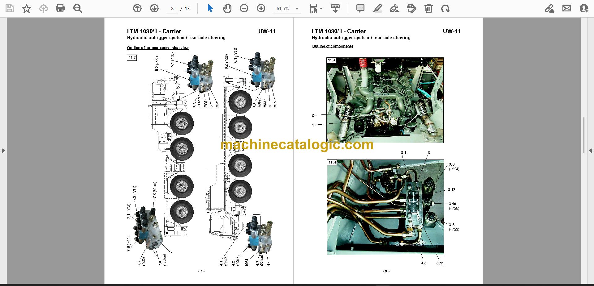
- Rebuild or replace parts shown in the component outlines, such as the hoist gear I, the restraint slewing gear, the unlocking gripper control block and the tilting cabin.
- Verify plug and fitting tightening using the ERMETO torque section, and work from the tele ram servo-valve (new version) and control block LS descriptions.
Who this is for
Crane service technicians and rental fleet mechanics who keep LTM 1080/1 units running. Also independent repair shops that get one in with no paperwork and have to sort out the hydraulic system from scratch.
FAQ
Q: What do I receive and how is it organised?
A: You get the full set: 2 manuals in 61 PDF files, 1,007 pages in total. Publication OW-08_DE is 144 pages, and Manual 2 is the main manual at 863 pages. The text is bilingual German and English, and it's searchable and copyable.
Q: Which machine does it fit?
A: The Liebherr LTM 1080/1 all terrain crane. The title wording reads "LTM 1080/1 Service Manual Contents", with superstructure component outline pages included.
Q: How does it fit my repair job?
A: If you're chasing a hydraulic fault, pulling a pump, valve block or gear, or setting things back up after a rebuild, the circuit diagrams, functional outlines and component outlines give you the reference to work from at the bench or on the crane.
Download the set, search for the circuit or component you're working on, and get the crane back on the road.
Click here to view the preview (PDF)
📘 Show Index
Table of Contents:
- Manual 2 (863 pages)
- Introduction
- Rules for prevention of accidents (UVV) during repair work
- Important safety indications
- General safety indications
- Indications on waste disposal
- Maintenance indications on exchange components
- Tightening torques, general
- Tightening torques for screwed plugs – ERMETO
- Tightening torques for swivelling screw-fitting – SWV
- Liquid sealing and locking adhesives
- General graphical symbols – hydraulic
- General graphical symbols – electric
- Crane control with electro-hydaulic load sensing (without slewing gear)
- Block diagram
- Block diagram – activation of the double variable displacement pump LPVD
- Functional principle of load sensing system with Liccon control
- Description of activation of the variable displacement pump (1+2)
- Block diagram – activation of the valve units (directional valves Barmag)
- Description of pilot control of the directional valves
- Description of activation of the valve units (working pressure)
- Functioning method of electronic load sensing control
- Activation of proportional directional valves on valve units (Ww/Hw/Tw)
- Crane hydraulics
- Circuit diagram „I“ – control oil circuit
- Functional outline for circuit diagram „I“ – control oil circuit
- Circuit diagram „II“ – oil flow with control pressure oil circuit
- Circuit diagram „III“- luffing gear
- Functional outline for circuit diagram „III“ – luffing gear
- Circuit diagram „IV“- hoist gear I
- Functional outline for circuit diagram „IV“ – hoist gear I
- Circuit diagram „Va“ – telescoping
- Functional outline for circuit diagram „Va“ – telescoping
- Circuit diagram „Vb“ – telescoping
- Functional outline for circuit diagram „Vb“ – telescoping
- emergency mode possibility
- unlocking telescopic sections by emergency mode
- Circuit diagram „VIIa“- restraint slewing gear (without pedal)
- Circuit diagram „VIIb“- released slewing gear (with pedal)
- Circuit diagram „VIII“- ballasting
- Functional outline for circuit diagram „VIII“ – ballasting
- swing-away jib
- gear pump
- Outline of components: crane hydraulics
- Outline of components: control block unlocking gripper
- Outline of components: luffing gear
- Outline of components: hoist gear I
- Outline of components: telescoping
- Outline of components: telescoping, emergency mode
- Outline of components: slewing gear (restraint)
- Outline of components: ballasting
- Outline of components: tilting cabin
- Outline of components: interlocking superstructure
- Outline of components: swing-away jib
- Control block LS (see also functional outline, pos. 8)
- Control block LS – set-up of a valve unit
- Tele ram servo-valve (new version)
- Publication OW-08_DE (144 pages)
- Simplified functional diagram
- General fundamentals on the electro-hydr. Load-Sensing system
- Principal diagram of the entire function (example: LTM 1080/1)
- Functional principal – Load Sensing with Liccon crane control
- Description of the activation of the variable displacement pump/s (Liebherr)
- Principal diagram on the activation of the valve units (Barmag/Bucher)
- Description of the activation of the valve units (Barmag/Bucher)
- Principal diagram on the Liccon Load-Sensing regulation (Liebherr)
- Description of the Liccon Load-Sensing regulation (Liebherr)
- Description (fundamentals) of the Load-Sensing regulator (Liccon-ZE 2)
- Flow diagram on test sequence, basic adjustment
- Checking and adjusting Diesel engine idling speed
- Checking pressure sensors (DA) „P and LS“ values
- Checking mechanic pump zero position (Q-min)
- Checking control oil pressure supply
- Checking/adjusting basic adjustment pump regulator
- Checking/adjusting initial current pump regulation (P1/P2)
- Flow diagram on test sequence, final current pump variation
- Checking/adjusting final current pump regulation (P1/P2)
- Procedure for modification of initial and final currents
- Test and adjustment insructions for LS control
- Adjustment/setting values on LS pump and LS control block on the LTM 1055/1
- Adjustment/setting values on LS pump and LS control block on the LTM 1060/2
- Adjustment/setting values on LS pump and LS control block on the LTM 1080/1
- Adjustment/setting values on LS pump and LS control block on the LTM 1090/2
- Adjustment/setting values on LS pump and LS control block on the LTM 1090/3
- Adjustment/setting values on LS pump and LS control block on the LTM 1100/2
- Adjustment/setting values on LS pump and LS control block on the LTM 1120/1
- Adjustment/setting values on LS pump and control block block on the LTM 1150/1
Liebherr PDF Manuals
All Crane Manuals