$ 0
0
$ 0
0

Mustang 2700V Skid Steer Loader Operator Manual (917417B)

Format: PDF (Printable Document)

File Language: English

File Size: 5.05 MB (Speed Download Link)

Brand: Mustang

Model: 2700V

Machine Type: Skid Steer Loader

Publication No.: 917417 (Rev. B)

Edition Date: March 2010

Type of Document: Operator Manual (operation, controls, safety and routine maintenance)

Searchable: Yes, text is searchable and copyable

Delivery: Instant download after payment

Categories: ,

$ 40

Share:

Mustang 2700V Skid Steer Loader Operator Manual (917417B)

Publication 917417 (Rev. B), dated March 2010, is the operator manual for the Mustang 2700V skid steer loader. It covers running the loader and looking after it, from the safety chapter through controls, operation and routine upkeep.

When I get a 2700V in for resale, the first thing a buyer asks for is the book. This one gives the new owner or rental customer the Loader Identification section, the Product and Component Plate Locations, the control and indicator symbols and the specifications in one place. Two later manuals, 50950152K (May 2021) and 50950152L (April 2022), are written for the 2700V NXT2 and 3300V NXT2 with serial numbers from 044001 and 143001 up, so the 917417 Rev. B book is the one for the plain 2700V.

What this manual helps you do

  • Start with the Safety chapter, which has the Mandatory Safety Shutdown Procedure, Safety Reminders and Potential Hazards.
  • Read the safety decal sections, which show the ANSI-style and ISO-style decals inside the ROPS/FOPS and in the engine compartment.
  • Operate the loader with the chapters on the restraint bar, safety interlock system, parking brake, joystick controls, hand/foot controls and the auxiliary hydraulic system.
  • Check the Before Starting the Engine and Fuel sections before the first start of the day.
  • Look up engine oil, the oil filter and oil pressure, then fill in the Maintenance Log and use the Troubleshooting engine diagnostic chart when something is off.

Who this is for

Dealers and used-machine buyers who need the book that goes with a 2700V. Rental fleets and owner-operators will use it to train a new operator and to keep to the maintenance log.

Print the Maintenance Log page and keep it with the machine.

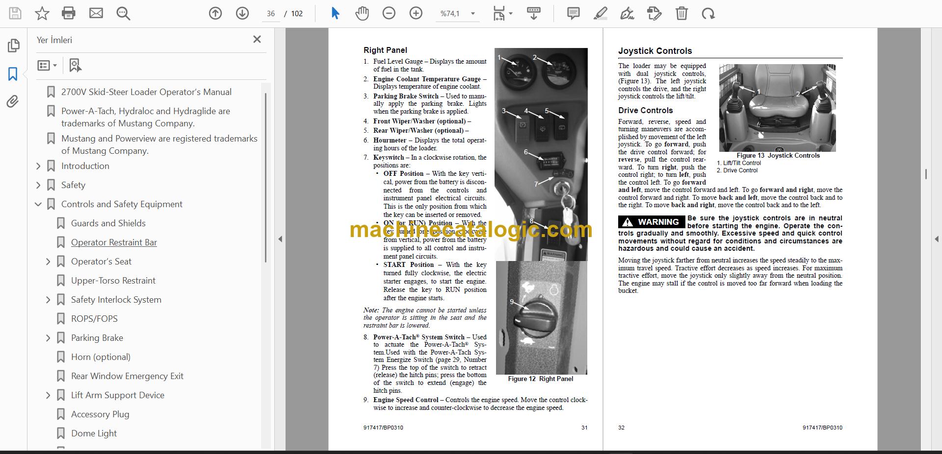
Preview of the Mustang 2700V Skid Steer Loader Operator Manual (917417B) (PDF, sample pages)

Does this manual fit your machine?

Mustang model 2700V
Machine type Skid Steer Loader
Publication No. 917417 (Rev. B)
Edition date March 2010

Check the model and serial number on your machine’s serial plate before ordering.

What’s inside

  • Troubleshooting: Engine Diagnostic Chart; Engine Diagnostic Chart (cont.); Troubleshooting
  • Torque values: Torque Specifications
  • Maintenance intervals / schedule: Maintenance Log
  • Lubrication, oils, fluids and capacities: Engine Oil; Engine Oil Filter; Engine Oil Pressure
  • Technical specifications: Specifications; Loader Specifications
  • Removal, installation and overhaul procedures: Installation; Removal
  • Adjustments and calibration: Adjustments; Adjusting Chain Tension

How this edition differs

Compared with Mustang 2700V NXT2 and 3300V NXT2 Skid Steer Loader Operator Manual (50950152K):

This manual Other edition
Publication No. 917417B 50950152K
Edition date March 2010 May 2021
Serial numbers – 2700V NXT2 SN 044001 and Up; 3300V NXT2 SN 143001 and Up
Models covered only by – 3300V

Compared with Mustang 2700V NXT2 and 3300V NXT2 Skid Steer Loader Operator Manual (50950152L):

This manual Other edition
Publication No. 917417B 50950152L
Edition date March 2010 April 2022
Serial numbers – 2700V NXT2 SN 044001 and Up; 3300V NXT2 SN 143001 and Up
Models covered only by – 3300V

Compared with Mustang 2700V and 3300V Skid Steer Loader Operator Manual:

This manual Other edition
Publication No. 917417B 50950001B
Edition date March 2010 January 2012
Serial numbers – 2700V / 2700V (EU) SN 041501 and Up
Models covered only by – 3300V

FAQ

Where do I find the safety decals and what do they cover?
The Safety Decals section has ANSI-style and ISO-style sets, each shown for inside the ROPS/FOPS and for the engine compartment.

Which section helps when the engine will not run right?
Open Troubleshooting, which has an Engine Diagnostic Chart that continues over a second page.

Does the book cover the 2700V NXT2 or the 3300V?
This book is for the 2700V. The NXT2 models and the 3300V have their own manuals, 50950152K and 50950152L, with serial numbers from 044001 (2700V NXT2) and 143001 (3300V NXT2).

Where are the chain tension adjustment and torque values?
Adjusting Chain Tension is under Adjustments, and the Torque Specifications have their own heading. Loader Specifications are listed under Specifications.
More books for this machine

📘 Show Index

Table of Contents:

  • Introduction
    • Loader Identification
    • Control/Indicator Symbols
      • Power Off
      • Power On
      • Engine Start
      • Battery Charge
      • Electrical Power
      • Worklight w/Tail Lights
      • Worklight
      • Safety Alert
      • Hazard Flasher
      • Fasten Seatbelt
      • Horn
      • Volume – Full
      • Volume – Half Full
      • Volume – Empty
      • H-L
      • High – Low
      • Neutral
      • Forward
      • Reverse
      • Parking Brake
      • Engine Air Filter
      • Engine Oil
      • Engine Oil Filter
      • Engine Oil Pressure
      • Fuel Filter
      • Engine Temperature
      • Hydraulic System
      • Hydraulic Oil Temperature
      • Hydraulic Oil Filter
      • Grease Lubrication Point
      • Glow Indicator Lamp
      • Diesel Fuel
      • Chaincase Oil
      • Clockwise Rotation
      • Counterclockwise Rotation
      • Fast
      • Slow
      • Ride Control
      • Engine Malfunction Shutdown
      • Bucket – Float
      • Bucket – Rollback
      • Bucket – Dump
      • Lift Arm – Lower
      • Lift Arm – Raise
      • Service Hours
      • Lift Point
      • Tie-Down
      • Diesel Water Separator
      • Power-A-Tach®
  • Safety
    • Mandatory Safety Shutdown Procedure
    • Safety Reminders
    • Potential Hazards
    • Safety Decals
      • New Decal Application
    • ANSI-Style Safety Decals inside the ROPS/FOPS
    • ANSI-Style Safety Decals in the Engine Compartment
    • ISO-Style (used Internationally) Safety Decals inside the ROPS/FOPS
    • ISO-Style (used Internationally) Safety Decals in the Engine Compartment
    • Product and Component Plate Locations
  • Controls and Safety Equipment
    • Guards and Shields
    • Operator Restraint Bar
    • Operator’s Seat
      • Figure 1 Operator’s Seat
    • Upper-Torso Restraint
    • Safety Interlock System
      • Hydraloc™
      • Testing the Safety Interlock System
    • ROPS/FOPS
    • Parking Brake
      • Figure 2 Parking Brake Switch
    • Horn (optional)
    • Rear Window Emergency Exit
    • Lift Arm Support Device
      • Installation
        • Figure 3 Lift Arm Support Device Engaged
      • Removal
        • Figure 4 Lift Arm Support Device Storage Location
    • Accessory Plug
    • Dome Light
    • Work Lights
    • Heater (optional)
    • Heater and Air Conditioner (optional)
      • Figure 5 Heater/ Air Conditioner Controls
    • Engine Speed Control
      • Figure 6 Engine Speed Control
      • Figure 7 Foot Throttle (Joystick control units)
    • Two-Speed Drive (optional)
    • Hydraglide™ Ride Control System
    • Attachment Mounting
      • All-Tach® Hitch
        • Figure 8 All-Tach® Hitch
      • Power-A-Tach® System
      • Indicator and Warning Lamp Display
        • Figure 9 Indicator and Warning Lamp Display
      • Indicator and Warning Lamp Display
    • Instrument Panels
      • Figure 10 Left Panel
      • Left Panel
        • Figure 11 Lower Left Panel
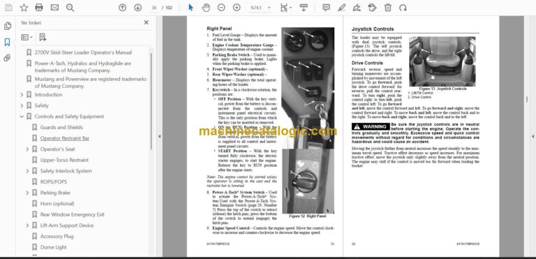
      • Right Panel
        • Figure 12 Right Panel
    • Joystick Controls
      • Figure 13 Joystick Controls
      • Drive Controls
      • Lift/Tilt Control
    • Hand/Foot Controls
      • Figure 14 Hand/Foot Controls
      • Drive Controls
      • Lift/Tilt Controls
    • Auxiliary Hydraulic System
      • Standard-Flow Auxiliary Hydraulic Control
        • Figure 15 T-Bar/Joystick Electric Auxiliary Control
      • High-Flow Auxiliary Hydraulic Control (optional)
        • Figure 16 High-Flow Auxiliary Switch
  • Operation
    • Before Starting the Engine
    • Fuel
    • Starting the Engine
    • Cold-Starting
    • Cold-Starting Procedure
    • Stopping the Loader
    • Parking the Loader
    • Jump-starting
    • Changing Attachments
      • Connecting Attachments
        • Figure 17 Manual Hitch – disengaged
      • Connecting Auxiliary Hydraulic Couplings
      • Standard-Flow Auxiliary Hydraulics
      • Removing Attachments
    • Self-Leveling (optional)
    • Using a Bucket
      • Driving over Rough Terrain
      • Driving on an Incline
      • Digging with a Bucket
        • Figure 18 Digging
      • Loading a Bucket
        • Figure 19 Loading
      • Dumping the Load onto a Pile
      • Dumping the Load into a Truck (or Hopper)
        • Figure 20 Dumping into a Truck (or Hopper)
      • Dumping the Load over an Embankment
      • Scraping with a Bucket
        • Figure 21 Scraping
      • Leveling the Ground
        • Figure 22 Leveling the Ground
    • Vibration Information
    • Vibration Measurement and Actions
      • Vibration Levels
        • Figure 23 – Vibration measurement axes
    • Highway Travel
    • Storing the Loader
    • Removing Loader from Storage
    • Storing the Loader
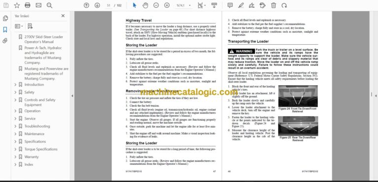
    • Transporting the Loader
      • Figure 24 Front Tie-Down/Front Retrieval
        • Figure 25 Rear Tie-Down/Rear Retrieval
    • Lifting the Loader
  • Service
    • Dealer Services
    • Replacement Parts
    • Loader Raising Procedure
      • Figure 26 Loader Properly Blocked (Tires and wheels removed to show blocks)
    • Loader Lowering Procedure
    • Engine Compartment Access
      • Figure 27 Engine Compartment Access Door and Cover
    • Tilting Back the ROPS/FOPS
      • Figure 28 ROPS/FOPS Lock Mechanism – Engaged
    • Adjustments
      • Control Handles
    • Removing Foreign Material
    • Lubrication
      • Figure 29 Service Locations
    • Chaincases
      • Checking and Adding Oil
        • Figure 30 Fill Plug Location
      • Draining Oil
        • Figure 31 Drain Plug
    • Drive Chains
      • Checking Chain Tension
      • Adjusting Chain Tension
    • Engine Air Cleaner
      • Figure 32 Dual-Element Air Cleaner
      • Access
      • Outer Element
      • Inner Element
      • Reinstallation
    • Engine Service
      • Figure 33 Engine Service Components
      • Checking Engine Mounting Hardware
      • Checking Engine Oil Level
      • Changing Engine Oil and Filter
        • Figure 34 Remote Engine Oil Drain
      • Changing Fuel Filter
      • Checking the Water Separator
    • Engine Diagnostic Chart
      • Figure 35 Flashing Patterns of the Failure Lamp
      • Engine Diagnostic Chart (cont.)
    • Hydraulic System
      • Checking Hydraulic Oil Level
        • Figure 36 Sight Gauge and Fill Tube
      • Changing Hydraulic Oil Filter
        • Figure 37 Hydraulic Oil Filter and Indicator
      • Changing Hydraulic Oil
    • Bucket Cutting Edge
    • Alternator/Fan Belt
    • Wheel Nuts
    • Lift Arm Pivots
    • Cooling System
      • Cleaning the Cooling System
    • Tires
      • Checking Tire Pressure
    • Heater/Air Conditioner Filters
    • Electrical System
      • Fuse Panel
      • Battery
  • Troubleshooting
  • Maintenance
    • Maintenance Log
  • Specifications
    • Loader Specifications
    • Standard Features
    • Optional Features
      • 16.9 ft3 (0.48 m3) Bucket w/12 x 16.5 Tires inches mm
    • Capacities and Ratings
      • 2700V
        • (213 kg)
        • (255 kg)
    • Common Materials and Densities
    • Bucket Selection
  • Torque Specifications
  • Warranty
    • MUSTANG WARRANTY SERVICE INCLUDES
    • MUSTANG WARRANTY DOES NOT INCLUDE
  • Index

Mustang PDF Manuals

Related Manuals

0
0
Your Cart
Your cart is emptyReturn to Shop