$ 0
0
$ 0
0

PAT DS 350 Load Moment Indicator Service Manual (031-300-190-046)

Format: PDF (Printable Document)

File Language: English, German

File Pages: 1,056

File Size: 41.43 MB (Speed Download Link)

File Count: 11 PDF files

Brand: PAT

Model: DS 350

Equipment Type: Load Moment Indicator

Manuals Included: 8 separate publications

Type of Document: Service Manual

Searchable: Partly, some files are scanned pages without a text layer

Delivery: Instant download after payment

Categories: ,

$ 55

Share:

PAT DS 350 Load Moment Indicator Service Manual (031-300-190-046)

The DS 350 is a load moment indicator. It watches crane loading and warns the operator as the machine nears its limits. When it throws a fault or reads wrong, the person holding the wrench needs the system documentation in front of them. That's usually a service technician or shop mechanic fixing it in-house.

What this manual helps you do

  • Trace the system from the mechanical description through the drawings and theory of operation.
  • Diagnose faults using the troubleshooting flow charts and the error code display section.
  • Check sensors and calibration against the reference guide.
  • Follow the wiring and connections drawings when chasing a bad signal or a broken run.
  • Replace a failed component with the system description beside you, so you know what you're pulling.

Who this is for

Crane service technicians, rental fleet mechanics and independent repair shops that keep LMI systems working. It also suits anyone who picked up a crane with no paperwork and needs to understand what's on it.

FAQ

Q: What do I receive and how is it organised?

A: You get the full set of 8 manuals in 11 PDF files, 1,056 pages total, in English and German. The main manual is 286 pages. The others are Publication 031-300-190-046 (64 pages), 031-300-190-076 (67 pages), 031-300-190-118 (45 pages), TCTCC 2400-3000 (123 pages), Manual 6 (188 pages), Publication 031-300-190-041 Rev J (164 pages) and DS350GM (119 pages).

Q: Which machine does it fit?

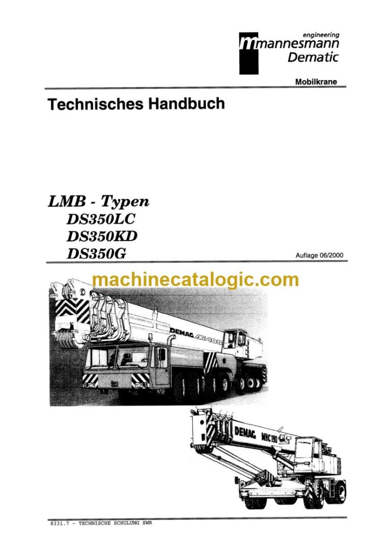
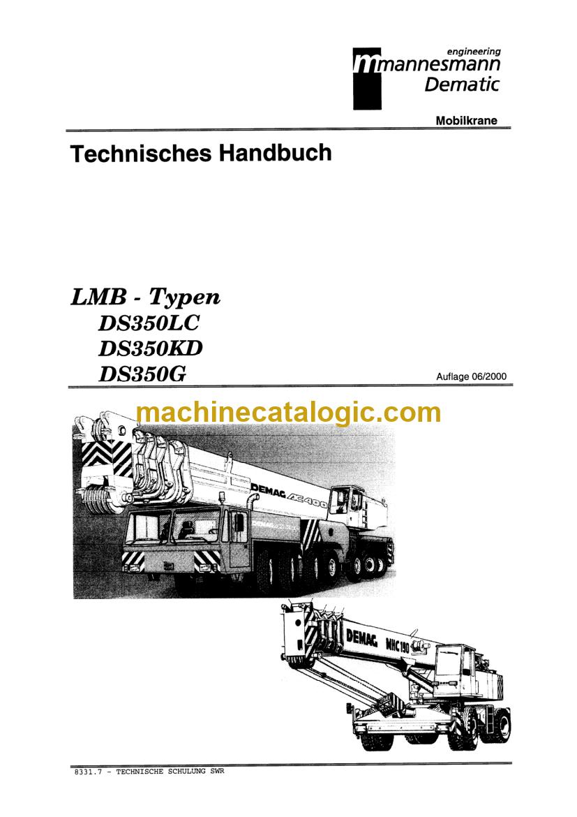
A: It's for the PAT DS 350 load moment indicator. The title reads "DS350 LMB Technical Handbook", so you can match it against the unit in front of you.

Q: How does it fit my repair job?

A: The sections run from system description and definitions through drawings, theory, flow charts, error codes and a reference guide. That's the order you work in: understand the system, find the fault, fix it.

Open the flow charts, find the error code, and get the DS 350 back in service.

Click here to view the preview (PDF)

📘 Show Index

Table of Contents:

  • Manual 4 (286 pages)
  • Publication 031-300-190-046 (64 pages)
    • SECTION 1. MECHANICAL DESCRIPTION OF THE SYSTEM
      • MECHANICAL DESCRIPTION OF THE COMPONENTS
      • MECHANICAL AND ELECTRICAL DESCRIPTION OF THE CENTRAL UNIT
      • BASIC ADJUSTMENT OF THE HARDWARE
    • SECTION 2. DEFINITIONS
    • SECTION 3. DRAWINGS
      • DRAWING 2. Cable Reel LWG208
      • DRAWING 8. Pressure Transducer Cable Assembly
      • DRAWING 9. Jumper Cable Assembly for Extension 031-300-103-541
    • SECTION 4. THEORY
      • THEORY 1. Anti-Two Block & Shutoff Circuit
      • THEORY 2. Length Measuring Channel #1
      • THEORY 3. Piston Side Pressure Measuring Channel #2
    • TROUBLESHOOTING FLOW CHARTS
      • GENERAL FLOWCHART
      • NO DISPLAY
      • ANTI TWO BLOCK PROBLEM
    • ERROR CODE DISPLAY
    • REFERENCE GUIDE
  • Publication 031-300-190-076 (67 pages)
    • GENERAL INFORMATION
    • WARNINGS
    • SYSTEM DESCRIPTION
    • GENERAL FLOW CHARTS
    • ERROR CODES
      • Operating Errors E01 through E06
      • Lockout Function Errors 07 and 08
      • Analog Input Channel Errors
    • FUNCTION LOCKOUT
    • NO DISPLAY
    • ANTI-TWO BLOCK PROBLEM
    • ANGLE SENSORS
    • LOAD READING
    • SLEWING ANGLE READING PROBLEM
    • DATA TRANSFER CENTRAL UNIT <–> CONSOLE
    • DRAWINGS AND SCHEMATICS
      • Electrical Wiring 12V Line Rider System with Slew Box 11.5 Ratio (page 1)
      • Electrical Wiring 12V Line Rider System with Slew Box 11.5 Ratio (page 2)
      • Electrical Wiring 24V Line Rider System with Slew Box 7.25 Ratio (page 1)
    • PROCEDURES
      • Procedure 1: EPROM Location and Installation
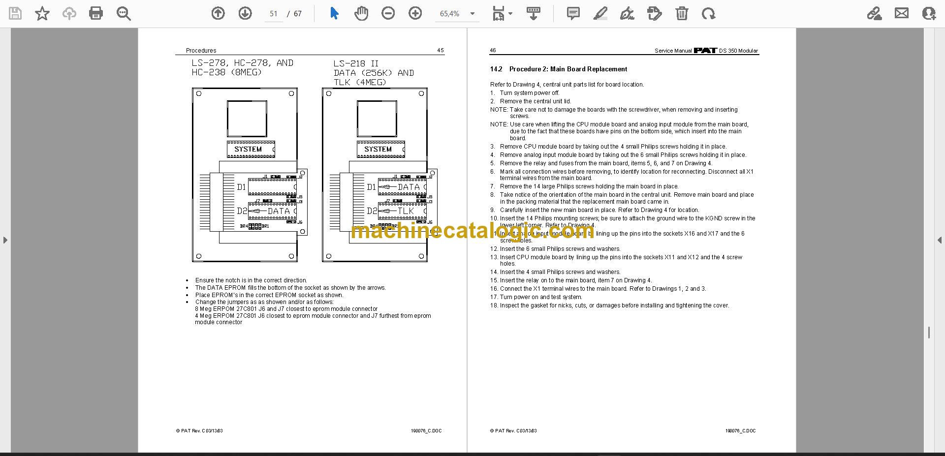
      • Procedure 2: Main Board Replacement
      • Procedure 3: Angle Sensor Adjustment/Replacement
  • Publication 031-300-190-118 (45 pages)
    • GENERAL INFORMATION
    • WARNINGS
    • SYSTEM DESCRIPTION
    • GENERAL FLOW CHARTS
    • ERROR CODES
      • Operating Errors E01 through E06
      • Lockout Function Errors 07 and 08
      • Analog Input Channel Errors
    • FUNCTION LOCKOUT
    • NO DISPLAY
    • ANTI-TWO BLOCK PROBLEM
    • ANGLE SENSORS
    • LOAD READING
    • AREA DEFINITION INDICATION PROBLEM
    • DATA TRANSFER CENTRAL UNIT <–> CONSOLE
    • DRAWINGS
      • Electrical Wiring (Drawing 1) Part 1
      • Parts List (Drawing 2)
      • Parts List (Drawing 3)
    • PROCEDURES
      • Procedure 1: EPROM Location and Installation
      • Procedure 2: Main Board Replacement
      • Procedure 3: Angle Sensor Adjustment/Replacement
  • Publication TCTCC 2400-3000 (123 pages)
    • Part 1 General Description
      • What is SLI?
      • General Notes
      • Principle of Function of SLI with Lattice Boom Cranes
    • Part 2 Central Unit
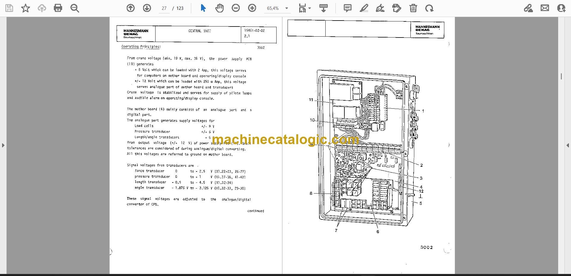
      • CPU Type DS 350 KD, Set-Up and Operation
      • Power Supply
      • Mother Boards
    • Part 3 Operating and Display Console
      • Console for Lattice Boom Cranes
    • Part 4 Angle Coverage
      • Angle Coverage
    • Part 5 Rope Tension Coverage
      • Force Transducer (Load Cell)
      • Force Coverage on Superlift
    • Part 6 Terminal Plans
      • General Notes
      • CC 2400, Superlift-Counterweight Carrier
    • Part 7 Error-Code Trouble-Shooting-Chart
      • Error-Code Numbers
      • Error Indication/Removal
    • Part 8 Glossary of Selected Terms
      • Glossary of Selected Terms
  • Manual 6 (188 pages)
    • Mechanical Description
    • Definitions
    • DS350G/GW Connections, Wiring Diagram, and Digital Inputs
    • DS350G/GW Circuit Drawings
    • DS350G/GW Central Unit P.C. Board Layout
    • DS350G/GW and DS150 Basic Adjustments and Checks
    • DS350G/GW Main Board and Transducer Replacement Procedure
    • DS350G/GW P.A.T. Electrical Diagrams
    • DS150 Connections, Wiring Diagram, and Digital Inputs
    • DS150 Circuit Drawings
    • DS150 Central Unit P.C. Board Layout
    • DS150 Main Board and Transducer Replacement Procedure
    • DS150 P.A.T. Electrical Diagrams
    • DS350G/GW Troubleshooting Guide
  • Publication 031-300-190-041 Rev J (164 pages)
    • General Information
    • Warnings
    • Flowcharts
      • GENERAL FLOWCHART
      • ERROR CODE DISPLAY
      • LEVER LOCKOUT ACTIVATED
    • Drawings
      • DRAWING 2. ELECTRICAL WIRING FOR CENTRAL UNIT TO CONSOLE
      • DRAWING 3. ELECTRICAL WIRING FOR CENTRAL UNIT TO CABLE REEL/ANTI-TWO BLOCK
      • DRAWING 4. CENTRAL UNIT – PARTS LIST
    • Procedures
      • PROCEDURE 1. STRAIN RELIEF INSTALLATION
      • PROCEDURE 2. EPROM LOCATION AND INSTALLATION
      • PROCEDURE 3. MAIN BOARD REPLACEMENT
    • Theory
      • THEORY 1. OPERATION OF BOOM LENGTH SENSOR
      • THEORY 2. OPERATION OF PISTON SIDE LOAD SENSOR
      • THEORY 3. OPERATION OF ROD SIDE LOAD SENSOR
    • SYSTEM DESCRIPTION
    • GENERAL FLOW CHARTS
    • ERROR CODES
      • Operating errors E01 trough E06
      • Lockout function errors E07 an E08
      • Analog input channel Errors
    • FUNCTION LOCKOUT
    • NO DISPLAY
    • ANTI-TWO (A2B) PROBLEM
    • ANGLE SENSORS
    • LOAD READING
    • AREA DEFINITION INDICTION PROBLEM
    • DATA TRANSFER CENTRAL UNIT <—> CONSOLE
    • ANTI-TWO BLOCK PROBLEM
    • AREA DEFINITION INDICATION PROBLEM
    • DATA TRANSFER CENTRAL UNIT <–> CONSOLE
  • Publication DS350GM (119 pages)
    • GENERAL INFORMATION
    • WARNINGS
    • FLOWCHARTS
      • GENERAL FLOWCHART
      • ERROR CODE DISPLAY
      • LEVER LOCKOUT ACTIVATED
    • DRAWINGS
      • DRAWING 2. ELECTRICAL WIRING FOR CENTRAL UNIT TO CONSOLE
      • DRAWING 3. ELECTRICAL WIRING FOR CENTRAL UNIT TO CABLE REEL/ANTI-TWO BLOCK
      • DRAWING 4. CENTRAL UNIT – PARTS LIST
    • PROCEDURES
      • PROCEDURE 1. STRAIN RELIEF INSTALLATION
      • PROCEDURE 2. EPROM LOCATION AND INSTALLATION
      • PROCEDURE 3. MAIN BOARD REPLACEMENT
    • THEORY
      • THEORY 1. OPERATION OF BOOM LENGTH SENSOR
      • THEORY 2. OPERATION OF PISTON SIDE LOAD SENSOR
      • THEORY 3. OPERATION OF ROD SIDE LOAD SENSOR

PAT PDF Manuals

All Crane Manuals

Related Manuals

0
0
Your Cart
Your cart is emptyReturn to Shop