Format: PDF (Printable Document)
File Language: English
File Pages: 37
File Size: 2.10 MB (Speed Download Link)
File Count: 1 PDF file
Brand: PAT
Model: MC320
Equipment Type: Load Moment Indicator
Book No: 031-300-190-121
Type of Document: Service Manual
Searchable: Yes, text is searchable and copyable
Delivery: Instant download after payment
$ 55
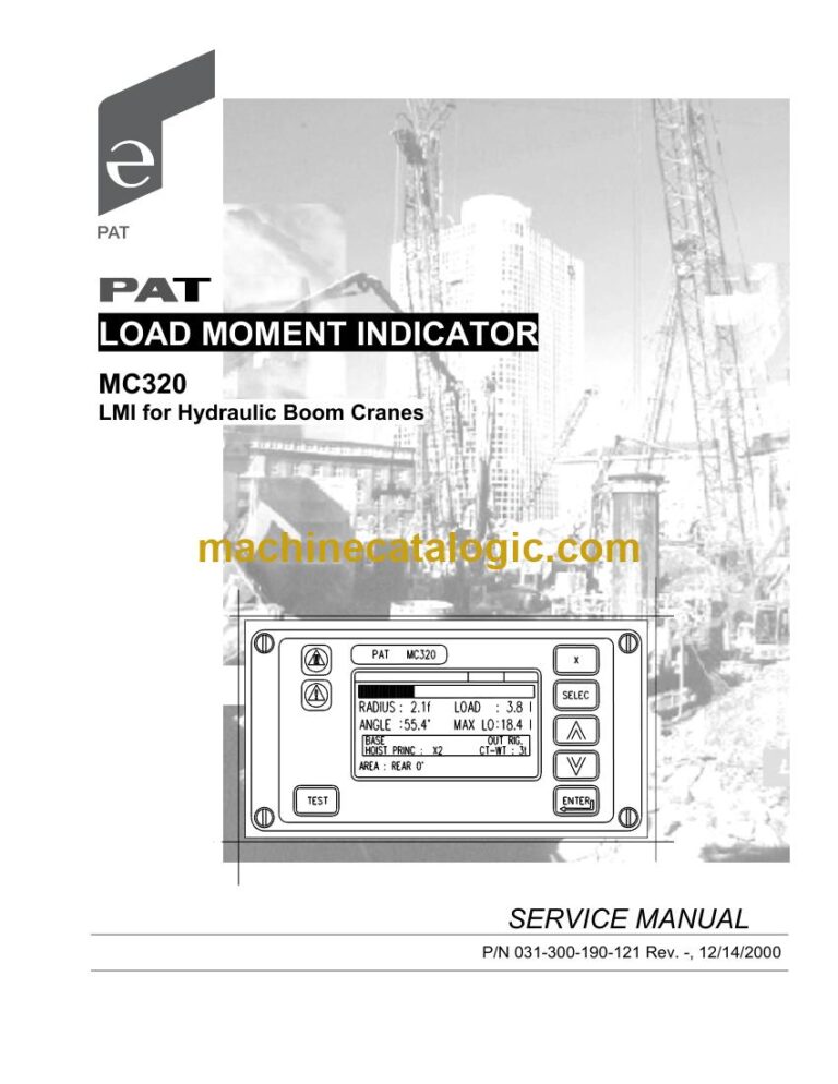
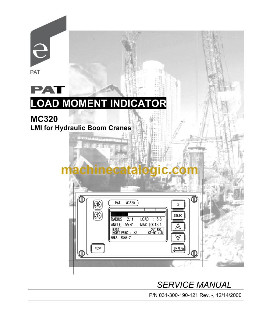
The MC320 is a load moment indicator for hydraulic boom cranes. It monitors crane loading using length and angle sensors, a cable reel, and a console that shows the operator what's happening and locks out the lever when limits are reached. Technicians open the service manual when a unit needs adjusting, a console shows nothing, or a reading is off. It's the book to have on the bench before you touch the console or cable reel.
What this manual helps you do
Who this is for
A crane service technician or rental fleet mechanic who has an MC320 on a hydraulic boom crane and needs to fix it in-house. Also useful to independent repair shops and dealer technicians who see these systems come in with no paperwork.
FAQ
Q: What do I receive and how is it organised?
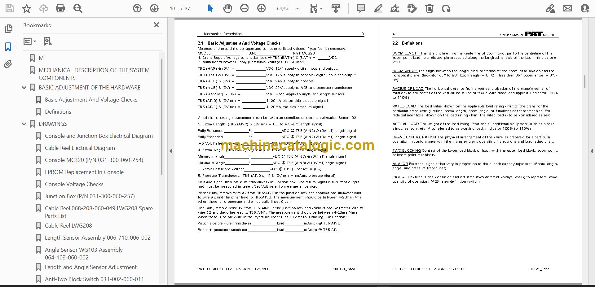
A: You get one PDF file, 37 pages, in English, with searchable text. It runs from definitions and adjustments through the electrical diagrams to the troubleshooting flowcharts.
Q: Which machine does it fit?
A: It is written for the PAT MC320 LMI for Hydraulic Boom Cranes, publication number 031-300-190-121. Check that number against the title wording on your unit's documentation.
Q: How does it fit the job I'm doing?
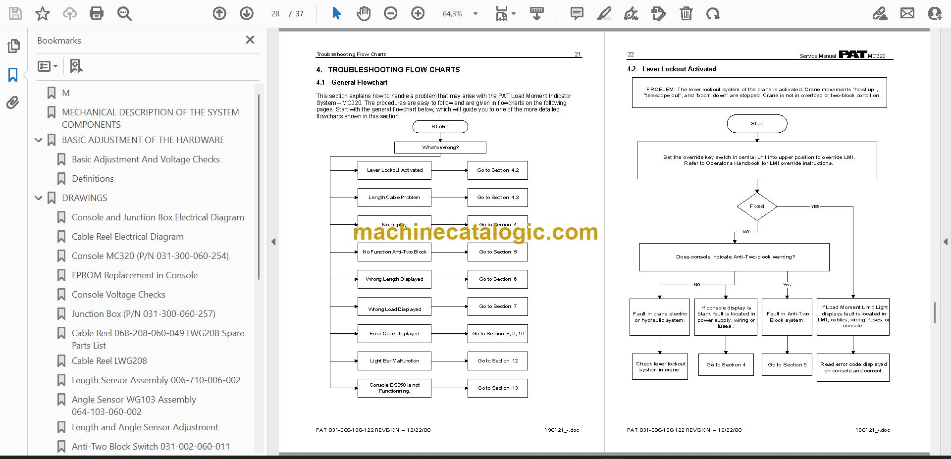
A: If you're chasing a fault, start at the general flowchart and work to the matching problem section. If you're adjusting or replacing parts, go to the sensor, cable reel and EPROM sections. The wiring diagrams cover the console, cable reel and each swingaway extension type.
This is the complete manual. Download it, open the flowchart, and you can start tracing the fault at the crane.
Click here to view the preview (PDF)