Format: PDF (Printable Document)
File Language: English
File Pages: 447
File Size: 33.84 MB (Speed Download Link)
Brand: Sumitomo
Model: SH75X-3B
Type of Document: Shop Manual & Service Text
$ 45
About This Shop Manual
Safety ……………………………………………………………………………………………………………..1
Introduction……………………………………………………………………………………………………..2
Using Technical Information
Symbols……………………………………………………………………………………………………….3
Precautions for Use
General Preparation for Disassembly ……………………………………………………………..15
General Cautions for Assembly ……………………………………………………………………..17
General Cautions When Performing Inspections………………………………………………21
Tightening Torque
Tightening Bolts and Nutsc……………………………………………………………………………22
Retightening Torque Table…………………………………………………………………………….22
Numerical Conversion Table ………………………………………………………………………….23
Specifications
Overall View
Equipment Layout………………………………………………………………………………………….1
Overall……………………………………………………………………………………………………..1
Operator’s Cab………………………………………………………………………………………….2
Main Equipment Table
Lower Assembly Diagram (overall) …………………………………………………………………..3
1. SH75X-3B (Mono-boom / Offset-boom) …………………………………………………..3
Lower Component …………………………………………………………………………………………4
1. Travel Unit……………………………………………………………………………………………4
2. Take-up Roller ……………………………………………………………………………………..4
3. Upper Roller ………………………………………………………………………………………..4
4. Lower Roller ………………………………………………………………………………………..4
5. Recoil Spring……………………………………………………………………………………….5
6. Shoe …………………………………………………………………………………………………..5
Upper Component …………………………………………………………………………………………6
1. Swing Unit …………………………………………………………………………………………..6
Engine-related ………………………………………………………………………………………………7
1. Engine ………………………………………………………………………………………………..7
2. Muffler ………………………………………………………………………………………………..8
3. Air Cleaner (double element)………………………………………………………………….8
4. Radiator………………………………………………………………………………………………8
Fuel Tank ……………………………………………………………………………………………………..9
Hydraulic Oil Tank………………………………………………………………………………………..11
Hydraulic Device………………………………………………………………………………………….13
1. Hydraulic Pump ………………………………………………………………………………….13
Control-related…………………………………………………………………………………………….14
1. Control Valve ……………………………………………………………………………………..14
2. Solenoid Valve (3 stack) ………………………………………………………………………14
3. Remote Control Valve………………………………………………………………………….15
4. Remote Control Valve Characteristic Diagram………………………………………..17
5. Center Joint ……………………………………………………………………………………….20
Backhoe Attachment…………………………………………………………………………………….21
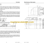
1. Cylinder …………………………………………………………………………………………….21
2. Attachments ………………………………………………………………………………………23
Oil and Filters
Method of Use for Fuel and Lubricating Oil According to Air Temperature……………24
Fuel and Oil…………………………………………………………………………………………….24
Anti-freeze………………………………………………………………………………………………24
Sumitomo Genuine Parts………………………………………………………………………………24
Engine Fuel and Filter Maintenance……………………………………………………………….25
Fuel Used……………………………………………………………………………………………….25
Filter and Maintenance …………………………………………………………………………….26
Consumable Parts ……………………………………………………………………………………….27
SH75X-3B Oil Feeding and Element Replacement …………………………………………..28
Replacement Times for Hydraulic Oil and Filters When Using the Breaker ………….31
Performances
Lifting Capacity………………………………………………………………………………………. 1
Precautions for Lifting Loads with the Hydraulic Excavator ………………………………….1
Lifting Capacities SH75X-3B (Mono-boom with blade)……………………………………….2
1. Standard Arm (1.71 m), 450 Grouser shoe (Blade down)…………………………..2
2. Standard Arm (1.71 m), 450 Grouser shoe (Blade up) ………………………………3
3. Long Arm (2.12 m), 450 Grouser shoe (Blade down) ………………………………..4
4. Long Arm (2.12 m), 450 Grouser shoe (Blade up) …………………………………….5
Lifting Capacities SH75X-3B (Offset-boom with blade) ……………………………………….6
1. Standard Arm (1.75 m), 450 Grouser shoe (Blade down)…………………………..6
2. Standard Arm (1.75 m), 450 Grouser shoe (Blade up) ………………………………7
3. Long Arm (2.10 m), 450 Grouser shoe (Blade down) ………………………………..8
4. Long Arm (2.10 m), 450 Grouser shoe (Blade up) …………………………………….9
Hydraulic Pump Control Diagram……………………………………………………………. 10
P-Q Diagram……………………………………………………………………………………………….10
Disassembling and Maintenance Instructions for Main Body
Maintenance Procedures
Lower Unit Path Block Diagram……………………………………………………………………….1
Main Parts Tightening Torque………………………………………………………………………….2
Bolt and Nut Tightening ……………………………………………………………………………..2
Inspection and Maintenance……………………………………………………………………………3
Retightening Torque Table ………………………………………………………………………….3
Lower Unit
Track Shoe……………………………………………………………………………………………………6
1. Removal Procedure………………………………………………………………………………7
2. Installation Procedure……………………………………………………………………………8
3. Track Link Replacement Procedure…………………………………………………………9
Travel Unit …………………………………………………………………………………………………..10
1. Assembly Precautions …………………………………………………………………………10
2. Removal Procedure…………………………………………………………………………….11
3. Installation Procedure………………………………………………………………………….12
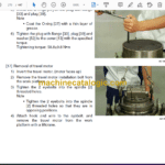
Recoil Spring Assembly………………………………………………………………………………..13
1. Removal Procedure…………………………………………………………………………….14
2. Installation Procedure………………………………………………………………………….15
Upper Roller ……………………………………………………………………………………………….16
1. Removal Procedure…………………………………………………………………………….17
2. Installation Procedure………………………………………………………………………….18
Lower Roller………………………………………………………………………………………………..19
1. Removal Procedure…………………………………………………………………………….20
2. Installation Procedure………………………………………………………………………….21
Center Joint ………………………………………………………………………………………………..22
1. Removal Procedure…………………………………………………………………………….23
2. Installation Procedure………………………………………………………………………….24
Upper Unit
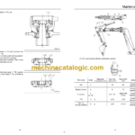
Swing Unit ………………………………………………………………………………………………….25
Engine ……………………………………………………………………………………………………….28
Hydraulic Pump …………………………………………………………………………………………..30
Control Valve ………………………………………………………………………………………………31
Remote Control Valve…………………………………………………………………………………..32
Operator’s Cab ……………………………………………………………………………………………35
Disassembling and Maintenance Instructions for Main Body
Attachments
Removal and Installation of Bucket Cylinder ……………………………………………………..1
1. Removal Procedure………………………………………………………………………………1
2. Installation Procedure……………………………………………………………………………3
Removal and Installation of Arm Cylinder………………………………………………………….5
1. Removal Procedure………………………………………………………………………………5
2. Installation Procedure……………………………………………………………………………7
Removal and Installation of Boom Cylinder……………………………………………………….9
1. Removal Procedure………………………………………………………………………………9
2. Installation Procedure………………………………………………………………………….11
Take-up Roller
Assembly and Disassembly Procedures …………………………………………………………13
1. Configuration Diagram…………………………………………………………………………13
2. Tools and Jigs…………………………………………………………………………………….13
3. Disassembly Procedures……………………………………………………………………..14
4. Assembly Procedures………………………………………………………………………….16
Assembly Diagram……………………………………………………………………………………….19
Upper Roller
Disassembly and Assembly Procedures …………………………………………………………20
1. Configuration Diagram…………………………………………………………………………20
2. Tools and Jigs…………………………………………………………………………………….20
3. Disassembly Procedures……………………………………………………………………..21
4. Assembly Procedures………………………………………………………………………….23
Assembly Diagram……………………………………………………………………………………….26
Lower Roller
Assembly and Disassembly Procedures …………………………………………………………27
1. Configuration Diagram…………………………………………………………………………27
2. Tools and Jigs…………………………………………………………………………………….27
3. Disassembly Procedures……………………………………………………………………..28
4. Assembly Procedures………………………………………………………………………….31
Assembly Diagram……………………………………………………………………………………….34
Grease Cylinder
Assembly and Disassembly Procedures …………………………………………………………35
1. Configuration Diagram…………………………………………………………………………35
2. Tools and jigs……………………………………………………………………………………..35
3. Disassembly Procedures……………………………………………………………………..36
4. Assembly procedure……………………………………………………………………………37
Assembly Diagram……………………………………………………………………………………….39
Center Joint
Assembly and Disassembly Procedures …………………………………………………………40
1. Configuration Diagram…………………………………………………………………………40
2. Tools and Jigs…………………………………………………………………………………….41
3. Disassembly Procedures……………………………………………………………………..42
4. Assembly Procedures………………………………………………………………………….44
Assembly Diagram……………………………………………………………………………………….46
