The AML-L2C load moment indicator watches crane loading and tells the operator when the machine is getting close to its limit. When it throws an error, reads wrong or needs a part swapped, somebody has to open it up. That's who reaches for a service manual: a technician fixing the unit in-house, or a shop that got a crane with no paperwork.
What this manual helps you do
- Diagnose faults using the error message section of the manual.
- Follow the adjustment mode and maintenance mode procedures step by step.
- Verify which adjustments are required after AML system parts are replaced.
- Trace input/output signals for the crane models listed in the manual, including GR-450-1/GR-500-1, TR-300-4/GR-300-1, TR-150-4/GR-150-1, GR-600-1/GR-800-1 and GT-900-1.
- Replace the clock battery and fuses, and take the AML main unit apart.
Who this is for
Crane service technicians, rental fleet mechanics and independent repair shops that work on Tadano cranes fitted with the AML system. It's also useful for dealer technicians who need adjustment values and detector checks at the bench.
FAQ
Q: What do I receive and how is it organised?
A: You get the set: 2 PDF files, 328 pages in total, in English. Publication W301-0139E is the main manual at 242 pages, and Publication W301-0131E adds 86 pages. The text is searchable and can be copied.
Q: Which machine does it fit?
A: It's the service manual for the Tadano AML-L2C load moment indicator. The main manual's publication number is W301-0139E. The signal sections are laid out by crane model, so you can go straight to yours.
Q: How does it fit the job I'm doing?
A: If you're chasing an error message, setting up after a part swap, or checking detectors, the sections are arranged for that. You'd expect to find an adjustment value table, fuse information and main unit disassembly alongside the operation and maintenance sections.
Keep it on the bench next to the unit and work through the adjustment and error sections as you go.
Click here to view the preview (PDF)
📘 Show Index
Table of Contents:
- Publication W301-0139E (242 pages)
- Foreword
- Components of the AML Main Unit
- Panel
- Internal view and name plate
- Internal block diagram
- Input/Output Signals of the AML System (GR-450-1/GR-500-1)
- Input/Output Signals of the AML System (TR-300-4/GR-300-1)
- Input/Output Signals of the AML System (TR-150-4/GR-150-1)
- Input/Output Signals of the AML System (GR-600-1/GR-800-1)
- Diagram of the AML System (GT-900-1)
- Input/Output Signals of the AML System (GT-900-1)
- [OPERATION]
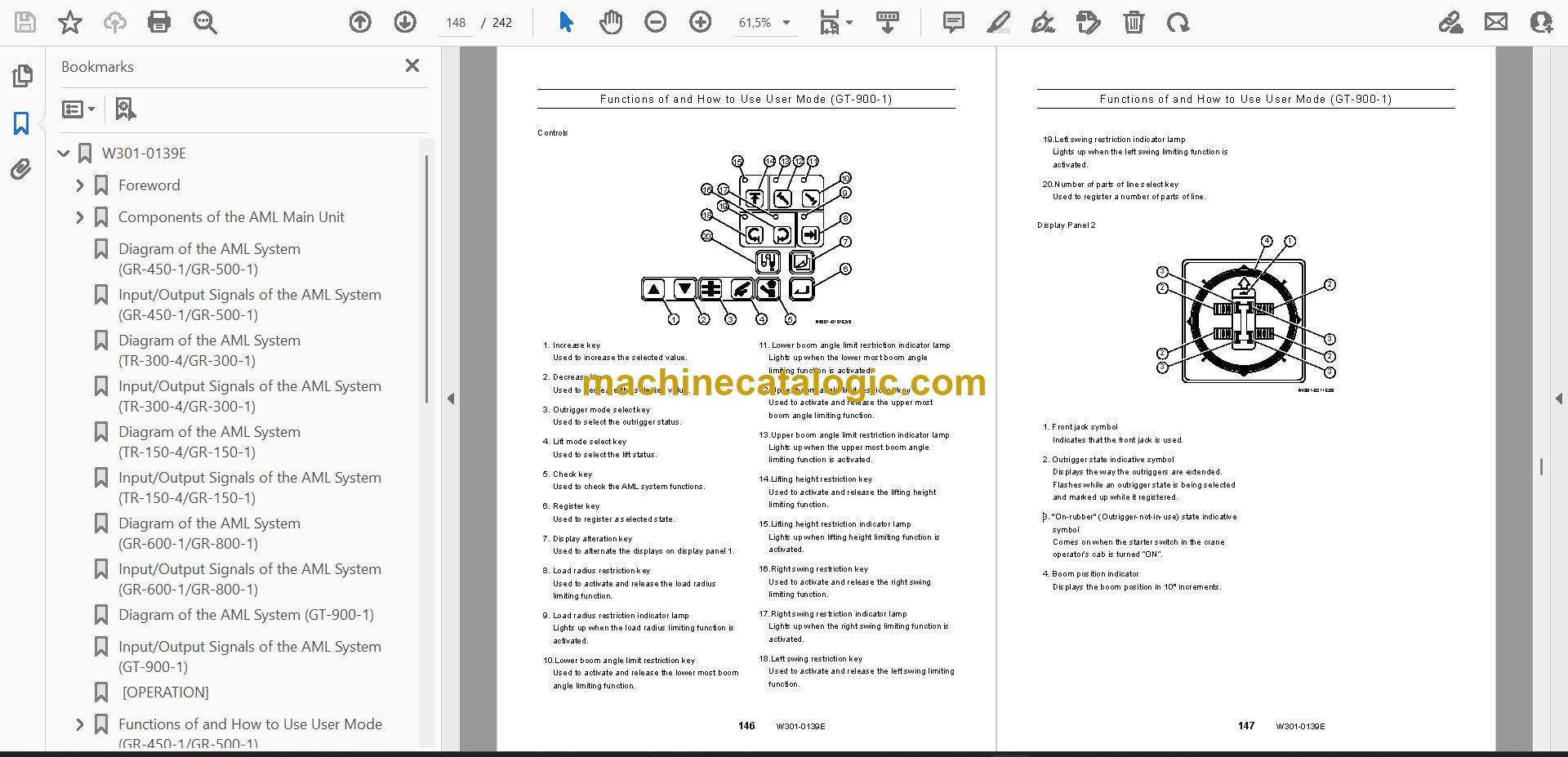
- Functions of and How to Use User Mode (GT-900-1)
- Mode Structure
- Configuration and Functions of the AML System
- Names and Functions of AML Main Unit Parts
- [ADJUSTMENT AND MAINTENANCE]
- General: Adjustment Mode and Maintenance Mode
- Keys and Switches for Adjustment and Maintenance
- Mode Structure and Menu
- Method of Shifting Modes
- Required Adjustment After AML System Parts Replacement
- Functions of and How to Use Adjustment Mode
- Adjustment Procedures
- Other Functions and How to Use Them
- Functions of and How to Use Maintenance Mode
- Program Version Display
- Data ID Number Display
- Di Check
- Error Message
- Display of Error Message
- How to Read the Error Message
- How to Read the Error History
- Disassembly of AML Main Unit
- Removing Front Panel/Display Board
- Removing Rear Panel/Connector Board/Current Output Board
- Removing CPU Board/Analog Board /Power Board
- [INFORMATION AND DATA]
- Adjustment Value Table
- Checking the Detectors (GT-900-1)
- Boom Length Detector
- Boom Angle Detector
- Swing Angle Detector
- Fuses
- Replacing the Clock Battery
- History of revision
- Publication W301-0131E (86 pages)
- Introduction
- Components of the Load Moment Indicator (AML-L2C) Main Unit
- Diagram of the Load Moment Indicator (AML-L2C) System
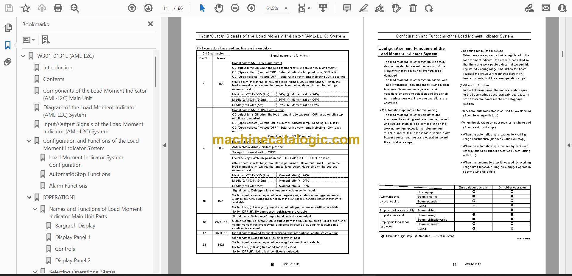
- Input/Output Signals of the Load Moment Indicator (AML-L2C) System
- Configuration and Functions of the Load Moment Indicator SYstem
- Load Moment Indicator System Configuration
- Automatic Stop Functions
- Alarm Functions
- [OPERATION]
- Names and Functions of Load Moment Indicator Main Unit Parts
- Selecting Operational Status
- Load Moment Indicator Pre-operational Inspection
- [ADJUSTMENT AND MAINTENANCE]
- General: Adjustment Mode and Maintenance Mode
- Functions of and How to Use Adjustment Mode
- Functions of and How to Use Maintenance Mode
- [INFORMATION AND DATA]
- Adjustment Value Table
- Multiplex Data Transmitter (MDT) Input/Output Nos. and Corresponding Signals
- Checking the Detectors
Tadano PDF Manuals
All Crane Manuals