$ 0
0
$ 0
0

Tadano TM-35100-1 Truck Crane Full Manual (Operator, Parts, Service)

Format: PDF (Printable Document)

File Language: English, Spanish

File Pages: 3,132

File Size: 371.90 MB (Speed Download Link)

File Count: 23 files (22 PDF)

Brand: Tadano

Model: TM-35100-1

Equipment Type: Truck Crane

Manuals Included: Operator Manual (1,704 pages), Parts Manual (757 pages), Service Manual (448 pages), Load charts (1 file), Technical data (1 file)

Publication No.: Operator Manual: TM-35100-1-O1(U)-1E, TM-35100-1-O1(U)-3E; Parts Manual: TM-35100-1-P1(U)-2EJ, TM-35100-1-P1(U)-1EJ; Service Manual: TM-35100-1-S1(U)-1E, W301-0361E

Serial No.: 291072 and up, 291077, 291071 and up

Type of Document: Full Manual Set

Searchable: Partly, some files are scanned pages without a text layer

Delivery: Instant download after payment

Categories: ,

$ 100

Share:

Tadano TM-35100-1 Truck Crane Full Manual (Operator, Parts, Service)

A Tadano TM-35100-1 is a boom truck crane. It's driven to site, set on outriggers, and used to pick and place loads with the boom. A rental fleet manager who wants every document for this model in one place, so operators, mechanics and the parts desk all work from the same set, is the person this download is built for.

What this manual set helps you do

  • Operate the crane safely by following the operator manual's safety rules, crane operation procedure, load moment indicator (AML) instructions and PTO warm-up steps.
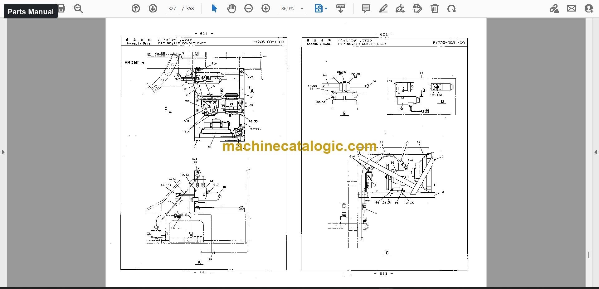
  • Order parts correctly from the parts manual's exploded views of the hydraulic system, carrier, controls and mounting parts.
  • Repair and adjust the outrigger, swing, boom elevating, winch, telescoping and safety systems using the service manual.
  • Read the load charts before planning a lift.
  • Check machine details in the technical data and the assembly and installation file.

Who this is for

A rental fleet manager can hand the operator manual to drivers, the service manual to the shop, and the parts manual to the parts desk, all for the same machine. A workshop taking on a TM-35100-1 can use the same set for repairs and part orders.

FAQ

Q: What do I receive and how is it organised?

A: One download with 23 files (22 PDF) and 3,132 PDF pages in total. The operator manual is 1,704 pages in 15 files, in English and Spanish. The parts manual is 757 pages in 2 files, and the service manual is 448 pages in 2 files, both in English. Load charts (36 pages), technical data (41 pages), assembly and installation (146 pages) and one file of other documents are included too.

Q: Which machine does it fit?

A: The Tadano TM-35100-1 truck crane. The main manual cover shows serial number 291072 and up, so check your machine's plate against that.

Q: How does it fit my job?

A: If you run, repair or supply parts for this crane, the three manuals cover those jobs: operation, parts ordering and repair. You'd keep one set per machine instead of collecting separate files.

Download it and give each person on the crane the manual for their part of the work.

Does this manual fit your machine?

Model Serial No.
TM-35100-1 291072 and up

The serial number shown is the one printed on the manual cover. Check the model and serial number on your machine's data plate before ordering.

📘 Show Index

Table of Contents:

Operator Manual Table of Contents

1,704 pages, 15 files

  • Publication TM-35100-1-O1(U)-3E / Serial No. 291072 and up (506 pages)
    • Safety Rules (Crane Operation)
    • Safety Rules (Basket Operation)
    • Safety Rules (Radio-control System)
    • Warning Labels
    • Preface
    • Servicing and Ordering Parts
    • Components
    • Layout of Controls
    • Terminology
    • [CRANE OPERATION]
    • Crane Operation Procedure – Summary
    • How to Read the Performance Data Plate
    • Load Moment Indicator (AML)
    • Other Safety Devices
    • Operating the PTO and Warming Up the Machine
    • Outriggers
    • Crane Operator's Cab
    • Starting and Stoping the Engine
    • Acceleration
    • Hoisting
    • Telescoping the Boom
    • Elevating the Boom
    • Swinging the Boom
    • Reeving Wire Rope
    • Jib
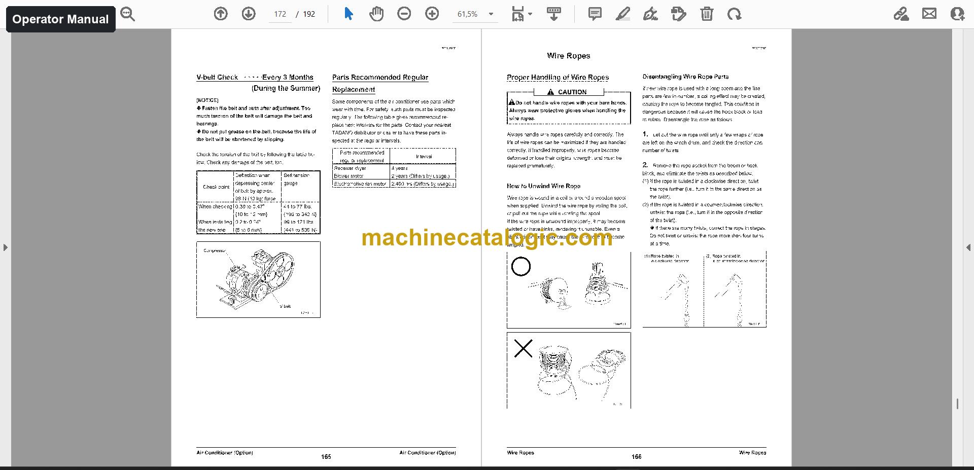
    • Air Conditioner (Option)
    • Equipment Inside the Cab
    • [BASKET OPERATION (OPTION)]
    • Basket Operation Procedure – Summary
    • Radio-control
    • Basket
    • Emergency Procedure
    • [INSPECTION AND MAINTENANCE]
    • Inspection and Maintenance
    • Pre-Operational and Periodic Inspection
    • Safety Parts Requiring Regular Replacement
    • Greasing
    • Gear Oil
    • Hydraulic System
    • Swing System
    • Accelerator System
    • Electrical System
    • Wire Ropes
    • [INFORMATION AND DATA]
    • Major Specifications
    • Oils and Greases
    • Consumable Parts
    • Hand Signals
  • Serial No. 291072 (276 pages)
  • Publication TM-35100-1-O1(U)-1E / Serial No. 291077 (414 pages)

    Same chapters as the edition above (another edition or language of this manual).

  • Manual 3 (253 pages)

    Same chapters as the edition above (another edition or language of this manual).

  • Manual 4 (255 pages)

    Same chapters as the edition above (another edition or language of this manual).

Parts Manual Table of Contents

757 pages, 2 files

  • Publication TM-35100-1-P1(U)-1EJ / Serial No. 291071 and up (358 pages)
    • Hydraulic Pressure Generator System
    • Elevating System
    • Indication Plates
    • Accessories Tools
    • Mounting Parts
    • Carrier
    • Piping Radiator
    • Control
    • Outrigger System
    • Swing System
    • Piping Swing
    • Cylinder Elevating
    • Piping Elevating
    • Winch System
    • Piping Winch Main
    • Mounting Winch Main
    • Telescoping System
    • Boom
    • Cylinder Telescoping
    • Piping Telescoping
  • Publication TM-35100-1-P1(U)-2EJ / Serial No. 291071 and up (399 pages)

Service Manual Table of Contents

448 pages, 2 files

  • Publication TM-35100-1-S1(U)-1E / Serial No. 291072 and up (321 pages)
    • Foreword
      • Applicable spec. No
      • Separate service manual
      • Outline of specifications
    • (B) Hydraulic Power Generating System
      • B-1 Hydraulic Power Generating System
      • B-2 Hydraulic Pump
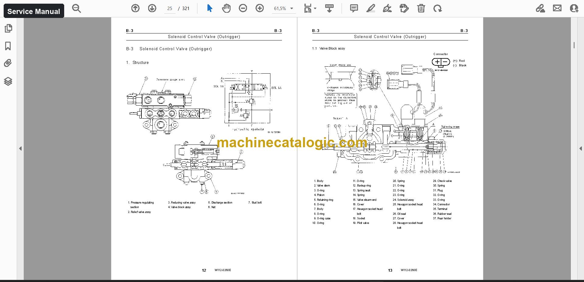
      • B-3 Solenoid Control Valve (Outrigger)
    • (C) Outrigger System
      • C-1 Outrigger System
      • C-2 Jack Cylinder
      • C-3 Pilot check Valve (Jack Cylinder Retracting Prevention)
    • (D) Swing System
      • D-1 Swing System
      • D-2 Swing Assembly
      • D-3 Hydraulic Pilot Control Valve (Swing)
    • (E) Boom Elevating System
      • E-1 Elevating System
      • E-2 Elevating Cylinder
      • E-3 Counterbalance Valve (Elevating)
    • (F) Winch System
      • F-1 Winch System
      • F-2 Winch
      • F-3 Hydraulic Motor and Counterbalance Valve
    • (G) Telescoping System
      • G-1 Telescoping System
      • G-2 Boom (Four-Section Boom)
      • G-4 Telescoping Cylinder
    • (H) Safety System
      • H-1 Safety System
      • H-2 Boom Length and Angle Detector
      • H-3 Outrigger Extension Length Detector
    • (L) Control System
      • L-1 Control System
      • L-2 Remote Control Valve (Lever)
      • L-3 Remote Control Valve (Pedal)
    • (V) Radio Control System
      • V-1 Configurations of Radio-control System
      • V-2 Radio-control Valve
      • V-3 Acclerator Cylinder
    • (Y) Data, Adjustment and Checks
      • Y-1 Hydraulic Pressure Setting Table
      • Y-2 Air Bleeding Procedure
      • Y-3 Electric Switch Adjustment
    • (Z) System Diagrams
      • Z-1 Hydraulic Circuit
      • Z-2 Electric Circuit
      • Z-3 Location of Hydraulic Parts (Upper)
    • History of revision
  • Publication W301-0361E / Serial No. 291067 and up, 291072 and up (127 pages)
    • Foreword
      • Applicable spec. No
    • Components of the AML Main Unit
      • Panel
      • Internal view and name plate
      • Internal block diagram
    • Diagram of the AML System (GS-300-1)
    • Input/Output Signals of the AML System (GS-300-1)
    • Diagram of the AML System (TM-3500-1)
    • Input/Output Signals of the AML System (TM-3500-1)
    • [OPERATION]
    • Functions of and How to Use User Mode (GS-300-1)
      • Mode Structure
      • Configuration and Functions of theAML System
      • Names and Functions of AML Main Unit Parts
    • Functions of and How to Use User Mode (TM-3500-1)
      • Mode Structure
      • Configuration and Functions of theAML System
      • Names and Functions of AML Main Unit Parts
    • [ADJUSTMENT AND MAINTENANCE]
    • General: Adjustment Mode and Maintenance Mode
      • Keys and Switches for Adjustment and Maintenance
      • Mode Structure and Menu
      • Method of Shifting Modes
    • Required Adjustment After AML System Parts Replacement
    • Functions of and How to Use Adjustment Mode
      • Adjustment Procedures
      • Adjustment Initialization
      • Capacity Setting
    • Functions of and How to Use Maintenance Mode
      • Program Version Display
      • Data ID Number Display
      • Di Check
    • Error Message
      • Display of Error Message
      • How to Read the Error Message
      • How to Read the Error History
    • [INFORMATION AND DATA]
      • Adjustment Value Table
    • Checking the Detectors(GS-300-1)
      • Boom Length Detector
      • Boom Angle Detector
      • Swing Angle Detector
    • Checking the Detectors(TM-3500-1)
      • Boom Length Detector
      • Boom Angle Detector
      • Swing Angle Detector
    • Fuses
    • Replacing the Clock Battery
    • History of revision

Also in this set

  • Load charts (1 file, 36 pages)
  • Technical data (1 file, 41 pages)
  • Assembly and installation (1 file, 146 pages)
  • Other documents (1 file)

Tadano PDF Manuals

All Crane Manuals

Related Manuals

0
0
Your Cart
Your cart is emptyReturn to Shop