Out on a job, this 435 compact excavator is what you use for trenching, footings, and tight cleanup work around buildings and corrals. The service manual is what you grab when something quits swinging, a track motor gets weak, or a boom cylinder starts leaking and you don't want to guess. In my experience, anyone who actually turns wrenches on these machines ends up needing this manual once the warranty is long gone. You're trying to get in, fix it right over a weekend, and get the machine back digging on Monday.
What this manual helps you do
- Diagnose no-start and hard-start issues on the small diesel engine, then follow proper repair and adjustment steps
- Trace hydraulic problems like weak boom, slow travel, or creeping cylinders and check pressures at the right test ports
- Follow teardown and reassembly procedures for pumps, drive motors, and cylinders when you're resealing or rebuilding
- Troubleshoot electrical problems using wiring diagrams, from dead joysticks to bad sensors and intermittent shorts
- Set and verify key adjustments after repairs so swing, travel, and auxiliary hydraulics work like they should
Who this is for
This manual is for anyone responsible for keeping a Bobcat 435 running: small contractors, farm and ranch owners, shop mechanics, and rental fleets. If you only need to know how to run the controls or daily grease points, you want the operator's handbook instead, not this service manual.
FAQ
Q: Is this a searchable PDF and are the wiring diagrams readable?
A: Yes, these manuals are normally searchable PDFs and the wiring diagrams are laid out so you can zoom in and read connector and wire labels.
Q: Will this cover my 435 if my serial number is between AACD11001 and AACD99999?
A: Yes, this manual is aimed at 435 excavators in that AACD11001-AACD99999 serial range.
Q: Is this the right document if I'm doing real repair work, not just maintenance?
A: Yes, this is the workshop-level service manual, meant for diagnostics, teardown, and repair, not basic operation or a parts list.
Bottom line: If your machine is a 435 in the AACD11001-AACD99999 range and you plan to fix it yourself, this is the manual you want. If you just need operating tips, skip it.
📘 Show Index
Table of Contents:
- CONTENTS
- FOREWORD
- FOREWORD
- SAFETY INSTRUCTIONS
- FIRE PREVENTION
- Maintenance
- Operation
- Electrical
- Hydraulic System
- Fueling
- Starting
- Spark Arrester Exhaust System
- Welding And Grinding
- Fire Extinguishers
- SERIAL NUMBER LOCATIONS
- Excavator Serial Number
- Engine Serial Number
- DELIVERY REPORT
- BOBCAT EXCAVATOR IDENTIFICATION
- SAFETY & MAINTENANCE
- LIFTING AND BLOCKING THE EXCAVATOR
- UPPERSTRUCTURE SLEW LOCK
- LIFTING THE EXCAVATOR
- OPERATOR CAB (ROPS / TOPS)
- Emergency Exit
- Cab Door
- Front Window
- Right Side Windows
- TRANSPORTING THE EXCAVATOR ON A TRAILER
- Loading And Unloading
- Fastening
- TAILGATE
- Opening And Closing The Tailgate
- Adjusting The Latch
- RIGHT SIDE COVER
- SERVICE SCHEDULE
- AIR CLEANER SERVICE
- Daily Check
- Replacing The Filters
- CAB FILTERS
- ENGINE COOLING SYSTEM
- Cleaning
- Checking Level
- Removing And Replacing The Coolant
- FUEL SYSTEM
- Fuel Specifications
- Biodiesel Blend Fuel
- Filling The Fuel Tank
- Fuel Filters
- Inline Fuel Filter
- Draining The Fuel Tank
- Removing Air From The Fuel System
- ENGINE LUBRICATION SYSTEM
- Checking And Adding Engine Oil
- Engine Oil Chart
- Removing And Replacing Oil Filter
- HYDRAULIC SYSTEM
- Checking And Adding Fluid
- Hydraulic / Hydrostatic Fluid Chart
- Removing And Replacing The Hydraulic Filter
- Removing And Replacing The Case Drain Filter
- Removing And Replacing The Fan Filter
- Removing And Replacing The Hydraulic Fluid
- Diagnostic Couplers
- LUBRICATING THE EXCAVATOR
- TRAVEL MOTOR
- Checking And Adding Oil
- Removing And Replacing Oil
- SPARK ARRESTER MUFFLER
- ENGINE ACCESSORY DRIVE BELT
- Belt Adjustment
- Belt Replacement
- SEAT BELT
- Inspection And Maintenance
- REMOTE START TOOL KIT – MEL1563
- Remote Start Tool – MEL1563
- Service Tool Harness Communicator – MEL1566
- REMOTE START TOOL (SERVICE TOOL) KIT – 7003031
- Description
- Remote Start Tool (Service Tool) – 7003030
- Excavator Service Tool Harness – 6689747
- Computer Service Tool Harness – 6689746
- HYDRAULIC SYSTEM
- HYDRAULIC / HYDROSTATIC SCHEMATICS
- HYDRAULIC SYSTEM INFORMATION
- Glossary Of Hydraulic / Hydrostatic Symbols For Excavators
- Troubleshooting The Hydraulic Circuit
- Troubleshooting The Cylinder Circuit
- Troubleshooting The Upperstructure Slew Circuit
- CYLINDER (BOOM)
- Testing
- Removal And Installation
- Parts Identification
- Disassembly
- Assembly
- CYLINDER (ARM)
- Testing
- Removal And Installation
- Parts Identification
- Disassembly
- Assembly
- CYLINDER (BOOM SWING)
- Testing
- Removal And Installation
- Parts Identification
- Disassembly
- Assembly
- CYLINDER (BUCKET)
- Testing
- Removal And Installation
- Parts Identification
- Disassembly
- Assembly
- CYLINDER (BLADE)
- Testing
- Removal And Installation
- Parts Identification
- Disassembly
- Assembly
- CYLINDER (CLAMP)
- Testing
- Removal And Installation
- Parts Identification
- Disassembly
- Assembly
- CYLINDER (ANGLE BLADE)
- Testing
- Removal And Installation
- Parts Identification
- Disassembly
- Assembly
- VALVE (MAIN RELIEF)
- VALVES (PORT RELIEF)
- Port Relief Valve Pressure Setting
- Parts Identification
- Adjustment Procedure
- VALVES (CROSSPORT RELIEF)
- Testing And Adjusting The Crossport Relief Valve
- Removal And Installation
- Disassembly And Assembly
- VALVE (PRESSURE REDUCING)
- VALVE (ANGLE BLADE)
- Description
- Testing And Adjusting Port Relief Valves
- Testing And Adjusting Sequence Valve
- Removal And Installation
- Parts Identification
- Disassembly
- Assembly
- HYDRAULIC CONTROL VALVE (S/N AA8A11001 & ABOVE AND AACD11001 & ABOVE)
- Removal And Installation
- Parts Identification
- Disassembly
- Slew Valve Section Disassembly And Assembly
- Blade Valve Section Disassembly And Assembly
- Bucket Valve Section Disassembly And Assembly
- Arm Valve Section Disassembly And Assembly
- Boom Valve Section Disassembly And Assembly
- Boom Swing Valve Section Disassembly And Assembly
- Auxiliary Valve Section Disassembly And Assembly
- Inlet Section Disassembly And Assembly
- Assembly
- HYDRAULIC CONTROL VALVE (S/N AACB11001 & ABOVE AND S/N AA8911001 & ABOVE)
- Removal And Installation
- Parts Identification
- Disassembly
- Right Travel Valve Section Disassembly And Assembly
- Left Travel Valve Section Disassembly And Assembly
- Slew Valve Section Disassembly And Assembly
- Blade Valve Section Disassembly And Assembly
- Bucket Valve Section Disassembly And Assembly
- Arm Valve Section Disassembly And Assembly
- Boom Valve Section Disassembly And Assembly
- Boom Swing Valve Section Disassembly And Assembly
- Auxiliary Valve Section Disassembly And Assembly
- Inlet Section Disassembly And Assembly
- Assembly
- HYDRAULIC PUMP
- Piston Pump Work Sheet
- Piston Pump Testing
- Description
- Gear Pump Testing
- Removal And Installation
- Coupler Removal And Installation
- Hydraulic Pump Start Up
- Torque Limiter Valve Parts Identification
- Torque Limiter Valve Removal
- Torque Limiter Valve Disassembly
- Torque Limiter Valve Assembly
- Initial Torque Limiter Valve Setting
- Torque Limiter Valve Installation
- Pump Control Parts Identification
- Pump Control Removal And Installation
- Pump Control Disassembly And Assembly
- Parts Identification
- Gear Pump Removal And Installation
- Gear Pump Disassembly And Assembly
- Piston Pump Parts Identification
- Piston Pump Disassembly
- Piston Pump Assembly
- MANIFOLD ASSEMBLY / ACCUMULATOR (S/N AACD11001 & ABOVE AND S/N AA8A11001 & ABOVE)
- Description
- Testing Pilot Pressure
- Removal And Installation
- Parts Identification
- Disassembly
- Assembly
- MANIFOLD ASSEMBLY / ACCUMULATOR (S/N AACB11001 & ABOVE AND S/N AA8911001 & ABOVE)
- Description
- Testing Pilot Pressure
- Removal And Installation
- Parts Identification
- Disassembly
- Assembly
- TRAVEL MOTOR (S/N AACD11001 & ABOVE AND AA8A11001 & ABOVE)
- Removal And Installation
- Parts Identification
- Disassembly
- Assembly
- TRAVEL MOTOR (S/N AACB11001 & ABOVE AND S/N AA8911001 & ABOVE)
- Removal And Installation
- Parts Identification
- Disassembly
- Assembly
- SWIVEL JOINT
- Removal And Installation
- Parts Identification
- Description
- Disassembly
- Assembly
- SWING MOTOR
- Removal And Installation
- Parts Identification
- Disassembly
- Inspection
- Assembly
- SWING MOTOR DRIVE CARRIER
- Removal And Installation
- Parts Identification
- Checking The Drive Carrier Shaft End Play
- Disassembly
- Inspection
- Assembly
- CONTROL PATTERN SELECTOR VALVE
- Removal And Installation
- Parts Identification
- Disassembly
- Assembly
- RIGHT CONTROL LEVER (JOYSTICK)
- Testing
- Handle Removal And Installation
- Joystick Assembly Removal And Installation
- Parts Identification
- Disassembly
- Assembly
- LEFT CONTROL LEVER (JOYSTICK)
- Testing
- Handle Removal And Installation
- Joystick Assembly Removal And Installation
- Parts Identification
- Disassembly
- Assembly
- TRAVEL CONTROL VALVE (S/N AA8A11001 & ABOVE AND AACD11001 & ABOVE)
- Removal And Installation
- Parts Identification
- Disassembly And Assembly
- TRAVEL CONTROL VALVE (S/N AACB11001 & ABOVE AND S/N AA8911001 & ABOVE)
- Removal And Installation
- Parts Identification
- Disassembly And Assembly
- HOSES
- Hose Guide Location
- Left Control Lever (Joystick) (S/N AACB11001 & Above And AA8911001 & Above)
- Left Control Lever (Joystick) (S/N AACD11001 & Above And AA8A11001 & Above)
- Right Control Lever (Joystick) (S/N AACB11001 & Above And AA8911001 & Above)
- Right Control Lever (Joystick) (S/N AACD11001 & Above And AA8A11001 & Above)
- Travel Control Valve (S/N AACB11001 & Above And AA8911001 & Above)
- Travel Control Valve (S/N AACD11001 & Above And AA8A11001 & Above)
- Manifold Assembly / Accumulator (S/N AACB11001 & Above And AA8911001 & Above)
- Manifold Assembly / Accumulator (S/N AACD11001 & Above And AA8A11001 & Above)
- HYDRAULIC FILTER MOUNT
- HYDRAULIC RESERVOIR
- OIL COOLER
- DIRECT TO TANK VALVE (IF EQUIPPED)
- Removal And Installation
- Parts Identification
- Disassembly And Assembly
- DUAL SEQUENCE VALVE (S/N AACD11001 & ABOVE AND S/N AA8A11001 & ABOVE)
- Removal And Installation
- Parts Identification
- Disassembly And Assembly
- DUAL SEQUENCE VALVE (S/N AACB11001 & ABOVE AND AA8911001 & ABOVE)
- Removal And Installation
- Parts Identification
- Disassembly And Assembly
- BUILD UP VALVE
- Removal And Installation
- Parts Identification
- Disassembly And Assembly
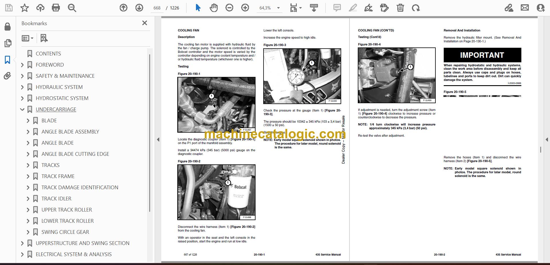
- COOLING FAN
- Description
- Testing
- Removal And Installation
- Parts Identification
- Disassembly And Assembly
- REMOVING AIR FROM HYDRAULIC SYSTEM
- BOOM SWING LOCK VALVE
- Description
- Removal And Installation
- Parts Identification
- Disassembly
- Assembly
- HYDRAULIC X-CHANGE VALVE
- Removal And Installation
- Parts Identification
- Disassembly
- Assembly
- HYDROSTATIC SYSTEM
- HYDROSTATIC SYSTEM INFORMATION
- Troubleshooting Chart
- Relief / Replenishing Valve Function
- Relief / Replenishing Valve Location
- Relief / Replenishing Valve Removal And Installation
- Charge Pressure Relief Valve Location
- Charge Pressure Relief Valve Removal And Installation
- TRAVEL PILOT PRESSURE
- HYDROSTATIC PUMP
- Removal And Installation
- Parts Identification (Front) (S/N AACD11001 & Above And AA8A11001 & Above)
- Disassembly
- Inspection
- Assembly
- Hydrostatic Pump Start-Up
- Mechanical Neutral Adjustment
- FAN / CHARGE PUMP
- DRIVE BELT SHIELD
- DRIVE BELT
- Adjustment
- Removal And Installation
- UNDERCARRIAGE
- BLADE
- ANGLE BLADE ASSEMBLY
- ANGLE BLADE
- ANGLE BLADE CUTTING EDGE
- TRACKS
- Track Lug Height
- Rubber Track Clearance
- Steel Track Clearance
- Adjustment
- Rubber Track Removal And Installation
- Steel Track Removal And Installation
- TRACK FRAME
- Disassembly And Assembly
- Recoil Spring Cylinder Disassembly And Assembly (S/N AACB11378 & Below, AACD11163 & Below, AA8A11150 & Below and AA8911261 & Below Without Replaceable Shaft.)
- Recoil Spring Cylinder Parts Identification (S/N AACB11378 & Below, AACD11163 & Below, AA8A11150 & Below And AA8911261 & Below With Replaceable Shaft)
- Recoil Spring Cylinder Disassembly And Assembly (S/N AACB11378 & Below, AACD11163 & Below, AA8A11150 & Below and AA8911261 & Below With Replaceable Shaft.)
- Recoil Spring Cylinder Parts Identification (S/N AACB11379 & Above, AACD11164 & Above, AA8A11151 & Above And AA8911262 & Above)
- Recoil Spring Cylinder Disassembly And Assembly (S/N AACB11379 & Above, AACD11164 & Above, AA8A11151 & Above and AA8911262 & Above)
- TRACK DAMAGE IDENTIFICATION
- Cutting Of Steel Cords
- Abrasion Of Embedded Metals
- Separation Of Embedded Metals
- Separation Of Embedded Metals Due To Corrosion
- Cuts On The Lug Side Rubber
- Cracks On The Lug Side Rubber Due To Fatigue
- Lug Abrasion
- Cracks And Cuts On The Lug Side Rubber
- Abrasion Of The Track Roller Side
- Cuts On The Edges Of Track Roller Side
- TRACK IDLER
- Parts Identification
- Disassembly
- Assembly
- UPPER TRACK ROLLER
- Parts Identification
- Disassembly
- Assembly
- LOWER TRACK ROLLER
- Parts Identification
- Disassembly
- Assembly
- SWING CIRCLE GEAR
- Swing Bearing Removal
- Swing Bearing Installation
- UPPERSTRUCTURE AND SWING SECTION
- UPPERSTRUCTURE
- ROPS CANOPY
- CAB
- Removal And Installation
- Door Removal And Installation
- Front Window Removal And Installation
- Right Side Rear Sliding Window Removal And Installation
- Right Side Front Sliding Window Removal And Installation
- Right Side Front And Rear Sliding Window Weather Strip Removal And Installation
- Right Side Front And Rear Sliding Window Wiper Strip Removal And Installation
- Glass Removal
- Glass Installation
- SEAT AND SEAT MOUNT
- RIGHT CONSOLE
- Console Cover Removal And Installation
- Console Base Removal And Installation
- LEFT CONSOLE
- Lower Console Cover Removal And Installation
- Upper Console Cover Removal And Installation
- Compression Spring Removal And Installation
- Compression Spring Disassembly And Assembly
- Lock Lever Removal And Installation
- Console Removal And Installation
- Disassembly And Assembly
- Console Switch Removal And Installation
- Console Base Removal And Installation
- ENGINE SPEED CONTROL
- Removal And Installation
- Disassembly And Assembly
- Adjustment (Later Models)
- BLADE CONTROL
- Lever Removal And Installation
- Linkage Removal And Installation
- Linkage Disassembly And Assembly
- Control Cable Removal And Installation
- RIGHT PEDAL AND LINKAGE
- Pedal Removal And Installation
- Pedal Disassembly And Assembly
- Control Cable Removal And Installation
- TRAVEL CONTROLS
- Removal And Installation
- Disassembly And Assembly
- Adjustment
- CONTROL LINKAGE ASSEMBLY
- FLOOR MAT AND FLOOR PLATES
- FUEL TANK
- HORN
- SWING FRAME
- Boom Swing Bracket Removal And Installation
- Boom Swing Bracket Hose Installation
- Bushing Removal
- Bushing Installation
- BOOM
- ARM
- Removal And Installation
- Arm To Boom Bushing Removal And Installation
- Arm To Bucket And Bucket Link Bushing Removal And Installation
- BUCKET
- Bucket Teeth Removal And Installation
- Bucket Side Cutting Edge Removal And Installation
- CLAMP
- TAILGATE
- X-CHANGE (PIN ON)
- Removal And Installation
- Parts Identification
- Disassembly And Assembly
- RIGHT SIDE COVER
- X-CHANGE (HYDRAULIC)
- Removal And Installation
- Parts Identification
- Disassembly
- Assembly
- COUNTERWEIGHT
- QUICK COUPLER (KLAC™ SYSTEM)
- Troubleshooting
- Daily Inspection
- Removal And Installation
- Parts Identification
- Disassembly
- Assembly
- QUICK COUPLER (LEHNHOFF® SYSTEM)
- Troubleshooting
- Daily Inspection
- Removal (MS03 And MS08)
- Installation (MS03 And MS08)
- Parts Identification (MS03)
- Disassembly And Assembly (MS03)
- Parts Identification (MS08)
- Disassembly (MS08)
- Assembly (MS08)
- ELECTRICAL SYSTEM & ANALYSIS
- ELECTRICAL SCHEMATICS
- ELECTRICAL SYSTEM INFORMATION
- Troubleshooting Chart
- Description
- Fuse And Relay Location
- BATTERY
- Servicing
- Removal And Installation
- Using A Booster Battery (Jump Starting)
- ALTERNATOR
- Engine Accessory Drive Belt
- Removal And Installation
- Alternator Identification
- Charging System Check
- Alternator Voltage Test
- Low Voltage Test
- High Voltage Test
- Rectifier Continuity (Diode) Test
- Alternator Regulator Test
- Parts Identification
- Disassembly
- Stator Continuity Test
- Stator Ground Test
- Rotor Continuity Test
- Rotor Ground Test
- Assembly
- STARTER
- Removal And Installation
- Parts Identification
- Disassembly
- Inspection And Repair
- Assembly
- LIGHTS
- Removal And Installation
- Boom Light Removal and Installation
- Boom Light Bulb Replacement
- TWO-SPEED SWITCH
- FUEL LEVEL SENDER
- Removal And Installation
- Testing
- DIAGNOSTICS SERVICE CODE
- DELUXE INSTRUMENT PANEL SETUP
- Passwords
- Password Entry (For Starting and Operating the Machine)
- Changing The Owner or Operator Password
- Password Lockout Feature
- Job Clock
- RPM
- ENGINE SYSTEM
- TROUBLESHOOTING
- MUFFLER
- AIR CLEANER
- RADIATOR
- ENGINE COMPONENTS AND TESTING
- Engine Compression Checking
- Glow Plug Removal And Installation
- Checking The Glow Plug
- Fuel Shut-off Solenoid Removal And Installation
- Fuel Injection Pump Check
- Fuel Injection Pump Removal And Installation
- Fuel Injection Pump Timing
- Fuel Injector Nozzles Removal And Installation
- Fuel Injector Nozzle Check
- Valve Clearance Adjustment
- ENGINE
- ENGINE FLYWHEEL
- Removal And Installation
- Hydraulic Pump Coupler
- Flywheel Ring Gear
- ENGINE FLYWHEEL (LATER MODELS)
- Removal And Installation
- Hydraulic Pump Coupler
- Flywheel Ring Gear
- RECONDITIONING THE ENGINE
- Cylinder Head Removal And Installation
- Cylinder Head Disassembly And Assembly
- Cylinder Head Servicing
- Cylinder Head Top Clearance
- Valve Guide Checking
- Reconditioning The Valve And Valve Seat
- Valve Spring
- Rocker Arm And Shaft Checking
- Timing Gearcase Cover Removal And Installation
- Idler Gear And Camshaft Removal And Installation
- Camshaft Servicing
- Idler Gear And Shaft Servicing
- Timing Gears Checking Backlash
- Fuel Camshaft Removal And Installation
- Fuel Camshaft Governor
- Crankshaft Gear Removal And Installation
- Oil Pump Removal And Installation
- Oil Pump Service
- Checking Engine Oil Pressure
- Relief Valve
- Piston And Connecting Rod Removal And Installation
- Piston And Connecting Rod Servicing
- Connecting Rod Alignment
- Crankshaft And Bearings Removal And Installation
- Crankshaft And Bearings Servicing
- Cylinder Bore Checking
- Water Pump Removal And Installation
- Water Pump Disassembly And Assembly
- HEATING, VENTILATION, AIR CONDITIONING
- HEATER COIL
- Removal And Installation With A/C
- Removal And Installation Without A/C
- BLOWER FAN
- Removal And Installation
- Disassembly And Assembly
- Resistor Removal And Installation
- HEATER VALVE
- AIR CONDITIONING SYSTEM FLOW
- COMPONENTS
- SAFETY
- REGULAR MAINTENANCE
- Heater Air Filter
- Engine Accessory Drive Belt
- Cleaning The Condenser
- BASIC TROUBLESHOOTING
- Poor A/C Performance
- Cleaning The A/C Evaporator Coil And Heater Coil
- Engine Accessory Drive Belt
- Checking The Electrical System
- Engine Coolant Bypassing The Heater Valve
- GENERAL AIR CONDITIONING SERVICE GUIDELINES
- Compressor Oil
- Compressor Oil Check
- Component Replacement And Refrigeration Leaks
- SYSTEM TROUBLESHOOTING CHART
- Blower Motor Does Not Operate
- Gauge Pressure Related Troubleshooting
- TEMPERATURE / PRESSURE
- AIR CONDITIONING SERVICE
- SYSTEM CHARGING AND RECLAMATION
- Reclamation Procedure
- Charging Procedure With A Manifold Gauge Set
- COMPRESSOR
- Removal And Installation
- Compressor Clutch Disassembly And Assembly
- CONDENSER
- RECEIVER / DRIER
- PRESSURE RELIEF VALVE
- PRESSURE SWITCH
- EVAPORATOR / HEATER UNIT
- Removal And Installation
- Disassembly And Assembly
- THERMOSTAT
- EXPANSION VALVE
- EVAPORATOR
- SPECIFICATIONS
- SPECIFICATIONS
- Excavator Machine Dimensions
- Performance (S/N AACD11001 & Above), (AA8A11001 & Above)
- Performance (S/N AACB11001 & Above), (AA8911001 & Above)
- Controls
- Engine
- Hydraulic System
- Hydraulic Cylinders
- Hydraulic Cycle Times
- Drive System
- Slew System
- Undercarriage
- Capacities
- Track
- Electrical
- ENGINE SPECIFICATIONS
- Fuel Injection Nozzles
- Fuel Injection Pump
- Cylinder Head
- Valves
- Valve Springs
- Valve Timing
- Rocker Arms
- Camshaft
- Tappet
- Cylinders
- Piston Rings
- Pistons
- Connecting Rods
- Oil Pump
- Crankshaft
- Timing Gear
- Thermostat
- Engine Bolt Torque
- Crankshaft Re-Grind Data
- TORQUE SPECIFICATIONS
- Torque for General SAE Bolts
- Torque For General Metric Bolts
- HYDRAULIC CONNECTION SPECIFICATIONS
- O-ring Face Seal Connection
- Straight Thread O-ring Fitting
- Tubelines And Hoses
- Flare Fitting
- O-ring Flare Fitting
- Port Seal Fitting
- HYDRAULIC FLUID SPECIFICATIONS
- FUEL, COOLANT AND LUBRICANTS
- CONVERSIONS
- Decimal And Millimeter Equivalents
- U.S. To Metric Conversion Chart
- ALPHABETICAL INDEX
- SERVICE MANUAL REVISIONS
- Revision No: 435-1
- Revision No: 435-2
- Revision No: 435-3
- Revision No: 435-4
- Revision No: 435-5
- Revision No: 435 – 6
Bobcat Software
Bobcat PDF Manuals


