The Bobcat 442 is a mid-size compact excavator that spends its life trenching, loading trucks, setting tanks, and doing farm ditch and culvert work. When something quits swinging, digging, or tracking straight, this is the kind of manual I pull out in the shop. Folks reach for it when a hose swap or filter change won't fix it and they actually need to open up a pump, chase a wiring fault, or set a hydraulic pressure the right way.
What this manual helps you do
- Diagnose hydraulic problems in the boom, arm, bucket, and travel circuits, then check pressures with a gauge the way Bobcat lays it out.
- Trace electrical issues using wiring diagrams so you can sort dead controls, no-start problems, and random blown fuses.
- Follow step-by-step teardown and reassembly for components like drive motors, swing gearboxes, cylinders, and major engine bolt-ons.
- Adjust and verify things like travel straightness, control responses, and safety interlocks after you replace parts.
- Replace heavy components, pins, and bushings with the right sequences and torque references so they stay together under hard digging.
Who this is for
This manual is for anyone running or fixing a Bobcat 442 excavator in the serial range 522311001 to 522399999, whether you're a small contractor, farm owner, or shop mechanic. If you only want to know what the buttons do or basic maintenance intervals, you want the operator's handbook instead.
FAQ
Q: Is this a searchable PDF, and can I read the wiring diagrams clearly?
A: Yes, it's a PDF you can search by keyword, and the wiring diagrams are meant to be zoomed in on a screen or printed.
Q: How do I know if it covers my exact 442?
A: Check your serial plate. If your 442 excavator serial number falls between 522311001 and 522399999, this is the right book.
Q: Is this the right document if I'm rebuilding or diagnosing, not just changing oil?
A: Yes, this is the workshop-level service manual, meant for real repair work and diagnostics.
Bottom line: If your Bobcat 442's serial number is in that range and you're doing your own repairs, this is the manual you want. If your serial is outside that range, skip it.
📘 Show Index
Table of Contents:
- MAINTENANCE SAFETY
- ALPHABETICAL INDEX
- CONTENTS
- FOREWORD
- SAFETY INSTRUCTIONS
- FIRE PREVENTION
- Maintenance
- Operation
- Electrical
- Hydraulic System
- Fueling
- Starting
- Spark Arrestor Exhaust System
- Welding And Grinding
- Fire Extinguishers
- SERIAL NUMBER LOCATIONS
- Excavator Serial Number
- Engine Serial Number
- DELIVERY REPORT
- BOBCAT EXCAVATOR IDENTIFICATION
- SAFETY & MAINTENANCE
- LIFTING AND BLOCKING THE EXCAVATOR
- LIFTING THE EXCAVATOR
- OPERATOR CAB
- Description
- Entering And Exiting The Excavator
- Raising And Lowering The Left Console
- Emergency Exit
- TRANSPORTING THE EXCAVATOR
- REAR COVER
- Opening And Closing The Rear Cover
- RIGHT SIDE COVER
- Opening And Closing The Right Side Cover
- SERVICE SCHEDULE
- AIR CLEANER
- Daily Check
- Replacing The Filters
- FRESH AIR FILTER (S/N 522311001 & ABOVE)
- FRESH AIR FILTER (S/N 528911001 & ABOVE AND S/N 528611001 & ABOVE)
- COOLING SYSTEM
- Cleaning The Cooling System
- Checking Coolant Level (S/N 522311001 & Above)
- Replacing The Coolant (S/N 522311001 & Above)
- FUEL SYSTEM
- Fuel Specifications
- Filling The Fuel Tank
- Removing Water From The Pre-Filter (S/N 522311001 & Above)
- Pre-Filter Removal (S/N 522311001 & Above)
- Pre-Filter Installation (S/N 522311001 & Above)
- Pre-Filter Removal And Installation (S/N 528911001 & Above And S/N 528611001 & Above)
- Fuel Filter Removal And Installation
- Draining The Fuel Tank
- ENGINE LUBRICATION SYSTEM
- Checking Engine Oil
- Replacing Oil And Filter
- HYDRAULIC SYSTEM
- Checking And Adding Hydraulic Oil
- Replacing The Hydraulic Oil
- Hydraulic Filter Removal (S/N 522311001 & Above)
- Hydraulic Filter Installation (S/N 522311001 & Above)
- Hydraulic Filter Removal (S/N 528911001 & Above And S/N 528611001 & Above)
- Hydraulic Filter Installation (S/N 528911001 & Above And S/N 528611001 & Above)
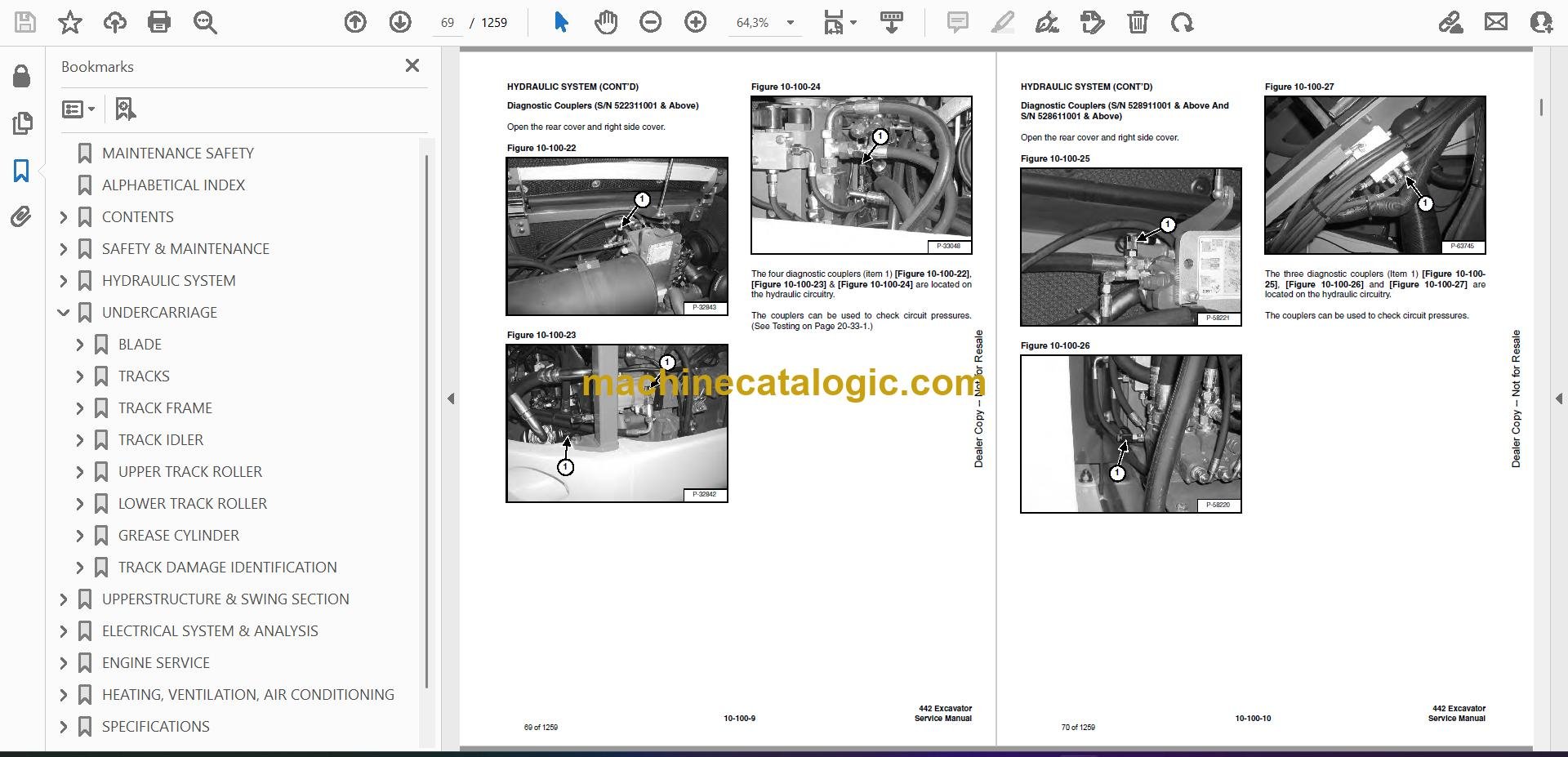
- Diagnostic Couplers (S/N 522311001 & Above)
- Diagnostic Couplers (S/N 528911001 & Above And S/N 528611001 & Above)
- LUBRICATION OF THE EXCAVATOR
- TRAVEL MOTOR
- Checking Oil Level
- Draining The Travel Motor
- ALTERNATOR BELT
- FAN/FUEL PUMP BELT
- Adjusting Belt Tension (S/N 522311001 & Above)
- AIR CONDITIONING COMPRESSOR BELT (S/N 522311001 & ABOVE)
- AIR CONDITIONING COMPRESSOR BELT (S/N 528911001 & ABOVE AND S/N 528611001 & ABOVE)
- CAB TILT PROCEDURE
- Installing The Cab Tilt Hinges
- Tilting The Cab
- HYDRAULIC SYSTEM
- HYDRAULIC / HYDROSTATIC SCHEMATICS
- HYDRAULIC SYSTEM INFORMATION
- Troubleshooting Chart
- Description
- BOOM CYLINDER
- Testing
- Removal And Installation
- Parts Identification
- Disassembly
- Assembly
- ARM CYLINDER
- Testing
- Removal And Installation
- Parts Identification
- Disassembly
- Assembly
- BOOM OFFSET CYLINDER
- Testing
- Removal And Installation
- Parts Identification
- Disassembly
- Assembly
- BUCKET CYLINDER
- Testing
- Removal And Installation
- Parts Identification
- Disassembly
- Assembly
- BLADE CYLINDER
- Testing
- Removal And Installation
- Parts Identification
- Disassembly
- Assembly
- RELIEF VALVES
- Description
- Testing The Three Spool Control Valve Main Relief Valve
- Adjusting The Three Spool Control Valve Main Relief Valve
- PORT RELIEF VALVES
- PRESSURE REDUCING VALVE (S/N 528911001 & ABOVE AND 528611001 & ABOVE)
- Description
- Testing
- Adjustment
- PRESSURE REDUCING VALVE (S/N 522311001 & ABOVE)
- Description
- Testing
- Adjustment
- DUMP VALVE
- Description
- Testing
- Adjustment
- Removal And Installation
- Parts Identification
- Disassembly And Assembly
- SIX SPOOL HYDRAULIC CONTROL VALVE
- Removal And Installation
- Control Valve Identification
- Disassembly And Assembly
- Left Travel And Right Travel Valve Section Disassembly And Assembly
- Boom, Arm, Bucket And Auxiliary Valve Section Disassembly And Assembly
- Inlet Valve Section Disassembly And Assembly
- THREE SPOOL HYDRAULIC CONTROL VALVE
- Removal And Installation
- Parts Identification
- Disassembly And Assembly
- Boom Offset And Blade Valve Section Disassembly And Assembly
- Inlet/Upperstructure Swing Valve Section Disassembly And Assembly
- HYDRAULIC PISTON PUMP (S/N 522311001 & ABOVE)
- Hydraulic Pump Work Sheet
- Testing Information
- Pump Testing
- Load Sense Relief Valve Adjustment
- Removal And Installation
- Coupler Removal And Installation
- Torque Limiter Valve Parts Identification
- Torque Limiter Valve Removal and Installation
- Torque Limiter Valve Disassembly
- Torque Limiter Valve Assembly
- Initial Torque Limiter Valve Setting
- Pump Control Parts Identification
- Pump Control Removal And Installation
- Pump Control Disassembly And Assembly
- Parts Identification
- Disassembly
- Assembly
- HYDRAULIC GEAR PUMP (S/N 522311001 & ABOVE)
- Removal And Installation
- Parts Identification
- Disassembly
- Assembly
- HYDRAULIC PISTON PUMP (S/N 528911001 & ABOVE AND S/N 528611001 & ABOVE)
- Hydraulic Pump Work Sheet
- Testing Information
- Pump Testing
- Load Sense Relief Valve Adjustment
- Removal And Installation
- Coupler Removal And Installation
- Torque Limiter Valve Parts Identification
- Torque Limiter Valve Removal and Installation
- Torque Limiter Valve Disassembly
- Torque Limiter Valve Assembly
- Initial Torque Limiter Valve Setting
- Pump Control Parts Identification
- Pump Control Removal And Installation
- Pump Control Disassembly And Assembly
- Parts Identification
- Disassembly
- Assembly
- HYDRAULIC GEAR PUMP (S/N 528911001 & ABOVE AND S/N 528611001 & ABOVE)
- Removal And Installation
- Parts Identification
- Disassembly
- Assembly
- ACCUMULATOR (S/N 522311001 & ABOVE)
- Description
- Removal And Installation
- ACCUMULATOR (S/N 528911001 & ABOVE AND S/N 528611001 & ABOVE)
- Description
- Removal And Installation
- TRAVEL MOTOR
- Removal And Installation
- Parts Identification
- Disassembly
- Assembly
- SWIVEL JOINT
- Removal And Installation
- Parts Identification
- Disassembly And Assembly
- SWING MOTOR
- Removal And Installation
- Parts Identification
- Disassembly
- Assembly
- SWING MOTOR DRIVE CARRIER
- Removal And Installation
- Parts Identification
- Disassembly
- Assembly
- SWING BRAKE VALVE
- Removal And Installation
- Parts Identification
- Disassembly And Assembly
- SWING BRAKE RELEASE VALVE
- SWING BRAKE RELEASE VALVE (CONT’D)
- Parts Identification
- Disassembly And Assembly
- JOYSTICK CONTROL PATTERN SELECTOR VALVE
- Removal And Installation
- Parts Identification
- Disassembly And Assembly
- JOYSTICK LOCKOUT/TWO SPEED VALVE (S/N 522311001 & ABOVE)
- Removal And Installation
- Parts Identification
- Disassembly And Assembly
- JOYSTICK LOCKOUT/TWO SPEED VALVE (S/N 528911001 & ABOVE AND S/N 528611001 & ABOVE)
- Removal And Installation
- Parts Identification
- Disassembly And Assembly
- RIGHT CONTROL LEVER (JOYSTICK)
- Testing
- Handle Removal And Installation
- Removal And Installation
- Parts Identification
- Disassembly And Assembly
- LEFT CONTROL LEVER (JOYSTICK)
- Testing
- Handle Removal And Installation
- Removal And Installation
- Parts Identification
- Disassembly and Assembly
- TRAVEL LEVER/FOOT PEDAL VALVE
- Left Travel Lever/Foot Pedal Valve Removal And Installation
- Right Travel Lever/Foot Pedal Valve Removal And Installation
- Parts Identification
- Disassembly And Assembly
- HYDRAULIC FILTER MOUNT
- HYDRAULIC RESERVOIR
- OIL COOLER
- SECONDARY FRONT AUXILIARY VALVE
- Removal And Installation
- Parts Identification
- Disassembly And Assembly
- HYDRAULIC BREAKER APPLICATION VALVE (S/N 522311001 & ABOVE)
- Removal And Installation
- Parts Identification
- Disassembly And Assembly
- AUXILIARY HYDRAULIC FLOW CONTROL VALVE (S/ N 522311001 & ABOVE)
- Removal And Installation
- Parts Identification
- Disassembly And Assembly
- AUXILIARY HYDRAULIC FLOW CONTROL/ HYDRAULIC BREAKER APPLICATION VALVE (S/N 528911001 & ABOVE AND S/N 528611001 & ABOVE)
- Removal And Installation
- Parts Identification
- Disassembly And Assembly
- BLADE VALVE
- Removal And Installation
- Parts Identification
- Disassembly And Assembly
- BLADE FLOAT VALVE
- Removal And Installation
- Parts Identification
- Disassembly And Assembly
- BOOM OFFSET VALVE
- Removal And Installation
- Parts Identification
- Disassembly And Assembly
- BOOM LOAD HOLDING VALVE
- Removal And Installation
- Parts Identification
- Disassembly
- Assembly
- OIL TEMPERATURE REGULATOR
- Description
- Removal And Installation
- AUXILIARY HYDRAULICS SELECTOR VALVE
- HYDRAULIC PISTON PUMP DRIVE COUPLER
- UNDERCARRIAGE
- BLADE
- TRACKS
- Track Lug Height
- Rubber Track Clearance
- Steel Track Clearance
- Track Adjustment
- Rubber Track Removal And Installation
- TRACK FRAME
- Disassembly And Assembly
- Drive Sprocket Removal And Installation
- TRACK IDLER
- Parts Identification
- Disassembly
- Assembly
- UPPER TRACK ROLLER
- Parts Identification
- Disassembly
- Assembly
- LOWER TRACK ROLLER
- Parts Identification
- Disassembly
- Assembly
- GREASE CYLINDER
- Parts Identification
- Disassembly
- Assembly
- TRACK DAMAGE IDENTIFICATION
- Cutting Of Steel Cords
- Abrasion Of Embedded Metals
- Separation Of Embedded Metals
- Separation Of Embedded Metals Due To Corrosion
- Cuts On The Lug Side Rubber
- Cracks On The Lug Side Rubber Due To Fatigue
- Lug Abrasion
- Cracks And Cuts On The Lug Side Rubber
- Abrasion Of The Track Roller Side
- Cuts On The Edges Of Track Roller Side
- UPPERSTRUCTURE & SWING SECTION
- UPPERSTRUCTURE
- Removal And Installation
- Swing Bearing Removal And Installation
- CAB
- Removal And Installation
- Door Removal And Installation
- Front Window Removal And Installation
- Front Window Disassembly And Assembly (S/N 522311001 & Above)
- Front Window Gas Strut Removal And Installation
- Front Window Pivot Frame Removal And Installation
- Lower Front Widow Removal And Installation
- Door, Left Side, Right Side And Rear Window Removal
- Door, Left Side, Right Side And Rear Window Installation
- Cab Visor Removal And Installation
- Top Window Removal And Installation
- SEAT AND SEAT MOUNT
- RIGHT CONSOLE
- LEFT CONSOLE
- Removal And Installation
- Disassembly And Assembly
- Console Lockout Switch Removal And Installation
- ENGINE SPEED CONTROL
- Removal And Installation
- Disassembly And Assembly
- CONTROL LEVERS
- FUEL TANK
- HORN
- SWING FRAME
- Removal And Installation
- Bushing Removal And Installation
- FLOOR MAT
- BOOM
- Removal And Installation
- Bushing Removal And Installation
- ARM
- Removal And Installation
- Bushing Removal And Installation
- BUCKET
- REAR COVER
- RIGHT SIDE COVER
- COUNTERWEIGHT
- ELECTRICAL SYSTEM & ANALYSIS
- ELECTRICAL SCHEMATICS
- ELECTRICAL SYSTEM INFORMATION
- Troubleshooting Chart
- Description
- Fuse And Relay Location (S/N 522311001 & Above)
- Fuse And Relay Location (S/N 528911001 & Above And S/N 528611001 & Above)
- BATTERY
- Servicing
- Removal And Installation
- Using A Booster Battery (Jump Starting)
- ALTERNATOR
- Removal And Installation (S/N 522311001 & Above)
- Removal And Installation (S/N 528911001 & Above And 528611001 & Above)
- Parts Identification
- Alternator Identification
- Charging System Check
- Rectifier Continuity (Diode) Test
- Disassembly
- Stator Continuity Test
- Stator Ground Test
- Rotor Continuity Test
- Rotor Ground Test
- Capacitor Continuity Test
- Assembly
- STARTER
- Removal And Installation (S/N 522311001 & Above)
- Removal And Installation (S/N 528911001 & Above And S/N 528611001 & Above)
- Parts Identification (All Models)
- Disassembly (All Models)
- Inspection And Repair (All Models)
- Assembly (All Models)
- STARTER (S/N 528911001 & ABOVE & S/N 528611001 & ABOVE)
- FRONT CAB LIGHT
- Removal And Installation
- Disassembly And Assembly
- TWO SPEED SWITCH
- FUEL LEVEL SENDER
- WIPER MOTOR
- BATTERY DISCONNECT SWITCH
- INSTRUMENT PANEL
- Removal And Installation
- E-Prom Information
- ENGINE SERVICE
- TROUBLESHOOTING
- MUFFLER (S/N 522311001 & ABOVE)
- MUFFLER (S/N 528911001 & ABOVE AND S/N 528611001 & ABOVE)
- AIR CLEANER
- RADIATOR/OIL COOLER (S/N 522311001 & ABOVE)
- RADIATOR/OIL COOLER (S/N 528911001 & ABOVE AND S/N 528611001 & ABOVE)
- Removal And Installation
- Hydraulic Check Valve Removal And Installation
- Hydraulic Check Valve Disassembly And Assembly
- ENGINE COMPONENTS AND TESTING (S/N 522311001 & ABOVE)
- Engine Compression Checking
- Checking the Glow Plugs
- Glow Plug Removal And Installation
- Fuel Shutoff Solenoid Checking
- Fuel Shutoff Solenoid Removal And Installation
- Fuel Injection Pump Removal
- Fuel Injection Pump Timing
- Fuel Injection Pump Installation
- Fuel Injector, Checking
- Fuel Injector Disassembly
- Fuel Injector Assembly
- Valve Clearance Adjustment
- Thermostat
- ENGINE COMPONENTS AND TESTING (S/N 528911001 & ABOVE AND S/N 528611001 & ABOVE)
- Engine Compression Checking
- Checking the Manifold Heater
- Manifold Heater Removal And Installation
- Fuel Shutoff Solenoid Checking
- Fuel Shutoff Solenoid Removal And Installation
- Fuel Injection Pump Removal
- Fuel Injection Pump Timing
- Fuel Injection Pump Installation
- Fuel Injector Removal And Installation
- Fuel Injector Removal And Installation (Cont’d)
- Fuel Injector, Checking
- Fuel Injector Disassembly
- Fuel Injector Assembly
- Timing Belt Inspection
- Timing Belt Removal
- Timing Belt Installation
- Valve Clearance Adjustment
- Valve Timing, Checking
- Thermostat, Oil Pressure Control Valves & Heater Connections
- Aneroid Device
- ENGINE (S/N 522311001 & ABOVE)
- ENGINE (S/N 528911001 & ABOVE AND S/N 528611001 & ABOVE)
- FLYWHEEL (S/N 522311001 & ABOVE)
- Removal And Installation
- Flywheel Ring Gear
- FLYWHEEL (S/N 528911001 & ABOVE AND S/N 528611001 & ABOVE)
- Removal And Installation
- Flywheel Ring Gear
- RECONDITIONING THE ENGINE (S/N 522311001 & ABOVE)
- Deutz Engine Tools Identification Chart
- Disassembly
- Assembly
- Cylinder, Checking
- Camshaft Bearing, Checking
- Camshaft Bearing, Removal And Installation
- Balancing Shaft Bearing, Checking (If Equipped)
- Balancing Shaft Bearing, Removal And Installation
- Control Rod Guide Bushing Installation
- Rear Cover Seal Removal And Installation
- Rear Cover Seal Removal And Installation (Cont’d)
- Crankshaft, Checking
- Connecting Rod, Checking
- Piston, Checking
- Piston Pin, Checking
- Piston Rings Installation
- Piston Installation On The Connecting Rod
- Cylinder Head Disassembly
- Valves, Checking
- Valve Clearance Adjustment
- Cylinder Head Assembly
- Rocker Arm And Bracket, Checking
- Front Cover Disassembly
- Front Cover Assembly
- Turbo Charger Removal and Installation
- RECONDITIONING THE ENGINE (S/N 528911001 & ABOVE AND S/N 528611001 & ABOVE)
- Deutz Engine Tools Identification Chart
- Disassembly
- Assembly
- Cylinder, Checking
- Camshaft Bearing, Checking
- Camshaft Bearing, Removal And Installation
- Control Rod Guide Bushing Removal
- Control Rod Guide Bushing Installation
- Rear Cover Seal Removal And Installation
- Crankshaft, Checking
- Connecting Rod, Checking
- Piston, Checking
- Piston Pin, Checking
- Piston Rings Installation
- Piston Installation On The Connecting Rod
- Cylinder Head Disassembly
- Valves, Checking
- Valve Clearance Adjustment
- Cylinder Head Assembly
- Rocker Arm And Bracket, Checking
- Front Cover Disassembly
- Front Cover Assembly
- Turbo Charger Removal and Installation
- Crankshaft Gear Mounting Bolt Torque Procedure
- HEATING, VENTILATION, AIR CONDITIONING
- EVAPORATOR/HEATER UNIT (S/N 522311001 & ABOVE)
- EVAPORATOR/HEATER UNIT (S/N 528911001 & ABOVE AND 528611001 & ABOVE)
- Removal And Installation
- Disassembly And Assembly
- HEATER/AC FAN
- Removal And Installation
- Resistor Removal And Installation
- HEATER VALVE
- AIR CONDITIONING SYSTEM FLOW
- COMPONENTS (S/N 522311001 & ABOVE)
- COMPONENTS (S/N 528911001 & ABOVE AND 52864001 & ABOVE)
- SAFETY
- REGULAR MAINTENANCE
- Heater Air Filter
- Air Conditioning Compressor Belt
- Cleaning The Condenser
- BASIC TROUBLESHOOTING
- Poor A/C Performance
- Compressor Drive Belt Inspection
- Cleaning The A/C Evaporator Coil & Heater Coil (S/N 522311001 & Above)
- Cleaning The A/C Evaporator Coil And Heater Coil (S/N 528911001 & Above And 528611001 & Above)
- Checking The Electrical System
- Engine Coolant Bypassing The Heater Valve
- GENERAL AIR CONDITIONING SERVICE GUIDELINES
- Compressor Oil
- Compressor Oil Check
- Component Replacement And Refrigeration Leaks
- SYSTEM TROUBLESHOOTING CHART
- Blower Motor Does Not Operate
- Gauge Pressure Related Troubleshooting
- TEMPERATURE/PRESSURE
- AIR CONDITIONING SERVICE
- SYSTEM CHARGING AND RECLAMATION
- COMPRESSOR (S/N 522311001 & ABOVE)
- COMPRESSOR (S/N 528911001 & ABOVE AND S/N 528611001 & ABOVE)
- Removal And Installation
- Parts Identification
- Compressor Clutch Disassembly And Assembly
- CONDENSER (S/N 522311001 & ABOVE)
- CONDENSOR (S/N 528911001 & ABOVE AND S/N 528611001 & ABOVE)
- RECEIVER/DRYER (S/N 522311001 & ABOVE)
- RECEIVER/DRYER (S/N 528911001 & ABOVE AND 528611001 & ABOVE))
- PRESSURE SWITCH (S/N 522311001 & ABOVE)
- PRESSURE SWITCH (S/N 528911001 & ABOVE AND 528611001 & ABOVE)
- HEATER COIL/EVAPORATOR
- THERMOSTAT
- EXPANSION VALVE
- UPGRADED AIR CONDITIONING SYSTEM
- Evaporator Unit Removal And Installation
- Disassembly And Assembly
- Thermostat Removal And Installation
- Evaporator Removal And Installation
- Fan Removal And Installation
- Switch Removal And Installation
- SPECIFICATIONS
- HYDRAULIC EXCAVATOR SPECIFICATIONS
- Machine Dimensions
- Performance
- Controls
- Engine (S/N 522311001 & Above)
- Engine (S/N 528911001 & Above And S/N 528611001 & Above)
- Electrical
- Hydraulic System (S/N 522311001 & Above)
- Hydraulic System (S/N 528911001 & Above And S/N 528611001 & Above)
- Hydraulic Cycle Times
- Swing System
- Hydraulic Cylinders
- Drive System
- Brakes
- Undercarriage
- Track
- Capacities (S/N 522311001 & Above)
- Capacities (S/N 528911001 & Above And S/N 528611001 & Above)
- Digging Force
- ENGINE SPECIFICATIONS (S/N 522311001 & ABOVE)
- General
- Fuel System
- Valve, Valve Guide and Seat Insert
- Piston And Rings
- Connecting Rod
- Cylinder Head and Block
- Crankshaft And Main Bearings
- Camshaft And Bearings
- Oil Pump
- Governor
- Engine Balancing Shaft And Bearings
- ENGINE SPECIFICATIONS (S/N 528911001 & ABOVE AND S/N 528611001 & ABOVE)
- General
- Fuel System
- Valve, Valve Guide and Seat Insert
- Piston And Rings
- Connecting Rod
- Cylinder Head and Block
- Crankshaft And Main Bearings
- Camshaft And Bearings
- Oil Pump
- ENGINE BOLT TORQUE (S/N 522311001 & ABOVE)
- ENGINE BOLT TORQUE (S/N 528911001 & ABOVE AND S/N 528611001 & ABOVE)
- EXCAVATOR BOLT TORQUE
- TORQUE SPECIFICATIONS FOR BOLTS
- Torque For General SAE Bolts
- Torque For General Metric Bolts
- HYDRAULIC FLUID SPECIFICATIONS
- FUEL, COOLANT AND LUBRICANTS
- Chart (S/N 522311001 & Above)
- Chart (S/N 528911001 & Above And S/N 528611001 & Above)
- CONVERSIONS
- Decimal And Millimeter Equivalents
- U.S. To Metric Conversion
- SERVICE MANUAL REVISIONS
- SMR-1
- SMR-2
- SMR-3
- SMR-4
- SMR-5
- SMR-6
- SMR-7
- SMR-8
Bobcat Software
Bobcat PDF Manuals


