On an MT50 mini track loader, the manual comes out when the machine stops pulling on one side, the lift quits, or it just cranks and won't start in a tight corner of a yard. The folks who reach for this are usually the owner-operator, a small contractor's in-house mechanic, or a field tech like me who needs the right procedure before tearing in. They're trying to fix hydraulic or drive issues, chase electrical faults, or do engine work without guessing and causing a parts run delay.
What this manual helps you do
- Diagnose no-move or weak-drive complaints in the hydrostatic system, and check pressures with a gauge set from your truck.
- Trace electrical faults using wiring diagrams so you're not blindly swapping relays and switches.
- Follow step-by-step teardown and reassembly on the undercarriage, drive motors, and related components in tight working space.
- Rebuild or replace hydraulic cylinders, control valves, and related plumbing with the right sequences and torque references.
- Set and verify adjustments on linkages, controls, and safety interlocks after repairs so the machine works safely.
Who this is for
This is a workshop service manual for the Bobcat MT50 Loader Mini Track, serial numbers 520611001 to 520699999. It fits small contractors, rental fleets, shop mechanics, and owner-operators doing their own repairs. If you just want operating tips or daily maintenance, you want the operator's handbook instead, not this manual.
FAQ
Q: Is it a searchable PDF, and can I read the wiring diagrams?
A: These MT50 service manuals are normally supplied as searchable PDFs, and the wiring diagrams are laid out to be readable on-screen or printed.
Q: Will it cover my exact MT50 machine?
A: Yes, if your serial number falls between 520611001 and 520699999, this is the right manual. If it's outside that range, you need a different one.
Q: Is this the right document if I'm doing my own repairs?
A: Yes. This is the workshop-level service manual, meant for real repair work, not just basic operation or parts lookup.
Bottom line: If your MT50's serial number is in that range and you're actually wrenching on it, this is the manual you want. If you only need how-to-drive info, skip it.
📘 Show Index
Table of Contents:
- MAINTENANCE SAFETY
- ALPHABETICAL INDEX
- CONTENTS
- FOREWORD
- SAFETY INSTRUCTIONS
- SERIAL NUMBER LOCATIONS
- Loader Serial Number
- Engine Serial Number
- DELIVERY REPORT
- BOBCAT LOADER INDENTIFICATION
- SAFETY AND MAINTENANCE
- LIFTING AND BLOCKING THE LOADER
- Procedure
- Four Point Lift
- LIFT ARM SUPPORT DEVICE
- Installing Lift Arm Support Device
- Removing Lift Arm Support Device
- TRANSPORTING THE BOBCAT LOADER
- TOWING THE LOADER
- SERVICE SCHEDULE
- AIR CLEANER SERVICE
- Replacing the Filter Element
- ENGINE COOLING SYSTEM
- Checking The Coolant Level
- Cleaning The Cooling System
- Replacing The Coolant
- FUEL SYSTEM
- Fuel Specifications
- Filling The Fuel Tank
- Fuel Filter
- Removing Air From The Fuel System
- ENGINE LUBRICATION SYSTEM
- Checking Engine Oil
- Oil Chart
- Replacing Oil And Filter
- HYDRAULIC SYSTEM
- Checking And Adding Fluid
- Replacing Hydraulic Filter
- Hydraulic Breather Cap
- Replacing Hydraulic Fluid
- BOB-TACH
- Inspection and Maintenance
- LUBRICATION OF THE BOBCAT LOADER
- SPARK ARRESTOR MUFFLER
- HYDRAULIC SYSTEM
- HYDRAULIC SCHEMATICS
- HYDRAULIC SYSTEM INFORMATION
- Workgroup Troubleshooting Chart
- Hydraulic Function Troubleshooting
- Hydraulic Drive Troubleshooting Chart
- CYLINDER (LIFT)
- Checking The Lift Cylinder(s)
- Removal And Installation
- Parts Identification
- Disassembly And Assembly
- CYLINDER (TILT)
- Checking The Tilt Cylinder
- Removal And Installation
- Parts Identification
- Disassembly And Assembly
- MAIN RELIEF VALVE
- Checking (Workgroup Hydraulic Control Valve)
- Removal And Installation (Workgroup Hydraulic Control Valve)
- Checking (Left Drive)
- Adjustment (Left Drive)
- Removal And Installation (Left Drive)
- Checking (Right Drive)
- Adjustment (Right Drive)
- Removal And Installation (Right Drive)
- PORT RELIEF VALVE
- Checking The Port Relief Valves (Lift)
- Adjusting The Port Relief Valves (Lift)
- Removal And Installation (Lift)
- Checking The Port Relief Valves (Tilt)
- Adjusting The Port Relief Valves (Tilt)
- Removal And Installation (Tilt)
- HYDRAULIC CONTROL VALVE (DRIVE)
- Removal And Installation
- Disassembly
- Assembly
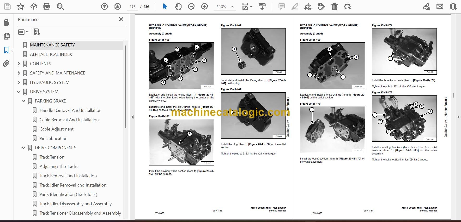
- HYDRAULIC CONTROL VALVE (WORK GROUP)
- Removal And Installation
- Disassembly
- Assembly
- HYDRAULIC PUMP (ALUMINMUM) (S/N 520611905 & Below)
- Check The Output Of The Hydraulic Pump
- Removal And Installation
- Coupler Removal And Installation
- Parts Identification
- Disassembly And Assembly
- Inspection
- HYDRAULIC PUMP (CAST IRON) (S/N 520611906 & above)
- Check The Output Of The Hydraulic Pump
- Removal And Installation
- Parts Identification
- Disassembly And Assembly
- HYDRAULIC FILTER
- Housing Removal And Installation
- HYDRAULIC FLUID RESERVOIR
- DRIVE MOTOR
- Removal And Installation
- Parts Identification
- Disassembly
- Inspection
- Assembly
- COUNTERBALANCE VALVE
- Removal And Installation
- Disassembly And Assembly
- SPEED CONTROL VALVE
- Removal And Installation (S/N 520612036 & Below)
- Removal And Installation (S/N 520612036 & Below) (Cont’d)
- SPEED CONTROL VALVE
- Removal And Installation (S/N 520612037 & Above)
- Removal And Installation (S/N 520612037 & Above) (Cont’d)
- Parts Identification
- Disassembly And Assembly
- SINGLE INLET MODE SELECT VALVE
- Removal And Installation (S/N 520612036 & Below)
- Parts Identification (S/N 520612036 & Below)
- Disassembly And Assembly (S/N 520612036 & Below)
- Removal And Installation (S/N 520612037 & Above)
- Parts Identification (S/N 520612037 & Above)
- Disassembly And Assembly (S/N 520612037 & Above)
- DUAL INLET MODE SELECT VALVE
- Removal And Installation (S/N 520612036 & Below)
- Parts Identification (S/N 520612036 & Below)
- Removal And Installation (S/N 520612037 & Above)
- Parts Identification (S/N 520612037 & Above)
- LIFT LOCK VALVE
- Solenoid Testing
- Solenoid Removal And Installation
- Removal And Installation
- Disassembly And Assembly
- TILT LOCK VALVE
- Solenoid Testing
- Solenoid Removal And Installation
- Removal And Installation
- Disassembly And Assembly
- REVERSE SPEED LIMIT VALVE
- Removal and Installation
- Disassembly and Assembly
- HYDRAULIC OIL COOLER
- DRIVE SYSTEM
- PARKING BRAKE
- Handle Removal And Installation
- Cable Removal And Installation
- Cable Adjustment
- Pin Lubrication
- DRIVE COMPONENTS
- Track Tension
- Adjusting The Tracks
- Track Removal and Installation
- Track Idler Removal and Installation
- Parts Identification (Track Idler)
- Track Idler Disassembly and Assembly
- Track Tensioner Disassembly and Assembly
- Track Roller Removal and Installation
- Parts Identification (Track Roller)
- Track Roller Disassembly and Assembly
- Track Frame Removal and Installation
- Track Damage Identification
- LEFT AND RIGHT TRAVEL ADJUSTMENT
- Description
- Adjustment (S/N 520611001 thru 520611064, 520611066, 520611068 thru 520611072, 520611074 thru 520611080, 520611082 thru 520611085, 520611087, 520611088, 520611090, 520611091, 520611093, 520611095, 520611096, 520611098, 520611100 thru 52061110…
- Adjustment (S/N 520611065, 520611067, 520611073, 520611081, 520611086, 520611089, 520611092, 520611094, 520611097, 520611099 thru 520611105, 520611107 thru 520611118, 520611120 thru 520611129)
- MAIN FRAME
- BOB-TACH
- Removal
- Installation
- Seal Removal And Installation
- Lever And Wedge Removal
- LIFT ARM
- REAR DOOR
- FUEL TANK
- CONTROL PANEL PLATE
- HAND BAR
- Removal and Installation
- Adjustment
- ENGINE COVER
- Removal and Installation
- Disassembly And Assembly
- COUNTERWEIGHT
- REVERSE STOP PANEL
- Description
- Inspecting Function
- Adjusting
- Removal And Installation
- ELECTRICAL SYSTEM & ANALYSIS
- ELECTRICAL SCHEMATICS
- ELECTRICAL SYSTEM INFORMATION
- Electrical Troubleshooting Chart
- BATTERY
- Removal and Installation
- Servicing
- Using A Booster Battery (Jump Starting)
- ALTERNATOR
- Removal and Installation (S/N 520611001-520611125)
- Removal and Installation (S/N 520611126 & Above)
- ALTERNATOR (CONT’D)
- Adjusting The Alternator Belt
- Description
- Tests
- Alternator Output Test
- Full Field Test
- Alternator Regulator Test
- Alternator Regulator Test Using Voltmeter
- STARTER
- Removal And Installation
- Checking The Starter In The Loader
- Parts Identification
- Disassembly
- Inspection And Repair
- No Load Test
- Assembly
- INSTRUMENT PANEL
- Removal And Installation
- Disassembly And Assembly
- BLOWER ASSEMBLY
- Removal And Installation
- Parts Identification
- Disassembly And Assembly
- ELECTRICAL ATTACHMENT CONTROL REFERENCE
- Attachment Control Identification Chart
- ENGINE SERVICE
- ENGINE INFORMATION AND TESTING
- Engine Troubleshooting Chart
- ENGINE SPEED CONTROL
- Removal And Installation
- Disassembly And Assembly
- Cable Removal and Installation
- MUFFLER
- AIR CLEANER
- Housing Removal and Installation
- RADIATOR
- ENGINE COMPONENTS AND TESTING
- Valve Clearance Adjustment
- Fuel Injection Pump Check
- Fuel Lift Pump Removal And Installation
- Fuel Injection Pump Removal And Installation
- Fuel Injection Pump Timing
- Fuel Injector Nozzles Checking
- Fuel Injector Nozzles Removal
- Fuel Injector Nozzles Installation
- Glow Plugs Checking
- Engine Compression Test Procedure
- ENGINE
- Removal And Installation
- Engine Mount Replacement
- FRONT ENGINE MOUNT
- SIDE ENGINE MOUNTS
- FLYWHEEL AND HOUSING
- Flywheel Removal And Installation
- Hydraulic Pump Coupler Removal And Installation (Early Version)
- Hydraulic Pump Coupler Removal And Installation (Later Version)
- Flywheel Ring Gear
- RECONDITIONING THE ENGINE
- Cylinder Head Removal And Installation
- Cylinder Head Inspection
- Cylinder Head Top Clearance
- Rocker Arm And Shaft Checking
- Valve Removal
- Valve Spring Checking
- Valve Guide Checking
- Reconditioning The Valve And Valve Seat
- Timing Gearcase Cover Removal And Installation
- Idler Gear And Camshaft Removal And Installation
- Servicing The Idler Gear And Shaft
- Checking Timing Gear Backlash
- Fuel Camshaft Removal And Installation
- Governor
- Crankshaft Gear Removal And Installation
- Oil Pump Removal And Installation
- Oil Pump Service
- Checking Engine Oil Pressure
- Relief Valve
- Piston And Connecting Rod Removal And Installation
- Piston And Connecting Rod Servicing
- Connecting Rod Alignment
- Crankshaft And Bearings Removal And Installation
- Inspection Of Crankshaft And Bearings
- Cylinder Bore Inspection
- Thermostat Removal And Installation
- Testing The Thermostat
- Water Pump Removal And Installation
- Water Pump Disassembly And Assembly
- SPECIFICATIONS
- LOADER SPECIFICATIONS (MT50)
- Loader Dimensions
- Performance
- Controls
- Engine
- Hydraulic System
- Electrical
- Drive System
- Capacities
- Tracks
- Ground Pressure
- ENGINE SPECIFICATIONS
- Engine
- Fuel Injector Nozzles
- Fuel Injection Pump
- Cylinder Head
- Valves
- Valve Springs
- Rocker Arms
- Camshaft
- Cylinders
- Piston Rings
- Pistons
- Crankshaft
- Oil Pump
- Thermostat
- Engine Bolt Torque
- Re-Grinding The Crankshaft
- LOADER TORQUE
- TORQUE SPECIFICATIONS FOR BOLTS
- Torque For General SAE Bolts
- Torque For General Metric Bolts
- Torque For Kubota Metric Engine Bolts
- HYDRAULIC CONNECTION SPECIFICATIONS
- O-ring Face Seal Connection
- Straight Thread O-ring Fitting
- Tubelines And Hoses
- Flare Fitting
- O-ring Flare Fitting
- Port Seal Fitting
- HYDRAULIC FLUID SPECIFICATIONS
- CONVERSIONS
- Decimal And Millimeter Equivalents
- SMR
- Revision No: MT50-1
- Revision No: MT50-2
- Revision No: MT50-3
Bobcat Software
Bobcat PDF Manuals


