$ 0
0
$ 0
0

Bobcat S16 Loader Service Manual (SN B47F11001-B47F99999)

Format: PDF (Printable Document)

File Language: English

File Pages: 476

File Size: 55.08 MB (Speed Download Link)

Brand: Bobcat

Model: S16 Loader

Book No: 7312959

Serial No: SN B47F11001-B47F99999

Type of Document: Service Manual

Categories: ,

$ 45

Share:

Bobcat S16 Loader Service Manual (SN B47F11001-B47F99999)

On a real job, an S16 skid-steer is hauling pallets, loading trucks, or cleaning lots where you barely have room to swing a wrench. The service manual is what I grab when I'm in a tight yard, laptop on the bucket, trying to sort a no-move condition or a dead auxiliary circuit without wasting a day and a parts run. This specific book is for the S16 loader in the serial range listed, and it's aimed at people who actually turn bolts and probe wires. You use it when you need step-by-step teardown, specs, and test procedures, not just how to drive the machine.

What this manual helps you do

  • Diagnose no-start or low-power issues on the small diesel engine and verify fuel and air system checks
  • Trace and troubleshoot electrical faults using wiring diagrams and step sequences instead of guessing at bad switches
  • Check and set hydraulic and hydrostatic pressures with gauges so you're not just swapping pumps and drive motors on a hunch
  • Follow teardown and reassembly procedures for cylinders, drive motors, and major loader components in a real shop setting
  • Adjust, verify, and replace controls, linkages, and Bob-Tach components so the loader arms and attachments work correctly

Who this is for

This is for small contractors, owner-operators, rental fleets, and field or shop techs who maintain an S16 in the B47F11001-B47F99999 serial range. If you only need basic operating instructions or daily checks, you want the operator's handbook instead, not this manual.

FAQ

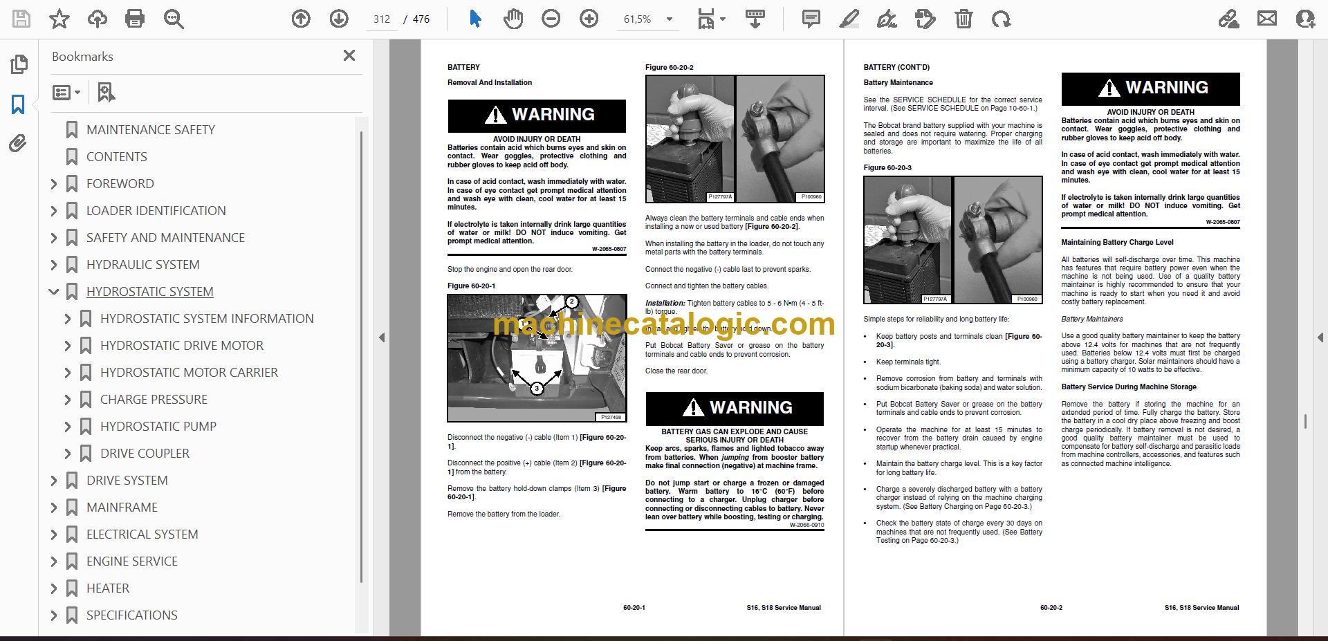
Q: Is this a searchable PDF, and can I read the wiring diagrams on a laptop or tablet?

A: Yes, service manuals like this are normally provided as searchable PDFs and the wiring diagrams are made to zoom in on-screen.

Q: How do I know it fits my exact S16?

A: If your serial number falls between B47F11001 and B47F99999, this is the correct service manual for your machine.

Q: I'm just doing routine fluid changes. Is this the right document?

A: You can use it, but for simple maintenance the operator's handbook is easier. This manual is aimed at real repair and diagnostic work.

Bottom line: If your S16 is in that serial range and you're actually repairing or diagnosing it, this is the manual you want. If you're just learning to run it, skip this one.

📘 Show Index

Table of Contents:

  • MAINTENANCE SAFETY
  • CONTENTS
  • FOREWORD
    • FOREWORD
    • SAFETY INSTRUCTIONS
      • Safe Operation Is The Operator’s Responsibility
      • Safe Operation Needs A Qualified Operator
      • Avoid Silica Dust
    • FIRE PREVENTION
      • Maintenance
      • Operation
      • Electrical
      • Hydraulic System
      • Fueling
      • Starting
      • Welding And Grinding
      • Fire Extinguishers
    • SERIAL NUMBER LOCATIONS
      • Loader Serial Number
      • Engine Serial Number
    • DELIVERY REPORT
  • LOADER IDENTIFICATION
    • S16 Radial Lift
    • S18 Vertical Lift
  • SAFETY AND MAINTENANCE
    • LIFTING AND BLOCKING THE LOADER
      • Procedure
    • LIFT ARM SUPPORT DEVICE (S16 RADIAL PATH)
      • Description
      • Installing
      • Removing
    • LIFT ARM SUPPORT DEVICE (S18 VERTICAL PATH)
      • Description
      • Installing
      • Removing
    • OPERATOR CAB
      • Description
      • Raising
      • Lowering
      • Special Applications Kit
      • Special Applications Kit Inspection And Maintenance
    • TRANSPORTING THE LOADER ON A TRAILER
      • Loading And Unloading
      • Fastening
    • TOWING THE LOADER
      • Procedure
    • SERVICE SCHEDULE
      • Maintenance Intervals
    • AIR CLEANER SERVICE
      • Replacing Filter Elements
    • ENGINE COOLING SYSTEM
      • Cleaning
      • Checking And Adding Coolant
      • Removing And Replacing Coolant
    • FUEL SYSTEM
      • Fuel Specifications
      • Biodiesel Blend Fuel
      • Filling The Fuel Tank
      • Fuel Filters
      • Removing Air From The Fuel System
    • ENGINE LUBRICATION SYSTEM
      • Checking And Adding Engine Oil
      • Engine Oil Chart
      • Removing And Replacing Oil And Filter
    • HYDRAULIC / HYDROSTATIC SYSTEM
      • Checking And Adding Fluid
      • Hydraulic / Hydrostatic Fluid Chart
      • Removing And Replacing Hydraulic Fluid
      • Removing And Replacing Hydraulic / Hydrostatic Filter
      • Removing And Replacing Hydraulic Case Drain Filter
      • Replacing Reservoir Breather Cap
    • FINAL DRIVE TRANSMISSION (CHAINCASE)
      • Checking And Adding Fluid
      • Removing And Replacing Fluid
    • AUXILIARY CONTROL LOCKBOLT
      • Procedure
    • ATTACHMENT COUPLER
      • Inspection And Maintenance
    • LUBRICATING THE LOADER
      • Lubrication Locations (S16 Radial Path)
      • Lubrication Locations (S18 Vertical Path)
    • TYRE MAINTENANCE
      • Wheel Nuts
      • Rotating
      • Mounting
    • PIVOT PINS
      • Inspection And Maintenance
    • SEAT BAR RESTRAINT SYSTEM
      • Description
      • Inspection And Maintenance
    • LOADER STORAGE AND RETURN TO SERVICE
      • Storage
      • Return To Service
    • STOPPING THE ENGINE AND LEAVING THE LOADER
      • Procedure
    • EMERGENCY EXIT
      • Rear Window Removal
      • Front Door
    • SEAT BELT
      • Inspection And Maintenance
  • HYDRAULIC SYSTEM
    • HYDRAULIC / HYDROSTATIC SCHEMATICS
    • HYDRAULIC SYSTEM INFORMATION
      • Glossary Of Hydraulic / Hydrostatic Symbols
      • Troubleshooting Chart
    • CYLINDER (LIFT)
      • Testing (S16 Radial Path)
      • Removal And Installation (S16 Radial Path)
      • Testing (S18 Vertical Path)
      • Removal And Installation (S18 Vertical Path)
      • Parts Identification (S16 Radial Path)
      • Parts Identification (S18 Vertical Path)
      • Disassembly And Assembly
    • CYLINDER (TILT)
      • Testing
      • Removal And Installation
      • Parts Identification
      • Disassembly And Assembly
    • MAIN RELIEF VALVE
      • Description
      • Testing Without Auxiliaries
      • Testing With Auxiliaries
      • Adjusting
      • Removal And Installation
    • HYDRAULIC CONTROL VALVE
      • Description
      • Removal And Installation
      • Identification Chart
      • Disassembly And Assembly
      • Lift And Tilt Solenoid Removal And Installation
      • Port Check Valve
      • Main Relief Valve Removal And Installation
      • Port Relief Valve Removal And Installation
      • Lift Spool Removal And Installation
      • Tilt Spool Removal And Installation
      • Auxiliary Spool Removal And Installation
    • LIFT ARM BYPASS CONTROL VALVE
      • Description
      • Testing
      • Removal And Installation
      • Disassembly And Assembly
    • HYDRAULIC PUMP
      • Description
      • Direct Pump Testing
      • Removal And Installation
      • Hydraulic Pump Startup
      • Parts Identification
      • Disassembly And Assembly
    • HYDRAULIC / HYDROSTATIC FILTER
      • Description
      • Housing Removal And Installation
      • Hydrostatic Filter Housing Removal And Installation
    • HYDRAULIC FLUID RESERVOIR
      • Description
      • Removal And Installation
      • Hydraulic Fluid Screen
    • OIL COOLER
      • Description
      • Removal And Installation
    • LIFT ARM HYDRAULIC INTERLOCK VALVE
      • Description
      • Solenoid Removal And Installation
      • Solenoid Testing
      • Removal And Installation
      • Disassembly And Assembly
    • AUXILIARY HYDRAULIC INTERLOCK VALVE
      • Description
      • Solenoid Removal And Installation
      • Solenoid Testing
      • Removal And Installation
      • Disassembly And Assembly
  • HYDROSTATIC SYSTEM
    • HYDROSTATIC SYSTEM INFORMATION
      • Description
      • Troubleshooting
    • HYDROSTATIC DRIVE MOTOR
      • Description
      • Removal And Installation
      • Parts Identification
      • Disassembly And Assembly
    • HYDROSTATIC MOTOR CARRIER
      • Description
      • Shaft Seal Removal And Installation
      • Removal And Installation
      • Parts Identification
      • Disassembly
      • Assembly
    • CHARGE PRESSURE
      • Description
      • Testing
      • Sender Removal And Installation
    • HYDROSTATIC PUMP
      • Description
      • Removal And Installation
      • Parts Identification (Left Half)
      • Parts Identification (Right Half)
      • Disassembly
      • Assembly
    • DRIVE COUPLER
      • Description
      • Coupler Removal And Installation
  • DRIVE SYSTEM
    • BRAKE
      • Description
      • Disc Removal And Installation
    • DRIVE COMPONENTS
      • Description
      • Axle Seal Removal And Installation
      • Axle, Sprocket And Bearings Removal And Installation
      • Chain Removal And Installation
    • CHAINCASE
      • Description
      • Front Cover Removal And Installation
      • Center Cover Removal And Installation
      • Rear Cover Removal And Installation
  • MAINFRAME
    • SEAT BAR
      • Description
      • Inspection And Maintenance
      • Removal And Installation
      • Disassembly And Assembly
      • Compression Spring Disassembly And Assembly
    • OPERATOR CAB
      • Gas Spring Removal And Installation (S16 Radial Lift)
      • Gas Spring Removal And Installation (S18 Vertical Lift)
      • Gas Spring Bracket Disassembly And Assembly
      • Removal And Installation (S16 Radial Lift)
      • Removal And Installation (S18 Vertical Lift)
    • OPERATOR SEAT
      • Removal And Installation
      • Seat Belt Removal And Installation
    • ATTACHMENT COUPLER
      • Description
      • Removal And Installation
      • Lever And Wedge Disassembly And Assembly
    • LIFT ARMS
      • Removal And Installation (S16 Radial Lift)
      • Removal And Installation (S18 Vertical Lift)
      • Stabilizer Bar Removal And Installation (Vertical Lift Only)
      • Link Removal And Installation (Vertical Lift Only)
    • REAR GRILLE
      • Removing
      • Installing
    • REAR DOOR
      • Removal And Installation
    • FUEL TANK
      • Removal And Installation
    • CONTROL PEDALS AND LINKAGES
      • Description
      • Pedal Removal And Installation
      • Pedal (Adjusting)
      • Linkage Removal And Installation
    • CONTROL PANEL
      • Description
      • Control Panel Removal And Installation
    • CONTROL LEVERS
      • Description
      • Lever Removal And Installation
      • Linkage Removal And Installation
      • Pintle Arm Disassembly And Assembly
      • Linkage Neutral (Adjusting)
      • Linkage Travel (Adjusting)
    • WINDOW (REAR)
      • Removal
    • WINDOW (TOP)
      • Removal
      • Installation
    • ACCESS PANEL (INSIDE)
      • Removal And Installation (Left)
      • Removal And Installation (Right)
  • ELECTRICAL SYSTEM
    • ELECTRICAL SCHEMATICS
    • ELECTRICAL SYSTEM INFORMATION
      • Glossary Of Electrical Symbols
      • Cab Harness Connectors
      • Mainframe Harness Connectors (S16)
      • Mainframe Harness Connectors (S18)
      • Description
      • Troubleshooting
      • Fuse And Relay Location / Identification
      • Solenoid Testing
    • BATTERY
      • Removal And Installation
      • Battery Maintenance
      • Maintaining Battery Charge Level
      • Battery Service During Machine Storage
      • Battery Testing
      • Battery Charging
      • Using A Booster Battery (Jump Starting)
    • ALTERNATOR
      • Belt Adjustment
      • Belt Replacement
      • Charging System Inspection
      • Alternator Voltage Testing
      • Low Voltage Testing
      • High Voltage Testing
      • Removal And Installation
    • STARTER
      • Testing
      • Removal And Installation
    • INSTRUMENT PANEL IDENTIFICATION
      • Left Panel
      • Right Panel
      • Information Panel
      • Key Switch
      • Left And Right Removal And Installation
    • LIGHTS
      • Front Removal And Installation
      • Rear Removal And Installation
      • Cab Light Removal And Installation
    • INTERLOCK CONTROL SYSTEM
      • Inspecting The Interlock Control System (Engine STOPPED – Key ON)
      • Inspecting The Seat Bar Sensor (Engine RUNNING)
      • Inspecting The Traction Lock And Parking Brake (Engine RUNNING)
      • Inspecting The Lift Arm Bypass Control
      • Inspecting Deactivation Of The Auxiliary Hydraulics System
    • SEAT BAR RESTRAINT SYSTEM
      • Description
      • Inspection And Maintenance
      • Removal And Installation
    • TRACTION LOCK
      • Description
      • Troubleshooting
      • Removal And Installation
    • BACK-UP ALARM SYSTEM
      • Description
      • Inspection
      • Adjusting Switch Position
      • Troubleshooting
      • Alarm Removal And Installation
      • Switch Removal And Installation
  • ENGINE SERVICE
    • ENGINE INFORMATION
      • Description
      • Specifications
      • Torque Values
      • Troubleshooting
      • Engine Removal And Installation
      • Engine Mount Replacement
      • Compression – Testing
    • ENGINE SPEED CONTROL
      • Removal And Installation
    • MUFFLER
      • Removal And Installation
      • Muffler Hardware Tightening Sequence
    • AIR CLEANER
      • Housing Removal And Installation
    • ENGINE COOLING SYSTEM
      • Radiator / Oil Cooler Removal And Installation
      • Fan Removal And Installation
      • Water Pump Removal And Installation
      • Water Pump Disassembly And Assembly
      • Thermostat Housing Removal And Installation
      • Thermostat Testing
    • LUBRICATION SYSTEM
      • Oil Pan Removal And Installation
      • Relief Valve – Inspection
      • Oil Pump Removal And Installation
      • Oil Pump Inspection
      • Engine Oil Pressure – Testing
    • FUEL SYSTEM
      • Fuel Shutoff Solenoid – Testing
      • Fuel Shutoff Solenoid Removal And Installation
      • Fuel Injection Pump – Testing
      • Fuel Injection Pump Removal And Installation
      • Governor Disassembly And Assembly
      • Fuel Camshaft Removal And Installation
      • Fuel Injection Pump – Timing
      • Fuel Injector Removal And Installation
      • Fuel Injector Nozzle Pressure – Testing
      • Nozzle Spray Condition
      • Valve Seat Tightness
    • CYLINDER HEAD
      • Glow Plugs – Testing
      • Glow Plugs Removal And Installation
      • Valve Clearance Adjustment
      • Valve Timing – Inspecting
      • Cylinder Head Removal And Installation
      • Cylinder Head Disassembly And Assembly
      • Cylinder Head – Servicing
      • Cylinder Head Top Clearance
      • Valve Guide – Inspecting
      • Valve Guide Removal And Installation
      • Reconditioning The Valve And Valve Seat
      • Valve Spring
      • Valve Tappets
      • Rocker Arm And Shaft – Inspecting
      • Push Rod Alignment
    • CRANKSHAFT AND PISTONS
      • Piston And Connecting Rod Removal And Installation
      • Piston And Connecting Rod – Servicing
      • Cylinder Bore – Inspecting
      • Connecting Rod Alignment
      • Crankshaft Gear Removal And Installation
      • Crankshaft And Bearings Removal And Installation
      • Crankshaft And Bearings – Servicing
    • CAMSHAFT AND TIMING GEARS
      • Timing Gearcase Cover Removal And Installation
      • Timing Gears Backlash – Inspection
      • Idler Gear And Camshaft Removal And Installation
      • Camshaft – Servicing
      • Idler Gear And Shaft – Servicing
    • FLYWHEEL AND HOUSING
      • Flywheel Removal And Installation
      • Ring Gear Removal And Installation
      • Housing Removal And Installation
  • HEATER
    • HEATER SYSTEM
      • Description
    • REGULAR MAINTENANCE
      • Heater Coil
    • TROUBLESHOOTING
      • Electric System
      • Blower Motor Does Not Operate
      • Blower Motor Operates Normally, But Air Flow Is Insufficient
      • Blower Does Not Blow Warm Air
    • HEATER UNIT
      • Removal And Installation
    • HEATER COIL
      • Removal And Installation
    • HEATER FAN
      • Removal And Installation
    • HEATER VALVE
      • Removal And Installation
  • SPECIFICATIONS
    • (S16) LOADER SPECIFICATIONS
      • Machine Dimensions (S16)
      • Performance (S16)
    • (S18) LOADER SPECIFICATIONS
      • Machine Dimensions (S18)
      • Performance (S18)
    • (S16 & S18) LOADER SPECIFICATIONS
      • Engine
      • Drive System
      • Controls
      • Hydraulic System
      • Electrical System
      • Capacities
      • Tyres
    • TECHNICAL SERVICE GUIDE SPECIFICATIONS
      • Engine
      • Engine Torques
      • Cooling System
      • Loader Torques
      • Hydraulic / Hydrostatic System
      • Fuel Consumption
    • TORQUE SPECIFICATIONS FOR BOLTS
      • Torque For General SAE Bolts
      • Torque For General Metric Bolts
    • HYDRAULIC CONNECTION SPECIFICATIONS
      • O-ring Face Seal Connection
      • Straight Thread O-ring Fitting
      • Tubelines And Hoses
      • Flare Fitting
      • Port Seal Fitting
    • HYDRAULIC / HYDROSTATIC FLUID SPECIFICATIONS
      • Specifications
    • CONVERSIONS
      • Decimal And Millimeter Equivalent Chart
      • U.S. To Metric Conversion Chart
    • SERVICE TOOLS REQUIRED
      • Remote Start Tools
      • Hydraulic Tools
      • Mainframe And Drive Tools
      • Electrical Tools
      • Engine Tools
      • HVAC Tools
  • ALPHABETICAL INDEX

Bobcat Software

Bobcat PDF Manuals

Related Manuals

0
    0
    Your Cart
    Your cart is emptyReturn to Shop