$ 0
0
$ 0
0

Bobcat TL358 VersaHANDLER® TTC, Telescopic Handler Service Manual (SN B3G411001-B3G413999)

Format: PDF (Printable Document)

File Language: English

File Pages: 741

File Size: 25.13 MB (Speed Download Link)

Brand: Bobcat

Model: TL358 VersaHANDLER® TTC, Telescopic Handler

Book No: 7265608

Serial No: SN B3G411001-B3G413999

Type of Document: Service Manual

Categories: ,

$ 45

Share:

Bobcat TL358 VersaHANDLER® TTC, Telescopic Handler Service Manual (SN B3G411001-B3G413999)

On a TL358 VersaHANDLER you're stacking hay, loading trucks, or feeding a mixer where a skid just can't reach. The service manual is what I pull up on my laptop in the customer's driveway when I need proper teardown steps or specs, not guesses. People use it when a warning light comes on, a boom function dies, or a hydraulic leak turns into a Sunday teardown and you don't want three parts runs because something was missed.

What this manual helps you do

  • Diagnose hydraulic issues in the boom, outriggers, and steering with proper test ports and pressure-check procedures
  • Trace and troubleshoot electrical faults using wiring diagrams for this TL358 serial range
  • Follow step-by-step removal and installation of major components like boom sections, axles, and drive components
  • Rebuild and reseal hydraulic cylinders, valves, and pumps with correct order of disassembly and reassembly checks
  • Set and verify adjustments on linkages, brakes, and hydraulic controls after repairs

Who this is for

If you own or maintain a Bobcat TL358 VersaHANDLER TTC in the B3G411001-B3G413999 serial range, this is the right workshop manual. Good fit for small contractors, farm shops, rental fleets, and field techs who already have tools and want proper repair info. If you just need basic controls, daily checks, or safety info, you want the operator's handbook instead.

FAQ

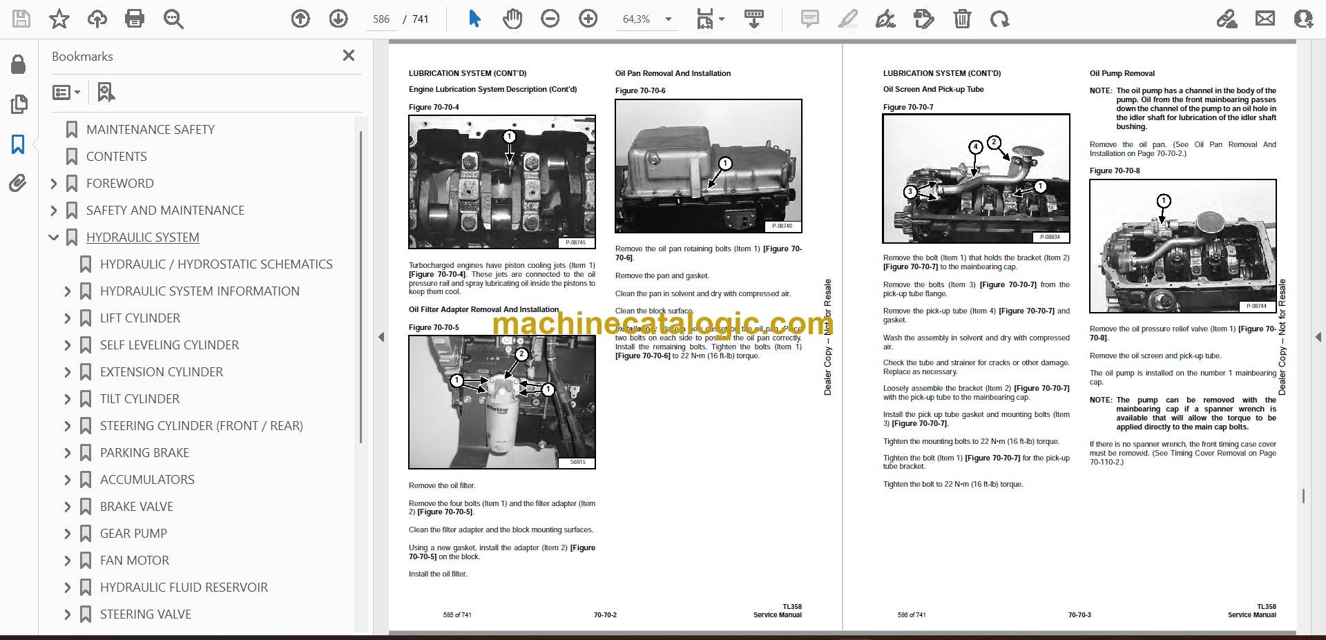
Q: Is this a searchable PDF and are the wiring diagrams readable?

A: Manuals like this are usually scanned or native PDFs you can search, and the wiring pages are designed to be zoomed in so you can follow circuits.

Q: Does it cover my exact TL358?

A: If your machine plate shows TL358 VersaHANDLER TTC with a serial between B3G411001 and B3G413999, this is the correct manual.

Q: Is this the right document for regular maintenance only?

A: It does include maintenance, but it's really aimed at full diagnostics and repair. For quick service intervals only, a maintenance or operator manual may be enough.

Bottom line, if your TL358 falls in that serial range and you're planning to actually wrench on it, this is the manual you want in the truck.

📘 Show Index

Table of Contents:

  • MAINTENANCE SAFETY
  • CONTENTS
  • FOREWORD
    • FOREWORD
    • SAFETY INSTRUCTIONS
      • Safe Operation Is The Operator’s Responsibility
      • Safe Operation Needs A Qualified Operator
      • Avoid Silica Dust
      • Dismantling And Disposal
    • FIRE PREVENTION
      • Maintenance
      • Operation
      • Electrical
      • Hydraulic System
      • Fueling
      • Starting
      • Welding And Grinding
      • Fire Extinguishers
    • SERIAL NUMBER LOCATION
      • Telescopic Handler Serial Number
      • Engine Serial Number
      • Other Serial Numbers
    • DELIVERY REPORT
    • BOBCAT TELESCOPIC HANDLER IDENTIFICATION
  • SAFETY AND MAINTENANCE
    • LIFTING AND BLOCKING THE TELESCOPIC HANDLER
      • Procedure
    • OPERATOR CAB
      • Description
      • Cab Door
      • Cab Door Window
      • Rear Cab Window
      • Cab Light
    • TRANSPORTING THE TELESCOPIC HANDLER ON A TRAILER
      • Loading And Unloading
      • Fastening
    • TOWING THE TELESCOPIC HANDLER
      • Procedure
    • SERVICE SCHEDULE
      • Maintenance Intervals
    • AIR CLEANER SERVICE
      • Replacing Filter Elements
    • ENGINE COOLING SYSTEM
      • Cleaning
      • Checking Level
      • Removing And Replacing The Coolant
    • FUEL SYSTEM
      • Fuel Specifications
      • Biodiesel Blend Fuel
      • Filling The Fuel Tank
      • Primary Fuel Filter (Pre-Filter)
      • Secondary Fuel Filter
      • Removing Air From The Fuel System
    • ENGINE LUBRICATION SYSTEM
      • Checking And Adding Engine Oil
      • Engine Oil Chart
      • Removing And Replacing Oil And Filter
    • HYDRAULIC / HYDROSTATIC SYSTEM
      • Checking And Adding Fluid
      • Hydraulic / Hydrostatic Fluid Chart
      • Removing And Replacing Hydraulic Fluid
      • Removing And Replacing Hydraulic / Hydrostatic Filters
      • Fill / Breather Cap
    • AXLES (FRONT AND REAR)
      • Checking And Adding Oil (Planetary Carrier)
      • Removing And Replacing Oil (Planetary Carrier)
      • Checking And Adding Oil (Rear Differential)
      • Removing And Replacing Oil (Rear Differential)
      • Checking And Adding Oil (Front Differential)
      • Removing And Replacing Oil (Front Differential)
      • Checking And Adding Oil (Reduction Box)
      • Removing And Replacing Oil (Reduction Box)
    • LUBRICATING THE TELESCOPIC HANDLER
      • Lubrication Locations
    • ATTACHMENT CARRIER
      • Inspection And Maintenance
    • TIRE MAINTENANCE
      • Wheel Nuts
      • Rotating
      • Wheel Replacement
      • Mounting
      • Pressure
    • APPROVED BOOM STOP
      • Installing The Approved Boom Stop
      • Removing The Approved Boom Stop
    • ENGINE COVER
      • Opening And Closing
    • STOPPING THE ENGINE AND LEAVING THE TELESCOPIC HANDLER
      • Procedure
    • EMERGENCY EXIT
      • Rear Window
    • TELESCOPIC HANDLER STORAGE AND RETURN TO SERVICE
      • Storage
      • Return To Service
    • LIFTING THE TELESCOPIC HANDLER
      • Procedure
    • REMOTE START TOOL (SERVICE TOOL) KIT – MEL1563
      • Remote Start Tool – MEL1563
      • Service Tool Harness Control – MEL1565
      • Service Tool Harness Communicator – MEL1566
    • REMOTE START TOOL (SERVICE TOOL) KIT – 7217666
      • Remote Start Tool (Service Tool) – 7022042
      • Telescopic Handler Service Tool Harness – 6689747
      • Computer Service Tool Harness – 6689746
      • Remote Start Procedure
  • HYDRAULIC SYSTEM
    • HYDRAULIC / HYDROSTATIC SCHEMATICS
    • HYDRAULIC SYSTEM INFORMATION
      • Glossary Of Hydraulic / Hydrostatic Symbols
      • Troubleshooting Chart
      • Tightening Procedures
    • LIFT CYLINDER
      • Removal And Installation
      • Parts Identification
      • Disassembly
      • Assembly
    • SELF LEVELING CYLINDER
      • Removal And Installation
      • Parts Identification
      • Disassembly
      • Assembly
    • EXTENSION CYLINDER
      • Removal And Installation
      • Parts Identification
      • Disassembly
      • Assembly
    • TILT CYLINDER
      • Removal And Installation
    • STEERING CYLINDER (FRONT / REAR)
      • Removal
      • Installation
      • Disassembly
      • Assembly
    • PARKING BRAKE
      • Valve Removal And Installation
    • ACCUMULATORS
      • Service Brake Accumulator Removal And Installation
      • Boom Suspension Valve Accumulators Removal And Installation
    • BRAKE VALVE
      • Removal And Installation
    • GEAR PUMP
      • Removal And Installation
      • Parts Identification
      • Disassembly And Assembly
    • FAN MOTOR
      • Removal And Installation
      • Parts Identification (Single Speed Version) (Standard)
      • Disassembly And Assembly (Single Speed Version) (Standard)
      • Parts Identification (Variable Speed Version) (Optional)
      • Disassembly And Assembly (Variable Speed Version) (Optional)
    • HYDRAULIC FLUID RESERVOIR
      • Removal And Installation
    • STEERING VALVE
      • Removal And Installation
    • HYDRAULIC CONTROL VALVE
      • Troubleshooting Chart (Solenoid Valves)
      • Valve Section Troubleshooting
      • Troubleshooting Chart (Control Valve)
      • Removal And Installation
      • Parts Identification
      • Section Removal
      • Section Disassembly And Assembly
      • Inlet-Outlet Valve Section Disassembly And Assembly
      • End Housing Disassembly And Assembly
    • PORT RELIEF VALVES
      • Removal And Installation
  • HYDROSTATIC SYSTEM
    • HYDROSTATIC SYSTEM INFORMATION
      • Troubleshooting Chart
    • OIL COOLER
      • Description
    • HYDROSTATIC DRIVE MOTOR
      • Removal And Installation
      • Parts Identification
      • Disassembly
      • Inspection
      • Assembly
    • HYDROSTATIC PUMP
      • Calibration
      • Removal And Installation
      • Parts Identification
      • Shaft Disassembly
      • Relief Valves Disassembly And Assembly
      • Charge Pump Disassembly
      • Piston Pump Disassembly
      • Solenoid Block Disassembly
      • Inspection
      • Piston Pump Assembly
      • Charge Pump Assembly
      • Solenoid Block Assembly
      • Shaft Assembly
  • DRIVE SYSTEM
    • DRIVE SYSTEM TROUBLESHOOTING
      • Chart
    • AXLE AND DIFFERENTIAL (FRONT)
      • Description
      • Planetary Carrier, Wheel Hub And Drive Axle Parts Identification
      • Planetary Carrier Disassembly
      • Wheel Hub Disassembly
      • Drive Axle Disassembly
      • Steering Knuckle Parts Identification
      • Steering Knuckle Disassembly
      • Brake Group Parts Identification
      • Brake Group Disassembly
      • Differential Parts Identification
      • Differential Disassembly
      • Pinion Group Parts Identification
      • Pinion Group Disassembly
      • Pinion Group Assembly
      • Differential Assembly
      • Brake Group Assembly
      • Axle Housing / Drive Axle Assembly
      • Steering Knuckle Assembly
      • Wheel Hub Assembly
      • Planetary Carrier Assembly
      • Special Tools
    • AXLE AND DIFFERENTIAL (REAR)
      • Description
      • Planetary Carrier, Wheel Hub And Drive Axle Parts Identification
      • Planetary Carrier Disassembly
      • Wheel Hub Disassembly
      • Steering Knuckle Parts Identification
      • Steering Knuckle Disassembly
      • Axle Housing / Drive Axle Disassembly
      • Differential And Pinion Group Parts Identification
      • Pinion Group Disassembly
      • Pinion Group Assembly
      • Differential Assembly
      • Steering Knuckle Assembly
      • Planetary Carrier Assembly
      • Special Tools
    • FRONT AXLE
      • Removal And Installation
    • AXLE TOE-IN
      • Adjustment
    • PARKING BRAKE
      • Parking Brake Removal, Disassembly And Assembly
    • STEERING ANGLE ADJUSTMENT
      • Adjustment
    • DRIVESHAFT
      • Removal And Installation
    • SERVICE BRAKE
      • Description
      • Bleeding The Brake Circuit
    • REAR AXLE
      • Removal And Installation
    • REDUCTION BOX
      • Removal And Installation
      • Parts Identification
      • Disassembly
      • Assembly
      • Special Tools
  • MAINFRAME
    • OPERATOR CAB
      • Removal And Installation
    • OPERATOR SEAT
      • Removal And Installation
    • BOOM ASSEMBLY
      • Removal And Installation
    • BOOM TRAY
      • Removal And Installation
      • Upper Tubeline Removal
      • Upper Tubeline Installation
      • Tubeline Tray Disassembly
      • Tubeline Tray Assembly
    • INNER BOOM
      • Removal
      • Installation
    • WEAR PADS (FRONT)
      • Removal
      • Installation
    • WEAR PADS (REAR)
      • Removal
      • Installation
    • ENGINE COVER
      • Gas Cylinder Removal And Installation
      • Removal And Installation
    • FUEL TANK
      • Removal And Installation
    • ATTACHMENT CARRIER (QUICK-TACH)
      • Removal And Installation
    • COUNTERWEIGHT
      • Removal And Installation
    • FENDER
      • Removal And Installation
    • STEERING COLUMN COVER
      • Removal And Installation
    • DASH COVER
      • Removal And Installation
    • JOYSTICK PANEL
      • Removal And Installation
  • ELECTRICAL SYSTEM AND ANALYSIS
    • ELECTRICAL SCHEMATICS
    • ELECTRICAL SYSTEM INFORMATION
      • Troubleshooting Chart
      • Description
      • Fuses And Relay Location / Identification
    • BATTERY
      • Removal And Installation
      • Using A Booster Battery (Jump Starting)
    • ALTERNATOR
      • Removal And Installation
      • Belt Adjustment
      • Belt Checking
      • Belt Replacement
    • STARTER
      • Testing
      • Removal And Installation
    • LIGHTS
      • Rear Light Removal And Installation
      • Rear Light Bulb Replacement
      • Front Light Removal And Installation
      • Front Light Bulb Replacement
    • SIGNAL LEVER
      • Removal And Installation
    • DISPLAY
      • Removal And Installation
    • INSTRUMENT PANEL
      • Removal And Installation
    • BOOM ANGLE SENSOR
      • Removal And Installation
      • Calibration
    • FRONT WIPER MOTOR
      • Removal And Installation
    • TOP WIPER MOTOR
      • Removal And Installation
    • REAR WIPER MOTOR
      • Removal And Installation
    • PEDAL ASSEMBLY
      • Removal And Installation
    • INCHING SENSOR
      • Removal And Installation
      • Calibration
    • SERVICE PC (LAPTOP COMPUTER)
      • Connecting Remote Start Tool (Service Tool) – MEL1563
      • Connecting Remote Start Tool (Service Tool) – 7217666
    • FUEL LEVEL SENDER
      • Removal And Installation
    • JOYSTICK
      • Removal And Installation
    • LLMI / LLMC SYSTEM
      • System Calibration
      • Calibration Test
      • System Failure Reports
      • System Components Identification
      • LLMS Removal
      • LLMS Installation
      • LLMC Removal And Installation
    • TRAVEL DIRECTION LEVER
      • Removal And Installation
    • CONTROLLERS
      • Description
      • Gateway Controller
      • Drive Controller
      • Workgroup Controller
      • Display Controller
      • LLMI Controller
      • LLMC Controller
  • ENGINE SERVICE
    • ENGINE INFORMATION
      • Specifications
      • Troubleshooting
      • Engine Removal And Installation
      • Compression Checking
    • ENGINE AND HYDROSTAT ASSEMBLY
      • Removal And Installation
    • ENGINE SPEED CONTROL
      • Removal And Installation
    • MUFFLER
      • Removal And Installation
    • AIR CLEANER
      • Housing Removal And Installation
    • ENGINE COOLING SYSTEM
      • Oil Cooler / Intercooler / Radiator Removal And Installation
      • Cooling System Description
      • Thermostat Removal And Installation
      • Thermostat Testing
      • Lubricating Oil Cooler Removal And Installation
      • Water Pump Removal
      • Water Pump Installation
      • Expansion Tank Removal And Installation
    • LUBRICATION SYSTEM
      • Engine Lubrication System Description
      • Oil Filter Adapter Removal And Installation
      • Oil Pan Removal And Installation
      • Oil Screen And Pick-up Tube
      • Oil Pump Removal
      • Oil Pump Installation
      • Oil Pump Disassembly And Assembly
      • Oil Pressure Relief Valve Disassembly And Assembly
    • FUEL SYSTEM
      • Fuel Injection Pump Removal
      • Fuel Injection Pump Installation
      • Fuel Injectors Removal And Installation
      • Checking The Fuel Lift Pump
      • Fuel Lift Pump Removal And Installation
      • Exhaust Manifold Removal And Installation
      • Fuel Injector Cover Removal And Installation
      • Rocker Cover Removal And Installation
    • CYLINDER HEAD
      • Glow Plugs Checking
      • Glow Plugs Removal And Installation
      • Removal
      • Inspection
      • Installation
      • Rocker Shaft Disassembly And Assembly
      • Valve Removal
      • Valve Springs Checking
      • Valve Depth Checking
      • Valve Guide Checking
      • Valve Guide Removal
      • Valve Guide Installation
      • Valve Checking
      • Cutting A Valve Seat
      • Valve Seat Assembly
      • Changing Valve Springs (With Cylinder Head Installed)
      • Valve Clearance Adjustment
      • Engine Block Description
      • Engine Block Disassembly And Assembly
      • Engine Block Inspection
      • Cylinder Liner Inspection
      • Cylinder Liner Removal
      • Cylinder Liner Installation
    • CRANKSHAFT AND PISTONS
      • Pistons And Connecting Rods Description
      • Pistons And Connecting Rods Removal
      • Pistons And Connecting Rods Disassembly
      • Piston Ring End Gap
      • Piston Ring Installation
      • Piston Ring Groove Clearance
      • Piston Cooling Jet Removal
      • Piston Cooling Jet Installation
      • Piston Cooling Jet Alignment
      • Connecting Rod Inspection
      • Connecting Rod Bushing Replacement
      • Piston And Connecting Rod Assembly
      • Piston And Connecting Rod Installation
      • Checking Piston Height
      • Crankshaft And Bearings Description
      • Crankshaft And Bearings Removal
      • Inspection Of Crankshaft And Bearings
      • Crankshaft And Bearings Installation
      • Rear Oil Seal Removal
      • Rear Oil Seal Housing Positioning
      • Rear Oil Seal Installation
      • Checking Crankshaft End Play
    • CAMSHAFT AND TIMING GEARS
      • Engine Timing Procedure
      • Timing Case And Drive Assembly Description
      • Timing Cover Removal
      • Timing Cover Installation
      • Crankshaft Pulley Removal And Installation
      • Front Oil Seal Removal And Installation
      • Timing Case And Gear Removal
      • Timing Case And Gear Installation
      • Camshaft And Tappets Removal
      • Camshaft And Tappets Installation
    • TURBOCHARGER
      • Troubleshooting
      • Description
      • Removal And Installation
    • FLYWHEEL AND HOUSING
      • Removal And Installation
      • Flywheel Inspection
      • Ring Gear Removal
      • Ring Gear Installation
  • HEATING, VENTILATION, AIR CONDITIONING (HVAC)
    • AIR CONDITIONING SYSTEM FLOW
      • Description
      • Chart
      • Components
      • Safety Equipment
    • REGULAR MAINTENANCE
      • Cab Filter
      • Belt Adjustment
      • Belt Replacement
      • Cleaning The Condenser
      • Air Conditioning Lubrication
      • Air Conditioning Service Chart
    • A/C SYSTEM TROUBLESHOOTING
      • Blower Motor Does Not Operate
      • Blower Motor Operates Normally, But Air Flow Is Insufficient
      • Insufficient Cooling Although Air Flow And Compressor Operation Are Normal
      • The Compressor Does Not Operate At All, Or Operates Improperly
      • Gauge Pressure Related Troubleshooting
      • Temperature / Pressure Chart
      • Poor A/C Performance
      • HVAC Repair And Leaks
      • Electrical System
    • SYSTEM CHARGING AND RECLAMATION
      • Reclamation And Charging With Recovery / Charging Unit
    • COMPRESSOR
      • Removal And Installation
      • Oil
      • Oil Check
      • Clutch Disassembly And Assembly
    • CONDENSER
      • Removal And Installation
    • RECEIVER / DRIER
      • Removal And Installation
    • PRESSURE SWITCH
      • Removal And Installation
    • EVAPORATOR / HEATER UNIT
      • Removal And Installation
    • THERMOSTAT
      • Description
      • Removal And Installation
    • EXPANSION VALVE
      • Removal And Installation
  • SPECIFICATIONS
    • TL358(D)(H) TELESCOPIC HANDLER SPECIFICATIONS
      • Machine Dimensions For Models TL358D
      • Machine Dimensions For Models TL358H
      • Performance
      • Weights
      • Engine
      • Controls
      • Drive System
      • Traction
      • Steering
      • Brakes
      • Fluid Capacities
      • Hydraulic System
      • Electrical System
      • Temperature Range
      • Altitude
      • Instrument Panel
    • TL358(D)(H)CW TELESCOPIC HANDLER SPECIFICATIONS
      • Machine Dimensions For Models TL358DCW
      • Machine Dimensions For Models TL358HCW
      • Performance
      • Weights
      • Engine
      • Controls
      • Drive System
      • Traction
      • Steering
      • Brakes
      • Fluid Capacities
      • Hydraulic System
      • Electrical System
      • Temperature Range
      • Altitude
      • Instrument Panel
    • MACHINE TORQUE SPECIFICATIONS
      • Axle
      • Boom
      • Reduction Box
      • Drive Motor
      • Engine
      • Hydraulic Pump
    • TORQUE SPECIFICATIONS FOR BOLTS
      • Torque for General SAE Bolts
      • Torque For General Metric Bolts
    • HYDRAULIC CONNECTION SPECIFICATIONS
      • O-ring Face Seal Connection
      • Straight Thread O-ring Fitting
      • Tubelines And Hoses
      • Flare Fitting
      • O-ring Flare Fitting
      • Port Seal Fitting
    • HYDRAULIC / HYDROSTATIC FLUID SPECIFICATIONS
      • Specifications
    • CONVERSIONS
      • Decimal And Millimeter Equivalent Chart
      • U.S. To Metric Conversion Chart
    • SERVICE TOOLS REQUIRED
      • Remote Start Tools
      • Hydraulic Tools
      • Drive Tools
      • Electrical Tools
      • Engine Tools
      • HVAC Tools
  • ALPHABETICAL INDEX

Bobcat Software

Bobcat PDF Manuals

Related Manuals

0
    0
    Your Cart
    Your cart is emptyReturn to Shop