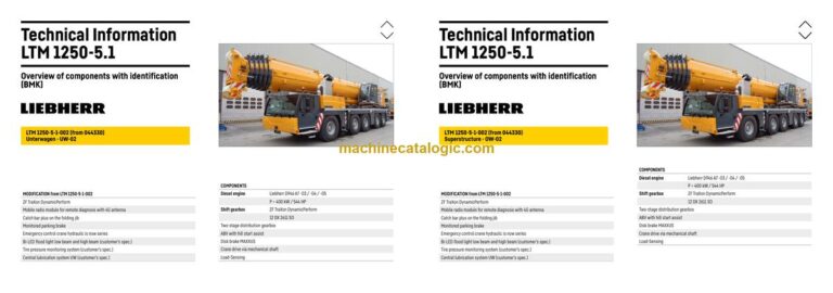
The Liebherr LTM 1250-5.1 Mobile Crane works hard on big lifts where downtime is expensive, so knowing exactly where each component sits is a big deal. The Technical Information & BMK Components Manual for Liebherr LTM 1250-5.1 Mobile Crane provides component identification diagrams, reference designators, and visual outlines used by technicians cross‑referencing wiring or hydraulic schematics to physical parts on the crane. This is the document your techs grab when a schematic says “K15” or “X45” and they need to find it on the real machine. It’s not for “how to fix it,” it’s for “where is it and what does Liebherr call it?”
What this manual helps you do
- Identify electrical and hydraulic components by their BMK codes and Liebherr names on the LTM 1250-5.1.
- Locate specific items on the carrier or superstructure using layout views and outline diagrams.
- Trace a reference designator from wiring or hydraulic diagrams to its physical mounting point.
- Cross-reference components between this BMK, service information, and parts catalogues for the same crane.
- Pinpoint fault-related components when a code or schematic points to a relay, sensor, or valve.
Who this is for
This is aimed at workshop technicians, field service techs, electrical diagnostic engineers, fleet mechanics, and training instructors working on SN 044501 machines. If you need repair procedures, torque specs, or part numbers, you want a service manual or parts catalogue instead of this BMK component identification manual.
FAQ
Q: Are the diagrams clear and searchable?
A: Yes, these PDFs are usually clean scans or native files with readable component labels and can typically be searched by BMK code or text.
Q: Does it cover both the carrier and the superstructure?
A: Yes, this product combines BMK information for the carrier and the superstructure into one manual.
Q: Does it work with other Liebherr documents?
A: Yes, these BMK codes are meant to match items in Liebherr wiring diagrams, hydraulic schematics, service manuals, and parts catalogues.
Bottom line: If your main question is “where is this component and what’s its Liebherr ID?”, this is exactly what you need. If your main question is “how do I repair or order it?”, this is not the right book.
📘 Show Index
Table of Contents:
Carrier — Table of Contents
- Table of contents
- Chassis:
- Lighting front and mirrors
- Lighting rear
- Side marker lights right
- Side marker lights left
- Sockets, warning signal sensor
- Back-up camera
- Earth- / distributor connector in the wiring loom W6
- Earth- / distributor connector in the wiring loom W7 / W146*
- Driver cab:
- Doors and windows, interior lighting
- Screen wiper and – washer, heating valves
- Ventilation and heat exchanger
- Control elements, seats
- BTB, remote control module BTT
- Control elements centre console
- Telemetry FMS-interface
- Telemetry-modem, monitoring parking brake
- Driver cab – centre console:
- I/O- modules, BTB voltage supply
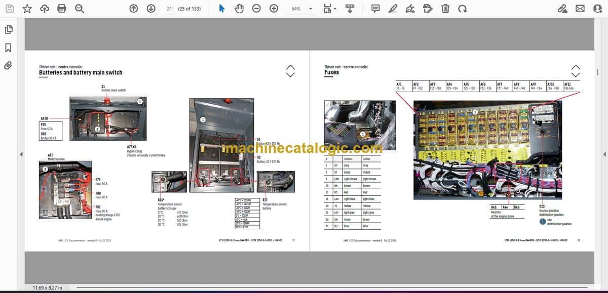
- Batteries and battery main switch
- Fuses
- Relays
- Voltage converter, heating flange – control
- Components, control unit
- Fan, EMERGENCY STOP
- Diagnosis plug
- Air-conditioner:
- Overview electrical components
- Pneumatic system:
- Air compressor and air dryer
- Compressed air reservoir, trailer control valve*
- Pneumatic valves in the driver cab
- Brake relay valves and overload protection valve
- Overflow valve, metering points compressed air circuits
- Pressure sensor and pressure switch for axle suspension and brake system
- Solenoid valves auxiliary consumer
- Overview disk brake system
- Overview brake pad monitoring
- Brake pad monitoring display
- ABV – Regulating valves / hill start assist
- ABV wheel speed sensors
- Drive assembly:
- Complete unit installation view
- View from right
- View from left
- Diesel engine D946 A7 -03 (eAGR) / -04 (SCRonly) / -05 (SCRF)
- Engine control unit
- Overview injection side
- Fuel pumps
- Fuel low pressure sensors
- Liebherr diesel injection system Daisy-Chain
- Injectors LCR-I S2, type plate
- Overview exhaust gas side
- Charge air sensors and charge air preheating
- Exhaust gas flap
- Exhaust gas turbo charger with wastegate
- Overview flywheel side and generator
- Speed sensors
- Overview fan side
- Cooling agent
- Oil circuit
- Ambient temperature diesel engine
- Terminal resistor CAN-LIDEC (ECU-CAN2)
- Terminal resistor engine-CAN (ECU-CAN2)
- External exhaust gas return eAGR
- Intercooler temperature sensor
- Exhaust gas system “SCRonly”
- Overview
- AdBlue-injector and upstream-sensors
- Downstream sensors
- Exhaust gas system “SCRF”
- Overview
- AdBlue-injector and upstream-sensors
- Downstream sensors
- Exhaust after treatment SCRonly / SCRF
- Urea tank and tank sensor
- Pump module and AdBlue-lines
- Exhaust gas system
- Components diesel engine:
- Air filter system
- Diesel fuel system
- Cooling system
- ZF-shift gear box TraXon DynamicPerform 12 DX 2611 SO:
- Gearbox control
- Intarder
- Wet starting clutch
- Hydraulic supply:
- Overview hydraulic pumps
- Support and axle suspension
- Temperature sensor hydraulic oil, hydraulic oil tank
- Emergency control crane hydraulic – vehicle
- Emergency control crane hydraulic – support
- Drive train:
- Overview
- Distribution gear – Kessler VG 2700 (2-stage)
- Road/off-road switchover
- Switch over travel drive / crane drive (PTO)
- Crane drive
- Crane drive – angle gear box
- Transversal differential lock axle 2 and 3*
- Transversal differential lock axle 4 and 5
- Longitudinal differential lock and activation* axle 3
- Steering:
- Steering gear ZF-Servocom
- Oil supply steering circuit 1, deficiency monitoring
- Oil supply steering circuit 2
- Active rear axle steering:
- Flow and pressure monitoring
- CAN-valves
- Control block
- Measuring points
- Angle sensor
- Steering- and centering cylinder, safety valves
- Support
- Inclination sensor
- Support valves – right
- Support valves – left
- Extension cylinder sliding beam
- Support cylinder
- VarioBase
- Sliding beam monitoring
- Axle suspension:
- Level sensor- axle suspension
- Pneumatic valves for axle suspension
- Valve block – axle suspension right
- Valve block – axle suspension left
- Axle suspension cylinder
- Special equipment:
- Eddy currant brake Telma Focal 2200*
- Additional heating Thermo Pro 90*
- Additional heating Air Top 2000 ST* and fuel tank*
- Engine preheating* Air Top EVO 55 / Thermo Top Pro 150
- Cooling water preheating*
- External power supply 110 V / 230 V*
- Compensation axle suspension*
- Switch over bladder accumulator right*
- Switch over bladder accumulator left*
- Braking force reduction*
- Battery charger*
- Central lubrication system*
- Additional floodlight sidewise and rear*
- Attachment:
- Index
- Limitation of liability / Disclaimer
Superstructure — Table of Contents
- Inhaltsverzeichnis
- Oberwagen allgemein:
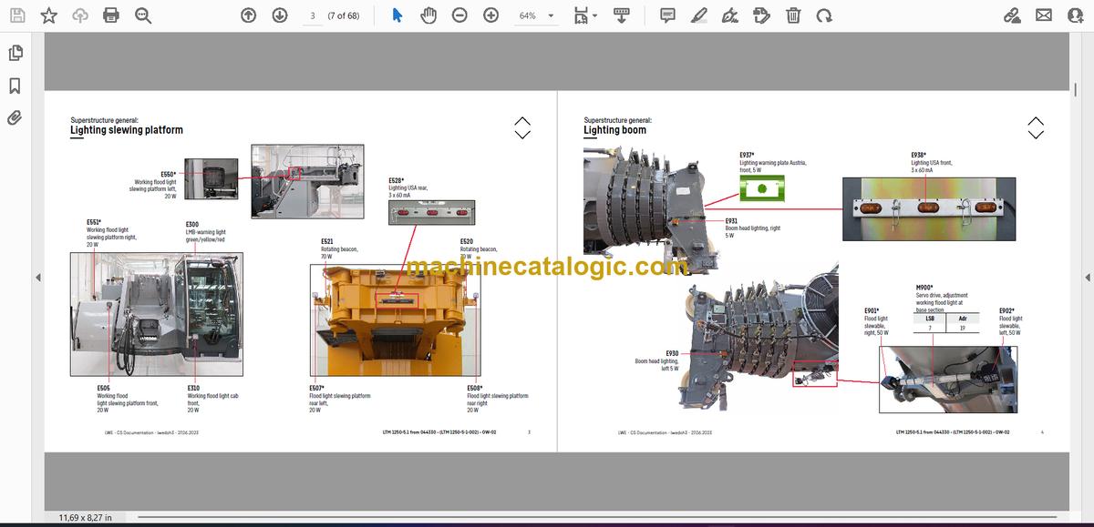
- Beleuchtung Drehbühne
- Beleuchtung Ausleger
- LMB-Warneinrichtung (EN 13000)
- Zentralschmieranlage
- Krankabine:
- Heizung – Heizklimagerät
- Heizung – Zusatzheizung Thermo Pro 90
- Heizung – Ansteuerung, Temperatursensoren
- Klimaanlage
- Wischermotoren, Waschpumpe
- Innenausstattung
- Podest Kabine
- Armaturen Kabine:
- LICCON-Monitor, Pedale
- Meisterschalter 1, LSB-TE1 rechts
- Meisterschalter 2, LSB-TE2 links
- Bedien- und Kontrolleinheit
- Schaltschrank Krankabine:
- Schwenkrahmen – Sicherungen
- Relais, Widerstandsmodul
- Montageblech – LSB-Master, Spannungswandler
- Universelles Ein- und Ausgabemodul UEA, Datenlogger II
- Diagnosestecker, Ferndiagnose
- NOTBETRIEB – XNOT-Stecker
- NOTBETRIEB Widerstände
- Kranantrieb:
- Mechanische Welle
- Winkelgetriebe
- Verteilergetriebe
- Kranhydraulik:
- Übersicht Hydraulikpumpen
- Übersicht Hydraulikkomponenten
- Übersicht Messanschlussplatte
- Hauptsteuerblock
- Druckgeber und Stellungsüberwachung
- Teleskopzylinder – Vorspannung
- Drehwerk – Ansteuerung, Bremse
- Drehwerk, Drehwertgeber
- Wippwerk
- Hubwerk 1
- Hubwerk 2*
- Hubwerk 2* – Anschlüsse
- Ventilblock Nebenverbraucher
- Kippzylinder Kabine, Drehbühnenarretierung
- VarioBallast: Ballastierung links
- VarioBallast: Ballastierung rechts
- Ballastüberwachung
- Temperaturgeber und Ölkühler
- Ölfilter
- Notbetätigung Kranhydraulik
- Teleskopausleger:
- Anlenkstück
- Auslegerkopf
- Ausschubmechanik (Telematik) – Zylinderposition, Teleteilverbolzung
- Ausschubmechanik (Telematik) – Zylinderverbolzung
- Notbetrieb Tele- / Zylinderverbolzung
- Sonderausstattung:
- Klappspitze* – Elektrik
- Klappspitze* – Hydraulik
- Hydraulische Klappspitze* – Schlauchtrommel
- Kamera Winden*
- Hydraulisch verstellbare feste Gitterspitze TF*
- Dollybetrieb Drehbühne rechts*
- Dollybetrieb Drehbühne links*
- Ölvorwärmung*
- Wegfahrsperre*
- Anhang:
- Index
- Haftungsbegrenzung / Disclaimer
Liebherr Crane


