$ 0
0
$ 0
0

Mustang 850R and 2012 Skid Steer Loader Operator Manual

Format: PDF (Printable Document)

File Language: English

File Size: 12.13 MB (Speed Download Link)

Brand: Mustang

Models: 850R and 2012

Machine Type: Skid Steer Loader

Publication No.: 917397 (Rev. H)

Edition Date: May 2021

Type of Document: Operator Manual (operation, controls, safety and routine maintenance)

Searchable: Yes, text is searchable and copyable

Delivery: Instant download after payment

Categories: ,

$ 40

Share:

Mustang 850R and 2012 Skid Steer Loader Operator Manual

Most small skid steers I get in for resale come without the book, and the first thing a buyer asks is how often to grease it. This operator manual for the Mustang 850R and 2012 answers that and the rest of the daily routine.

It is publication 917397, Rev. H, dated May 2021, in English. It covers the 850R and the 2012, and the contents carry a section for the 2012 (EU) as well. It starts with Introduction and Loader Identification, then moves through Safety, Controls and Safety Equipment, Operation and Service.

What this manual helps you do

  • Start with the Control/Indicator Symbols section so every light and symbol on the panel is known before the first run.
  • Operate the loader by the Controls and Safety Equipment and Operation sections.
  • Check the Maintenance Schedule and the Maintenance Interval Chart for what is due and when.
  • Grease the points on the Figure 28 interval, every 10 hours or daily.
  • Look up chaincase oil, engine oil and the engine oil filter in the lubrication pages, and the Torque Specifications and Specifications sections for loader and dimensional figures.

Who this is for

Fits a dealer or owner-operator who has just taken over an 850R or 2012 and needs the daily checks and service routine written down. Also useful for a rental fleet handing the machine to a new operator.

Print the maintenance chart and keep it in the cab.

Preview of the Mustang 850R and 2012 Skid Steer Loader Operator Manual (PDF, sample pages)

Does this manual fit your machine?

Mustang models 850R and 2012
Machine type Skid Steer Loader
Publication No. 917397 (Rev. H)
Edition date May 2021

Check the model and serial number on your machine’s serial plate before ordering.

What’s inside

  • Troubleshooting: Troubleshooting
  • Torque values: Torque Specifications
  • Maintenance intervals / schedule: Figure 28 Grease Every 10 Hours (or daily); Maintenance Schedule; Maintenance Interval Chart
  • Lubrication, oils, fluids and capacities: Chaincase Oil; Engine Oil; Engine Oil Filter
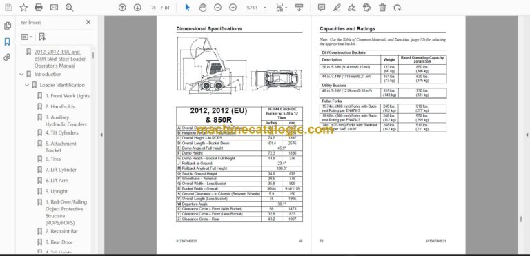
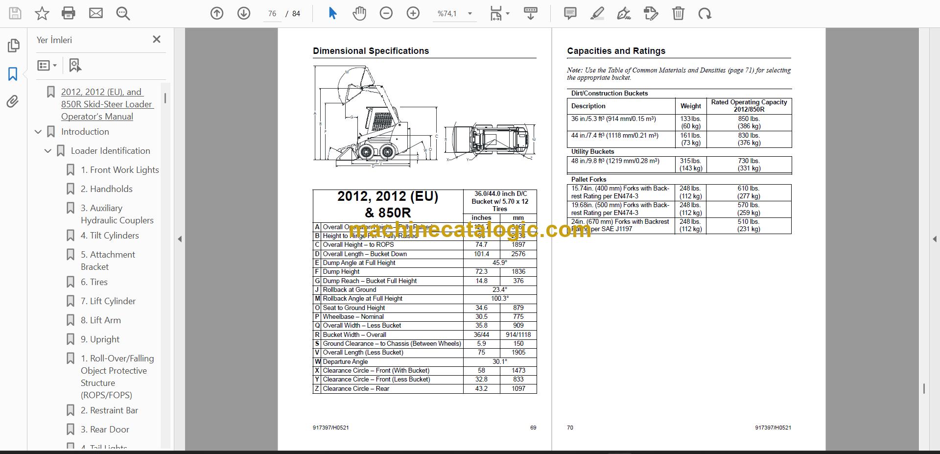
  • Technical specifications: Specifications; Loader Specifications; Dimensional Specifications
  • Adjustments and calibration: Adjustments

FAQ

Where do I find the service intervals?
Open the Maintenance Schedule section and the Maintenance Interval Chart. The grease interval of every 10 hours or daily is shown in Figure 28.

Does it cover oil and filter details?
Yes, the lubrication pages list Chaincase Oil, Engine Oil and the Engine Oil Filter.

Which section helps when something is not working right?
Go to Troubleshooting. The Adjustments section is there for setting things back where they belong.

Where are the machine specifications and torque figures?
Specifications holds Loader Specifications and Dimensional Specifications. Torque Specifications is a separate section.
📘 Show Index

Table of Contents:

  • Introduction
    • Loader Identification
    • Control/Indicator Symbols
      • Power Off
      • Power On
      • Engine Start
      • Hazard Flasher
      • Worklight
      • Worklight w/Flasher
      • Battery Charge
      • Parking Brake
      • Horn
      • Volume – Full
      • Volume – Half Full
      • Volume – Empty
      • Pre-Heat
      • Diesel Fuel
      • Lift Point
      • Neutral
      • Safety Alert
      • Chaincase Oil
      • Seatbelt – Lap Only
      • Engine Air Filter
      • Engine Oil
      • Engine Oil Filter
      • Engine Oil Pressure
      • Fuel Filter
      • Engine Coolant Temperature
      • Hydraulic System
      • Hydraulic Oil Temperature
      • Hydraulic Oil Filter
      • Grease Lubrication Point
      • Tie-Down
      • Machine Travel – Forward
      • Machine Travel – Reverse
      • Clockwise Rotation
      • Counterclockwise Rotation
      • Fast
      • Slow
      • Bucket – Lower
      • Bucket – Raise
      • Bucket – Float
      • Bucket – Rollback
      • Bucket – Dump
    • Safety
      • Mandatory Safety Shutdown Procedure
      • Safety Reminders
      • Potential Hazards
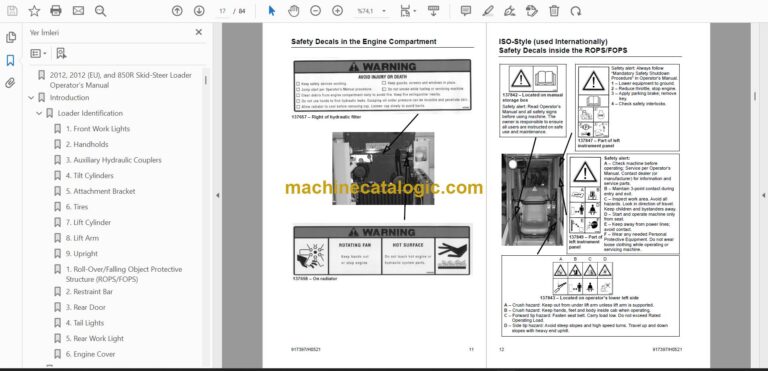
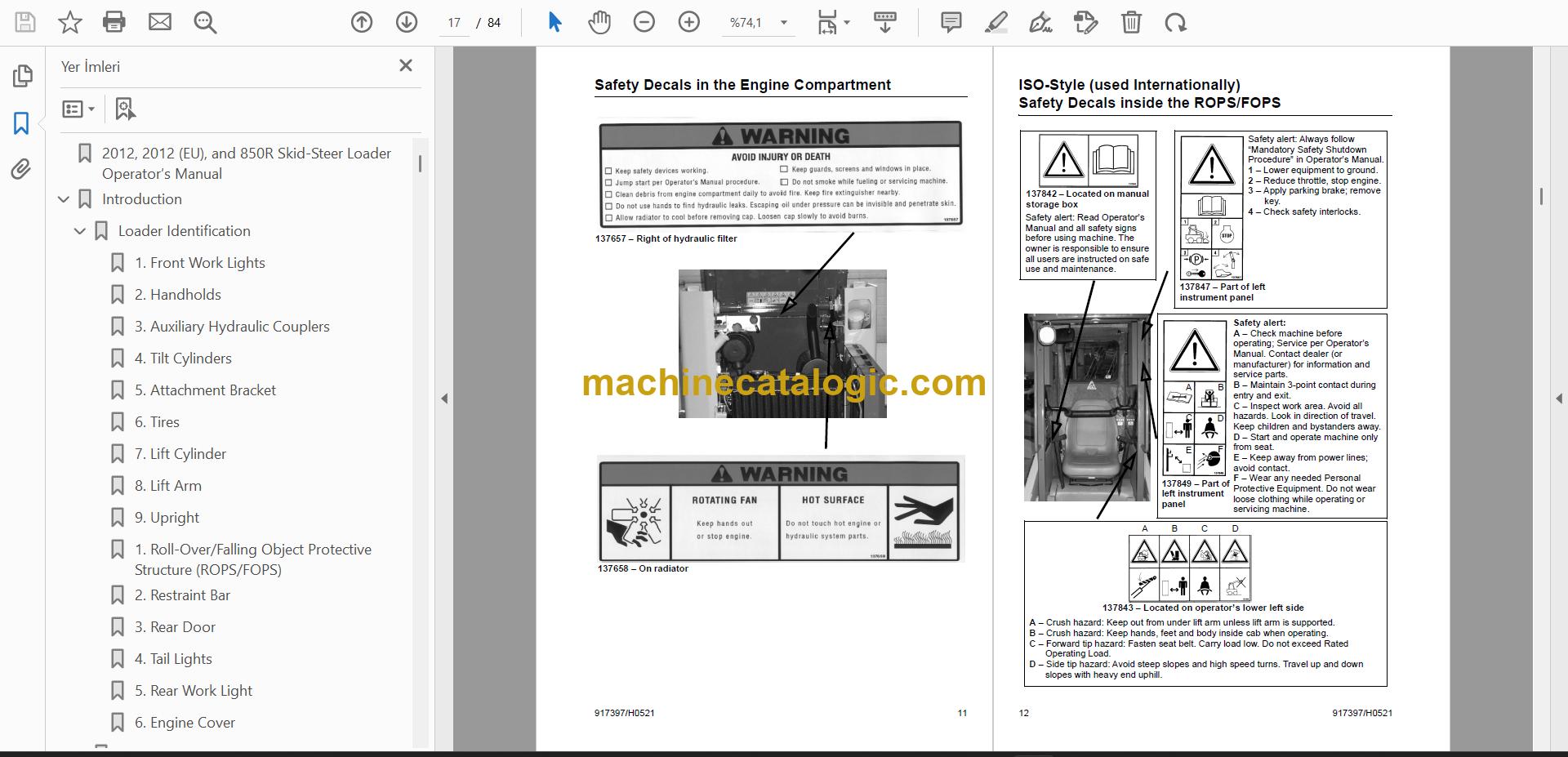
      • Safety Decals
        • New Decal Application
      • Safety Decals inside the ROPS/FOPS
      • Safety Decals in the Engine Compartment
      • ISO-Style (used Internationally) Safety Decals inside the ROPS/FOPS
      • ISO-Style (used Internationally) Safety Decals in the Engine Compartment
      • Product and Component Plate Locations
    • Controls and Safety Equipment
      • Guards and Shields
      • Operator Restraint Bar
      • Operator’s Seat
        • Figure 1 Operator’s Seat
      • Safety Interlock System
        • Testing the Safety Interlock System
      • ROPS/FOPS
      • Parking Brake
        • Figure 2 Parking Brake Switch
      • Rear Window Emergency Exit
        • Figure 3 Rear Window Emergency Exit Pull Tag
      • Lift Arm Support Device
        • Engagement
        • Figure 4 Lift Arm Support Device Engaged
        • Disengagement
        • Figure 5 Lift Arm Support Device In Storage Position
      • Accessory Outlet
      • Engine Speed Control
        • Figure 6 Throttle Lever
        • Figure 7 Foot Pedal
      • Right Instrument Panel
        • Figure 8 RIght Instrument Panel
      • Left Instrument Panel
        • Figure 9 Left Instrument Panel
      • T-Bar Controls
        • Figure 10 T-Bar Controls
        • Drive Controls
        • Lift/Tilt Control
      • Auxiliary Hydraulic System
        • Figure 11 Auxiliary Couplers
        • Figure 12 T-Bar Auxiliary Control
      • Attachment Mounting
        • Figure 13 Power-A-Tach™ Bracket Mechanism (Hitch)
    • Operation
      • Before Starting the Engine
      • Starting the Engine
      • Cold Starting Procedure
        • Figure 14 Preheat Button
      • Stopping the Loader
      • Parking the Loader
      • Jump Starting the Engine
      • Changing Attachments
        • Connecting an Attachment
        • Figure 15 Hitch – disengaged
        • Connecting Auxiliary Hydraulic Couplings
        • Removing Attachments
      • Self-Leveling (optional)
      • Using a Bucket
        • Driving Over Rough Terrain
        • Driving On an Inclin
        • Loading a Bucket
        • Figure 16 Loading
        • Digging with a Bucket
        • Figure 17 Digging
        • Dumping the Load onto a Pile
        • Dumping the Load Into a Box
        • Figure 18 Dumping Into a Box
        • Dumping the Load Over an Embankment
        • Scraping with a Bucket
        • Figure 19 Scraping
        • Leveling the Ground
        • Figure 20 Leveling the Ground
      • Highway Travel
      • Lifting the Loader
        • Figure 21 ROPS/FOPS Lift Point
        • Figure 22 Chassis Lift Point
      • Storing the Loader
      • Transporting the Loader
        • Figure 23 Front Tie Down/Retrieval Point
        • Figure 24 Rear Tie Down/ Retrieval Point
    • Service
      • Dealer Services
        • Figure 25 Engine Compartment
      • Tilting Back the ROPS/FOPS
        • Figure 26 ROPS Lock Mechanism
      • Loader Raising Procedure
      • Loader Lowering Procedure
        • Figure 27 Blocked Loader
      • Replacement Parts
      • Adjustments
        • Control Handles
        • Fuel Sender
        • Engine Speed Control
        • Drive Chains
      • Lubrication
        • Figure 28 Grease Every 10 Hours (or daily)
      • Engine Air Cleaner
        • Figure 29 Dual-Element Air Cleaner
        • Access
        • Outer Element
        • Inner Element
        • Reinstallation
      • Engine Service
        • Check Engine Mounting Hardware
        • Checking Engine Oil Level
        • Figure 30 Oil Dipstick and Fill Cap
        • Changing Engine Oil and Filter
        • Figure 31 Rear Belly Pan
        • Changing Fuel Filter
        • Servicing Water Separator
        • Releasing Water from Separator
      • Spark Arrestor Muffler
      • Alternator/Fan Belt
      • Hydraulic System
        • Checking Hydraulic Oil Level
        • Figure 32 Hydraulic Oil Service
        • Changing Hydraulic Oil Filter
        • Figure 33 Drain Plug
        • Changing Hydraulic Oil
      • Cooling Systems
        • Checking Coolant Level
        • Figure 34 Cooling System
        • Cleaning Cooling System
        • Draining/Flushing Cooling System
        • Figure 35 Check Plug
      • Chaincases
        • Figure 36 Drain Plugs
        • Checking and Adding Oil
        • Draining Oil
      • Seat and Restraint Bar Switches
      • Bucket Cutting Edge
      • Wheel Nuts
      • Tires
        • Mounting Tires
        • Checking Tire Pressure
      • Electrical System
        • Circuit Breakers
        • Battery
    • Troubleshooting
    • Maintenance Schedule
      • Maintenance Interval Chart
      • Maintenance Log
    • Specifications
      • Loader Specifications
      • Standard Features
      • Optional Features
      • Dimensional Specifications
    • 2012, 2012 (EU)
    • & 850R
      • 36.0/44.0 inch D/C Bucket w/ 5.70 x 12 Tires inches mm
      • Capacities and Ratings
        • (386 kg)
        • (376 kg)
        • (331 kg)
        • (277 kg)
        • (259 kg)
        • (231 kg)
      • Table of Common Materials and Densities
        • Bucket Selections
      • Torque Specifications
      • Index

Mustang PDF Manuals

Related Manuals

0
0
Your Cart
Your cart is emptyReturn to Shop