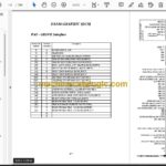
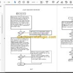
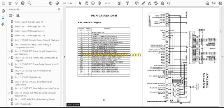
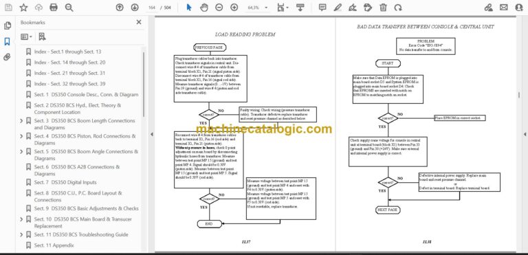
The PAT DS 350 is a load moment indicator, the system on a crane that watches the load against the boom's rated limits and warns the operator before it gets out of range. This manual is used on Grove machines. When the console throws a fault, a sensor reads wrong, or a board needs swapping, the person with the tools in hand needs wiring diagrams and a fault list, not guesswork. That's who reaches for a service manual like this one.
What this manual helps you do
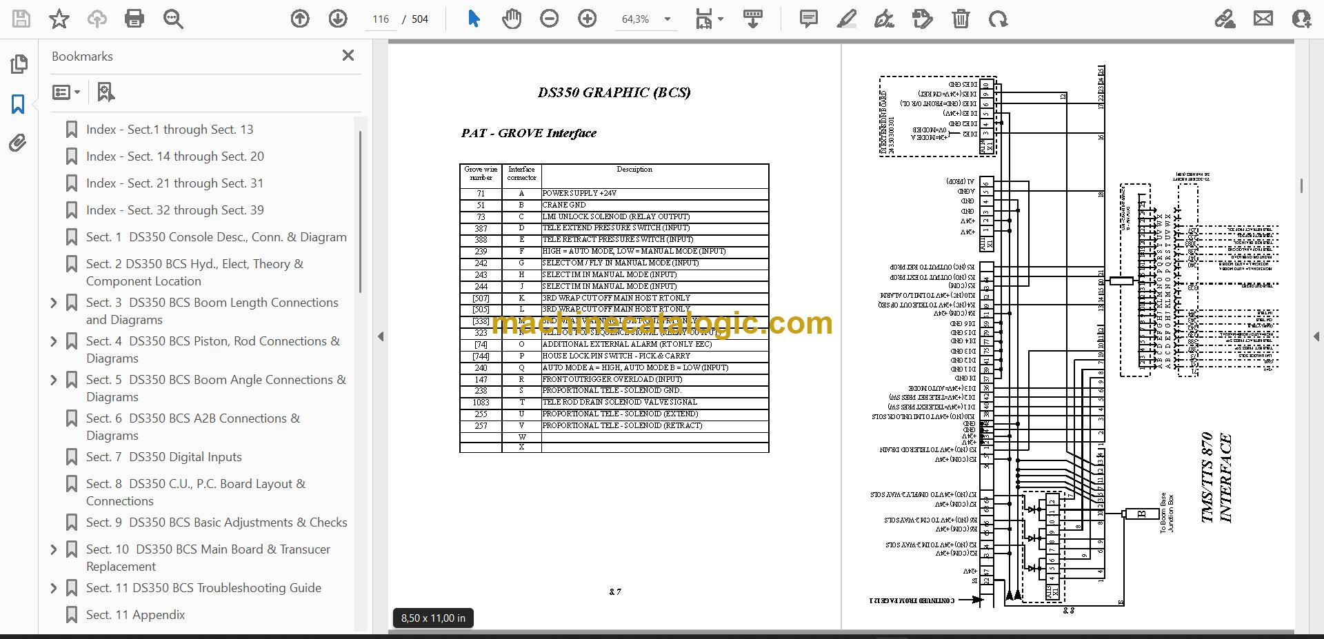
- Trace console, central unit and boom length connections using the wiring diagrams in the DS350 sections.
- Check piston, rod and boom angle sensor connections against the diagrams.
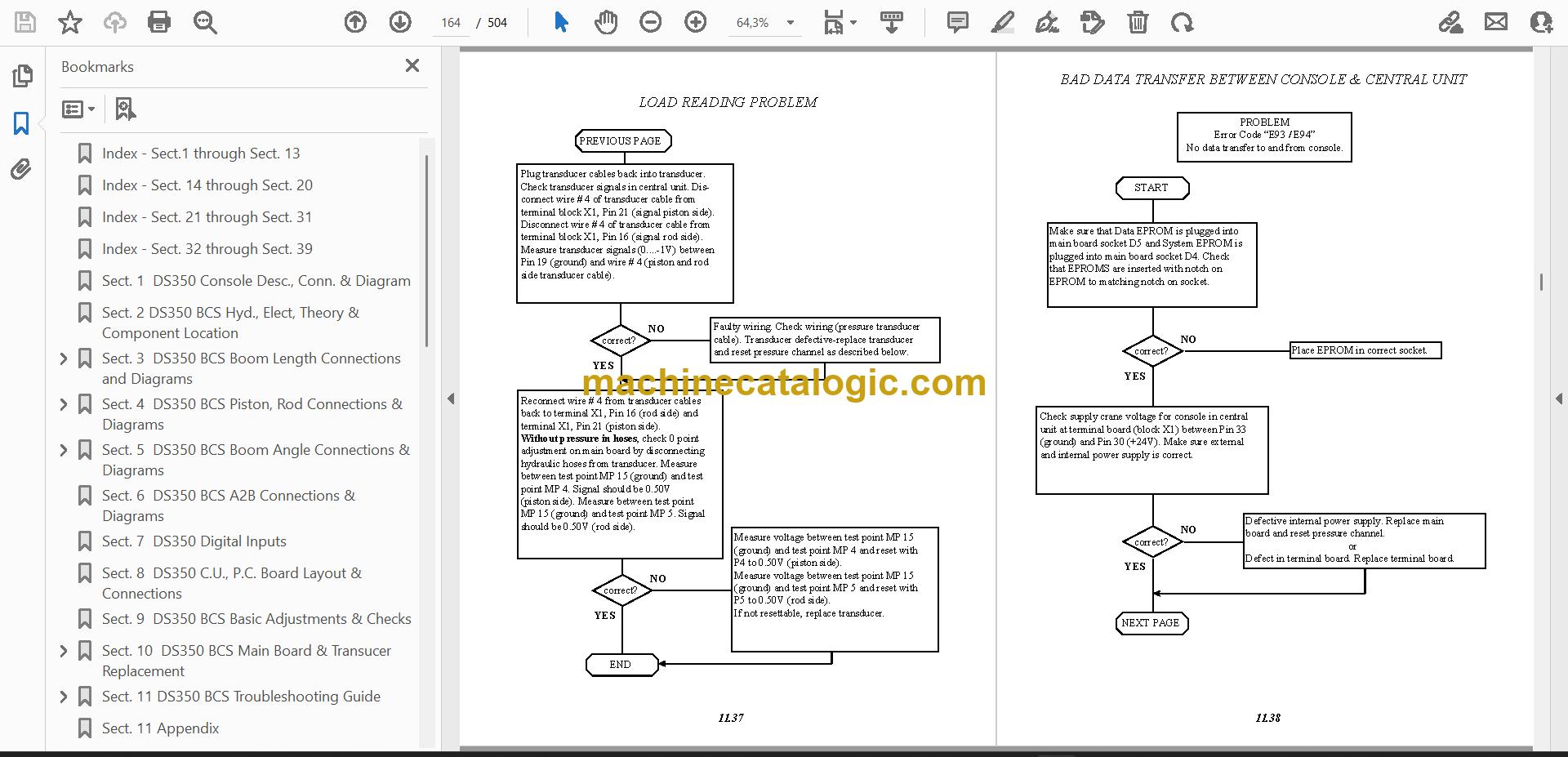
- Diagnose faults with the DS350 graphic modular troubleshooting guide and the iFLEX5 error code listing.
- Replace the main board and transducer on a DS350 BCS system.
- Follow the iFLEX5 software transfer instructions and the sensor troubleshooting steps using the display.
Who this is for
A crane service technician, rental fleet mechanic or independent repair shop that maintains LMI systems in-house. It also suits a dealer technician who has a machine come in with no paperwork and needs to find where a wire goes.
FAQ
Q: What do I receive and how is it organised?
A: You get one PDF file of 504 pages in English. The text is searchable, so you can jump straight to a connector, board or error code. It has an index and numbered sections running from the DS350 console through to iFLEX5 service information.
Q: Which system does it fit?
A: It covers the PAT DS 350 and also iFLEX5. The title reads "PAT Level II DS350 Graphic iFlex5 System Manual."
Q: How does it fit the job I'm doing?
A: If you're chasing a fault, replacing a board or transducer, or checking wiring on a DS350 or iFLEX5 system, the diagrams, board layouts and troubleshooting sections are where you'd look. You can search the PDF at the bench instead of paging through paper.
Download it, open the section for your system, and work from the diagrams and fault listings.
Click here to view the preview (PDF)
Models covered by this manual
This service manual is also used for one further Load Moment Indicator model: iFLEX5. Check the model and serial number on your data plate before ordering.
📘 Show Index
Table of Contents:
- Index – Sect.1 through Sect. 13
- Index – Sect. 14 through Sect. 20
- Index – Sect. 21 through Sect. 31
- Index – Sect. 32 through Sect. 39
- Sect. 1 DS350 Console Desc., Conn. & Diagram
- Sect. 2 DS350 BCS Hyd., Elect, Theory & Component Location
- Sect. 3 DS350 BCS Boom Length Connections and Diagrams
- Sect. 4 DS350 BCS Piston, Rod Connections & Diagrams
- E12 Error Code Procedure to Check Piston Pressure Transducer System
- E13 Error Code Procedure to Check Rod Pressure Transducer System
- Sect. 5 DS350 BCS Boom Angle Connections & Diagrams
- Sect. 6 DS350 BCS A2B Connections & Diagrams
- Sect. 7 DS350 Digital Inputs
- Sect. 8 DS350 C.U., P.C. Board Layout & Connections
- Sect. 9 DS350 BCS Basic Adjustments & Checks
- Sect. 10 DS350 BCS Main Board & Transucer Replacement
- Piston Pressure Channel Zero Point Adjustment
- Rod Pressure Channel Zero Point Adjustment
- Sect. 11 DS350 BCS Troubleshooting Guide
- Lever Lockout Activated
- Broken Length Cable
- No Display
- Sect. 11 Appendix
- Sect. 12 DS350 Graphic BCS Electrical Diagram
- TMS/TTS870 Wiring Connections
- Wiring Connections
- Sect. 13 Service Bulletins & Misc. Information
- Graphic Console Jumper Connection
- Sect. 14 DS350 Graphic Modular Console Connections & Diagrams
- Sect. 15 DS350 Graphic Modular Central Unit, P.C. Board Layout & Connections
- DS350 Graphic Modular Basic Adjustments & Voltage Checks
- Sect. 16 DS350 Graphic Modular Boom Length Connections & Diagrams
- Sect. 17 DS350 Graphic Modular Piston, Rod, Connections & Diagrams
- Sect. 18 DS350 Graphic Modular Boom Angle Connections & Diagrams
- DS350 Graphic Modular Slewing Angle
- Sect. 19 DS350 Graphic Modular Anti-2-Block Connections & Diagrams
- Sect. 20 DS350 Graphic Modular Troubleshooting Guide
- Lever Lockout Activated
- Broken Length Cable
- No Display
- Sect. 21 DS350 Graphic Modular (BCS) Console Connections & Diagrams
- Sect. 22 DS350 Graphic Modular (BCS) System Theory & Component Location
- Sect. 23 DS350 Graphic Modular (BCS) Boom Length Connections & Diagrams
- Sect. 24 DS350 Graphic Modular (BCS) Piston, Rod Connections & Diagrams
- Sect. 25 DS350 Graphic Modular (BCS) Boom Angle Connections & Diagrams
- Sect. 26 DS350 Grapghic Modular (BCS) A-2-B Connections & Diagrams
- Sect. 27 DS350 Graphic Modular (BCS) Digital Inputs
- Sect. 28 DS350 Graphic Modular (BCS) Central Unit P.C. Board Layout
- Sect. 29 DS350 Graphic Modular (BCS) Troubleshooting Guide
- Lever Lockout Activated
- Broken Length Cable
- No Display
- Sect. 30 DS350 Graphic Modular (BCS) Electrical Diagrams
- Sect. 31 DS350 Graphic Modular (BCS) Bulletins & Misc. Info
- Sect. 32 iFLEX5 Service Information
- Sect. 33 iFLEX5 Troubleshooting a Sensor Problem Using the Display
- Sect. 34 iFLEX5 Service Screen for Sensor Calibration
- Sect. 35 iFLEX Boom Control
- Sect. 36 i FLEX5 Luffing Boom Extension
- Sect. 37 iFLEX5 Error Code Listing
- Sect. 38 iFLEX5 Troubleshooting Moisture
- Sect. 39 iFLEX5 Software Transfer Instructions Information
PAT PDF Manuals
All Crane Manuals