An LMI like the iFLEX5 watches crane loading and warns the operator as the machine nears its limits. When it throws a fault or a sensor reads wrong, someone has to find out why. That's the person who opens this manual: a technician working on a Grove crane who needs wiring diagrams, fault meanings and replacement steps in front of them.
What this manual helps you do
- Troubleshoot a sensor problem using the display, following the iFLEX5 sensor troubleshooting section.
- Look up iFLEX5 error codes and work back to the cause.
- Trace console, central unit and boom length connections against the wiring diagrams.
- Replace the main board and transducer using the DS350 BCS replacement section.
- Follow the software transfer instructions when a unit needs reloading.
Who this is for
A crane service technician, rental fleet mechanic or independent repair shop that maintains LMI systems on Grove cranes. It also suits a dealer technician handling a used machine that arrived with no paperwork.
FAQ
Q: What do I receive and how is it organised?
A: You get the set: 3 PDF files, 664 pages in total, in English. They are Publication 031-300-190-154 (79 pages), Manual 2 (81 pages) and Manual 3 (504 pages), which is the main manual. The text can be searched and copied, so you can jump straight to a fault code or a connector.
Q: Which system does it fit?
A: It is the PAT Level II DS350 Graphic iFlex5 System Manual, and it covers the iFLEX5 and the DS350. The cover may carry the older Hirschmann name, so don't be thrown by the logo.
Q: How does it fit the job I'm doing?
A: The sections run from system theory and component location through connections and diagrams, a troubleshooting guide, error code listing and service bulletins. That is the order you'd work in on a bench or at the crane.
If you're chasing an LMI fault or swapping a board, this gives you the diagrams and fault listings to do it.
Click here to view the preview (PDF)
Models covered by this manual
This service manual is also used for one further Load Moment Indicator model: DS 350. Check the model and serial number on your data plate before ordering.
📘 Show Index
Table of Contents:
- Manual 3 (504 pages)
- Index – Sect.1 through Sect. 13
- Index – Sect. 14 through Sect. 20
- Index – Sect. 21 through Sect. 31
- Index – Sect. 32 through Sect. 39
- Sect. 1 DS350 Console Desc., Conn. & Diagram
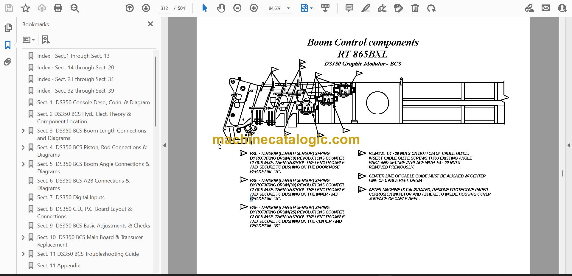
- Sect. 2 DS350 BCS Hyd., Elect, Theory & Component Location
- Sect. 3 DS350 BCS Boom Length Connections and Diagrams
- Sect. 4 DS350 BCS Piston, Rod Connections & Diagrams
- E12 Error Code Procedure to Check Piston Pressure Transducer System
- E13 Error Code Procedure to Check Rod Pressure Transducer System
- Sect. 5 DS350 BCS Boom Angle Connections & Diagrams
- Sect. 6 DS350 BCS A2B Connections & Diagrams
- Sect. 7 DS350 Digital Inputs
- Sect. 8 DS350 C.U., P.C. Board Layout & Connections
- Sect. 9 DS350 BCS Basic Adjustments & Checks
- Sect. 10 DS350 BCS Main Board & Transucer Replacement
- Piston Pressure Channel Zero Point Adjustment
- Rod Pressure Channel Zero Point Adjustment
- Sect. 11 DS350 BCS Troubleshooting Guide
- Lever Lockout Activated
- Broken Length Cable
- No Display
- Sect. 11 Appendix
- Sect. 12 DS350 Graphic BCS Electrical Diagram
- TMS/TTS870 Wiring Connections
- Wiring Connections
- Sect. 13 Service Bulletins & Misc. Information
- Graphic Console Jumper Connection
- Sect. 14 DS350 Graphic Modular Console Connections & Diagrams
- Sect. 15 DS350 Graphic Modular Central Unit, P.C. Board Layout & Connections
- DS350 Graphic Modular Basic Adjustments & Voltage Checks
- Sect. 16 DS350 Graphic Modular Boom Length Connections & Diagrams
- Sect. 17 DS350 Graphic Modular Piston, Rod, Connections & Diagrams
- Sect. 18 DS350 Graphic Modular Boom Angle Connections & Diagrams
- DS350 Graphic Modular Slewing Angle
- Sect. 19 DS350 Graphic Modular Anti-2-Block Connections & Diagrams
- Sect. 20 DS350 Graphic Modular Troubleshooting Guide
- Lever Lockout Activated
- Broken Length Cable
- No Display
- Sect. 21 DS350 Graphic Modular (BCS) Console Connections & Diagrams
- Sect. 22 DS350 Graphic Modular (BCS) System Theory & Component Location
- Sect. 23 DS350 Graphic Modular (BCS) Boom Length Connections & Diagrams
- Sect. 24 DS350 Graphic Modular (BCS) Piston, Rod Connections & Diagrams
- Sect. 25 DS350 Graphic Modular (BCS) Boom Angle Connections & Diagrams
- Sect. 26 DS350 Grapghic Modular (BCS) A-2-B Connections & Diagrams
- Sect. 27 DS350 Graphic Modular (BCS) Digital Inputs
- Sect. 28 DS350 Graphic Modular (BCS) Central Unit P.C. Board Layout
- Sect. 29 DS350 Graphic Modular (BCS) Troubleshooting Guide
- Lever Lockout Activated
- Broken Length Cable
- No Display
- Sect. 30 DS350 Graphic Modular (BCS) Electrical Diagrams
- Sect. 31 DS350 Graphic Modular (BCS) Bulletins & Misc. Info
- Sect. 32 iFLEX5 Service Information
- Sect. 33 iFLEX5 Troubleshooting a Sensor Problem Using the Display
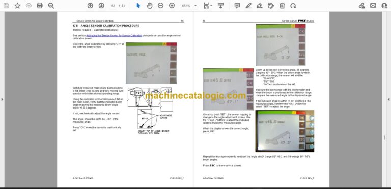
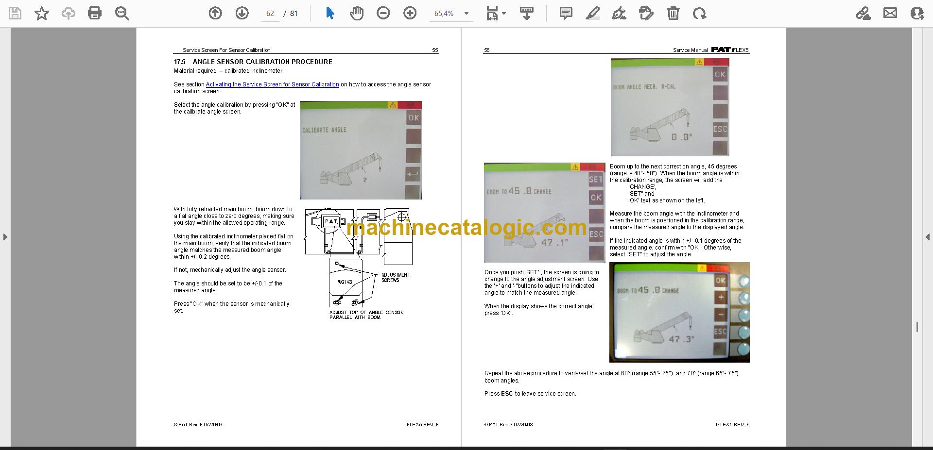
- Sect. 34 iFLEX5 Service Screen for Sensor Calibration
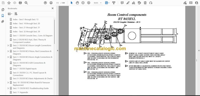
- Sect. 35 iFLEX Boom Control
- Sect. 36 i FLEX5 Luffing Boom Extension
- Sect. 37 iFLEX5 Error Code Listing
- Sect. 38 iFLEX5 Troubleshooting Moisture
- Sect. 39 iFLEX5 Software Transfer Instructions Information
- Publication 031-300-190-154 (79 pages)
- General Information
- Warnings
- Description Of The System
- DESCRIPTION OF SYSTEM FUNCTION
- DESCRIPTION OF A CAN BUS SYSTEM
- DESCRIPTION OF THE SYSTEM COMPONENTS
- What’s Wrong?
- Angle Sensing
- ANGLE SENSING ERROR – FLOW CHART
- Length Sensing
- LENGTH SENSING ERROR – FLOW CHART
- Pressure Sensing
- PRESSURE SENSING ERROR – FLOW CHART
- Slewing Sensing
- SLEW SENSING ERROR – FLOW CHART
- Load sensing
- LOAD SENSING ERROR – FLOW CHART
- No console display
- A2B Problem
- cann-bus communication
- Troubleshooting a sensor problem using the display
- iFLEX5 Boom Control System (BCS)
- RT800E BASICS
- Terminology
- Components
- Drawings
- COMPONENTS OF THE LMI SYSTEM PAT iFLEX5
- BLOCK DIAGRAM
- ELECTRICAL SYSTEM DIAGRAM STANDARD SYSTEM
- Spare Part Listings
- Service Screen For Sensor Calibration
- ACTIVATING THE SERVICE SCREEN FOR SENSOR CALIBRATION
- ZERO-SETTING THE TRANSDUCER INPUTS
- ZERO-SETTING THE SLEWING INPUTS
- Error Codes
- Troubleshooting Moisture
- WATER INGRESS
- CONDENSATION
- Manual 2 (81 pages)
- Service Manual
- iFLEX
- IFLEX 5 REV_F
- General Information
- Warnings
- Description Of The System
- DESCRIPTION OF SYSTEM FUNCTION
- DESCRIPTION OF A CAN BUS SYSTEM
- DESCRIPTION OF THE SYSTEM COMPONENTS
- What’s Wrong?
- I HAVE AN ERROR CODE INDICATED ON THE CONSOLE
- THE DISPLAYED ANGLE DOES NOT MATCH THE ACTUAL BOOM ANGLE
- THE DISPLAYED LENGTH DOES NOT MATCH THE ACTUAL BOOM LENGTH
- Angle Sensing
- Length Sensing
- Pressure Sensing
- Slewing Sensing
- Load sensing
- No console display
- A2B Problem
- CAN-Bus Communication
- Troubleshooting A Sensor Problem Using The Display
- iFLEX5 Boom Control System (BCS)
- RT800E BASICS
- TELE SEQUENCE
- IFLEX5 BCS DIGITAL INPUTS
- Drawings
- COMPONENTS OF THE LMI SYSTEM PAT IFLEX5
- BLOCK DIAGRAM
- ELECTRICAL SYSTEM DIAGRAM STANDARD SYSTEM
- Spare Part Listings
- GRAPHIC CONSOLE ASSY, VERTICAL PART NO. 9333103868
- WIRING HARNESS STANDARD, PART NO. 9333103869
- WIRING HARNESS BOOM CONTROL, PART NO. 9333103911
- Service Screen For Sensor Calibration
- ACTIVATING THE SERVICE SCREEN FOR SENSOR CALIBRATION
- ZERO-SETTING THE TRANSDUCER INPUTS
- ZERO-SETTING THE SLEWING INPUTS
- Error Codes
- Troubleshooting Moisture
- WATER INGRESS
- CONDENSATION
- Software Transfer Instructions for the Console Using the flash module
- Software Transfer Instructions for the iFLASH Palm and Central Unit
- INTRODUCTION
- INSTALLING IFLASH DESKTOP
- INSTALLING IFLASH
- REFERENCE
- Please go to sectionA2B PROBLEM
- Block Diagram
- Bus converter board (left)
- Pressure Transducer
- Angle
- Sensor
- CAN-Bus
- Converter
- Cable Ree
- CAN-Bus electronics in cable reel
- Terminal X
- Signal
PAT PDF Manuals
All Crane Manuals