A Bobcat 320 mini excavator is a tight-space digging machine, like the small Cats and Deeres you see on utility and landscape jobs. People grab the service manual when they're past warranty or they've bought a used unit and need more than guesswork. Around my shop, this is what we use when we're chasing hydraulic issues, doing engine work, or sorting out wiring instead of just swapping parts.
What this manual helps you do
- Diagnose hydraulic problems, check pressures, and trace leaks on the 320's excavator-class hydraulic system
- Follow teardown and reassembly steps for components like cylinders, swing motor, and final drives
- Troubleshoot electrical faults using wiring diagrams, connector callouts, and test procedures
- Set and verify adjustments on controls, linkages, and travel functions so the machine tracks straight and digs clean
- Replace major assemblies, then verify operation with the right test points and specs for this serial range
Who this is for
This is for a shop mechanic, small contractor, rental fleet, or owner-operator working on a Bobcat 320 with serial number between 223811001 and 223899999. If you just want to know how to run the machine or basic maintenance, you want the operator's handbook instead, not this service manual.
FAQ
Q: Is this a searchable PDF and are the wiring diagrams readable?
A: Yes, these manuals are usually scanned or native PDFs you can search, and the wiring diagrams are clear enough to zoom and follow circuits.
Q: How do I know it matches my machine?
A: Check your serial plate. If your 320 excavator serial falls between 223811001 and 223899999, this is the right book.
Q: Is this the right document if I'm doing real repairs, not just greasing and filters?
A: Yes, this is the workshop-level service manual, meant for actual repairs and diagnostics, not routine operator service.
Bottom line: If your 320's serial number is in that range and you're doing your own repairs, this is the manual you want. If the serial doesn't match, skip it.
📘 Show Index
Table of Contents:
- MAINTENANCE SAFETY
- ALPHABETICAL INDEX
- CONTENTS
- FOREWORD
- SAFETY INSTRUCTIONS
- SERIAL NUMBER LOCATIONS
- Excavator Serial Number
- Engine Serial Number
- DELIVERY REPORT
- BOBCAT EXCAVATOR IDENTIFICATION
- SAFETY AND MAINTENANCE
- LIFTING AND BLOCKING THE EXCAVATOR
- SWING LOCK
- LIFTING THE EXCAVATOR
- OPERATOR CAB
- Emergency Exit
- Cab Door
- Front Window
- TRANSPORTING THE EXCAVATOR
- TAILGATE
- Opening And Closing The Tailgate (S/N 223513558 & Below And 223812078 & Below)
- Adjusting The Tailgate Latch (S/N 223513558 & Below And 223812078 & Below)
- Opening And Closing The Tailgate (S/N 223513559 & Above And 223812079 & Above)
- Adjusting The Tailgate Latch (S/N 223513559 & Above And 223812079 & Above)
- Adjusting The Bumper
- SERVICE SCHEDULE
- AIR CLEANER SERVICE
- Daily Check
- Replacing The Filters
- HEATER AIR FILTERS
- Recirculation Filter
- Fresh Air Filter
- ENGINE COOLING SYSTEM
- Cleaning The Cooling System
- Checking Coolant Level
- Replacing The Coolant
- FUEL SYSTEM
- Fuel Specifications
- Filling The Fuel Tank
- Removing Water From The Fuel Filter
- Replacing The Fuel Filter
- Draining The Fuel Tank
- Removing Air From The Fuel System
- ENGINE LUBRICATION SYSTEM
- Checking Engine Oil
- Replacing Oil And Filter
- HYDRAULIC SYSTEM
- Checking And Adding Fluid.
- Diagnostic Couplers
- Replacing The Hydraulic Filter
- Replacing The Hydraulic Fluid (S/N 223512346 & Below and 223814376 & Below)
- Replacing The Hydraulic Fluid (S/N 223512347 & Above and 22384377 & Above)
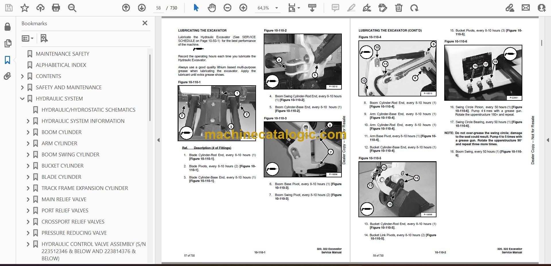
- LUBRICATING THE EXCAVATOR
- FINAL DRIVE CASE
- Checking Oil Level
- Draining Final Drive Case
- SPARK ARRESTOR MUFFLER
- HYDRAULIC SYSTEM
- HYDRAULIC/HYDROSTATIC SCHEMATICS
- HYDRAULIC SYSTEM INFORMATION
- BOOM CYLINDER
- Checking The Boom Cylinder
- Removal and Installation
- Parts Identification
- Disassembly
- Assembly
- ARM CYLINDER
- Checking The Arm Cylinder
- Removal and Installation
- Parts Identification
- Disassembly
- Assembly
- BOOM SWING CYLINDER
- Checking The Boom Swing Cylinder
- Removal and Installation
- Parts Identification
- Disassembly
- Assembly
- BUCKET CYLINDER
- Checking The Bucket Cylinder
- Removal and Installation
- Parts Identification
- Disassembly
- Assembly
- BLADE CYLINDER
- Checking The Blade Cylinder
- Removal and Installation
- Parts Identification
- Disassembly
- Assembly
- TRACK FRAME EXPANSION CYLINDER
- Checking The Track Frame Expansion Cylinder
- Removal And Installation
- Parts Identification
- Disassembly
- Assembly
- MAIN RELIEF VALVE
- Testing And Adjusting The Main Relief Valve
- PORT RELIEF VALVES
- Testing And Adjusting The Port Relief Valve Pressure (S/N 223512064 & Below and 223813552 & Below)
- Testing And Adjusting The Port Relief Valve Pressure (S/N 223512065 & Above and 223813553 & Above)
- CROSSPORT RELIEF VALVES
- Testing And Adjusting The Crossport Relief Valve
- PRESSURE REDUCING VALVE
- Testing And Adjusting The Pressure Reducing Valve
- HYDRAULIC CONTROL VALVE ASSEMBLY (S/N 223512346 & BELOW AND 223814376 & BELOW)
- Description
- Removal and Installation
- Control Valve Identification [Figure 20-40-13]:
- Disassembly
- Auxiliary Valve Section Disassembly And Assembly
- Blade Valve Section Disassembly And Assembly
- Swing Valve Section Disassembly And Assembly
- Left Travel Valve Section Disassembly And Assembly
- Boom Valve Section Disassembly And Assembly
- Bucket Valve Section Disassembly And Assembly
- Build Up Valve
- Arm Valve Section Disassembly And Assembly
- Boom Swing Valve Section Disassembly And Assembly
- Right Travel Valve Section Disassembly And Assembly
- Assembly
- HYDRAULIC CONTROL VALVE ASSEMBLY (S/N 223512347 & ABOVE AND 223814377 & ABOVE)
- Description
- Removal and Installation
- Control Valve Identification
- Disassembly
- Auxiliary Valve Section Disassembly And Assembly
- Blade Valve Section Disassembly And Assembly
- Swing Valve Section Disassembly And Assembly
- Left Travel Valve Section Disassembly and Assembly
- Boom Valve Section Disassembly and Assembly
- Bucket Valve Section Disassembly and Assembly
- Arm Valve Section Disassembly and Assembly
- Boom Swing Valve Section Disassembly And Assembly
- Right Travel Valve Section Disassembly And Assembly
- Assembly
- GEAR PUMP
- Testing The Hydraulic Pump (S/N 223512064 & Below and 223813552 & Below)
- Testing The Hydraulic Pump (S/N 223512065 & Above and 223813553 & Above)
- Removal And Installation
- Coupler Removal And Installation
- Parts Identification
- Disassembly
- Assembly
- MANIFOLD ASSEMBLY/ACCUMULATOR
- Manifold (Description)
- Removal and Installation
- MANIFOLD ASSEMBLY (S/N 223513430 & BELOW AND 223811991 & BELOW)
- Parts Identification
- Disassembly
- Assembly
- MANIFOLD ASSEMBLY (S/N 223513431 & ABOVE AND 223811992 & ABOVE)
- Parts Identification
- Disassembly
- Assembly
- TRAVEL MOTOR
- Removal and Installation
- Parts Identification
- Disassembly
- Assembly
- SWIVEL JOINT
- Removal And Installation
- Parts Identification 320
- Parts Identification 322
- Disassembly
- Assembly
- SWING MOTOR
- Removal and Installation
- Parts Identification
- Disassembly
- Assembly
- Crossport Relief Valve Parts Identification
- Crossport Relief Valve Disassembly
- Crossport Relief Valve Assembly
- CONTROL PATTERN SELECTOR VALVE
- Removal And Installation
- Parts Identification
- Disassembly
- Assembly
- RIGHT CONTROL LEVER (JOYSTICK) (S/N 223512346 & BELOW AND S/N 223814376 & BELOW)
- Testing
- Removal And Installation
- Parts Identification
- Disassembly
- Assembly
- LEFT CONTROL LEVER (JOYSTICK) (S/N 223512346 & BELOW AND S/N 23814376 & BELOW)
- Testing
- Removal And Installation
- Parts Identification
- Disassembly
- Assembly
- RIGHT CONTROL LEVER (JOYSTICK) (S/N 223512347 & ABOVE AND 223814377 & ABOVE)
- Testing
- Removal And Installation
- Parts Identification
- Disassembly
- Assembly
- Handle Removal And Installation
- LEFT CONTROL LEVER (JOYSTICK) (S/N 223512347 & ABOVE AND 223814377 & ABOVE)
- Testing
- Removal And Installation
- Parts Identification
- Disassembly And Assembly
- Handle Removal And Installation
- HYDRAULIC FILTER
- Removal And Installation (S/N 223513017 & Below And 223811795 & Below)
- Removal And Installation (S/N 223513018 & Above And 223811796 & Above
- HYDRAULIC RESERVOIR
- OIL COOLER
- ACCUMULATORS (S/N 223811055-223811259 AND 223511138-223511609)
- BLADE
- Extension Removal And Installation
- Blade Removal And Installation
- TRACKS
- Track Lug Height
- Adjustment
- Removal And Installation
- Track Damage Identification And Causes
- TRACK FRAME
- Disassembly And Assembly
- Removal And Installation Of Expandable Track Frame (322 Only)
- TRACK IDLER
- Parts Identification (S/N 223512998 & Below And 2238117779 & Below)
- Disassembly (S/N 223512998 & Below And 2238117779 & Below)
- Assembly (S/N 223512998 & Below And 223811779 & Below)
- Parts Identification (S/N 223512999 & Above And 223811780 & Above)
- Disassembly (S/N 223512999 & Above And 223811780 & Above)
- Assembly (S/N 223512999 & Above And 223811780 & Above)
- TRACK ROLLER
- Parts Identification (S/N 223511788 & Below And 223811359 & Below)
- Disassembly (S/N 223511788 & Below And 223811359 & Below)
- Assembly (S/N 223511788 & Below And 223811359 & Below)
- Parts Identification (S/N 223511789 & Above And 223811360 & Above)
- Disassembly (S/N 223511789 & Above And 223811360 & Above)
- Assembly (S/N 223511789 & Above And 223811360 & Above)
- TRACK DAMAGE IDENTIFICATION
- Cutting Of The Steel Cords
- Causes Of The Damage
- Abrasion Of Embedded Metals
- Separation Of Embedded Metals Due To External Forces
- Separation Of Embedded Metals Due To Corrosion
- Cuts On The Lug Side
- Cracks On The Lug Side Rubber Due To Fatigue
- Lug Abrasion
- Cracks And Cuts On The Lug Side Rubber At The Edges Of The Embedded Metals
- Abrasion Of The Track Roller Side Rubber Surface
- Cuts On The Edges Of The Track Roller Side
- SWING CIRCLE GEAR
- UPPERSTRUCTURE & SWING SECTION
- UPPERSTRUCTURE
- ROPS CANOPY
- CAB
- Removal And Installation
- Door Removal And Installation
- Front Window Removal And Installation
- Lower Front Window Removal And Installation
- Right Side Rear Sliding Window Removal And Installation (S/N 223512957 & Below and 223811744 & Below)
- Right Side Front Sliding Window Removal And Installation (S/N 223512957 & Below And 223811744 & Below)
- Right Side Rear Sliding Window Removal And Installation (S/N 223512958 & Above And 223811745 & Above)
- Right Side Front Sliding Window Removal And Installation (S/N 2235129584 & Above And 223811745 & Above)
- Right Side Front And Rear Sliding Window Weather Strip Removal And Installation
- Right Side Front And Rear Sliding Window Wiper Strip Removal And Installation
- Right Side Panel And Window Assembly Removal And Installation
- Door, Left Side, Rear & Upper Front Window Removal & Installation
- SEAT AND SEAT MOUNT
- Removal And Installation (S/N 223512842 & Below And 223811738 & Below)
- Removal And Installation (S/N 223512932 & Above and 223811739 & Above)
- RIGHT CONSOLE
- Console Cover Removal And Installation (Cab Models 320L, 320, 322 & ROPS Canopy Model 320L)
- Console Cover Removal And Installation (ROPS Canopy Models 320 & 322)
- Gas Spring Removal And Installation (ROPS Canopy Models 320 & 322)
- Lock Lever Removal And Installation (ROPS Canopy Models 320 & 322)
- Adjustment (ROPS Canopy Models 320 & 322)
- Latch Hook Removal And Installation (ROPS Canopy Models 320 & 322)
- Latch Hook Disassembly And Assembly (ROPS Canopy Models 320 & 322)
- Cab Models (320L, 320 & 322, And ROPS Canopy Model 320L)
- Upper Console Removal And Installation
- Console Base Removal And Installation
- LEFT CONSOLE
- Console Cover Removal And Installation
- Gas Spring Removal And Installation
- Lock Lever Removal And Installation
- Adjustment
- Latch Hook Removal And Installation
- Upper Console Removal And Installation
- Console Base Removal And Installation
- ENGINE SPEED CONTROL
- Removal and Installation
- Engine Speed Control Cable Removal and Installation
- BLADE CONTROL
- Removal and Installation
- Disassembly And Assembly
- SWING LOCK
- RIGHT PEDAL AND LINKAGE
- Right Pedal Removal And Installation
- Right Pedal Disassembly And Assembly
- Linkage Disassembly And Assembly
- TRAVEL CONTROLS
- Right Travel Control Removal And Installation
- Right Travel Control Disassembly And Assembly
- Left Travel Control Removal And Installation
- Left Travel Control Disassembly And Assembly
- LEFT PEDAL
- Removal And Installation
- Disassembly And Assembly
- CONTROL LINKAGE ASSEMBLY
- Removal and Installation
- Left Pedal Linkage Disassembly And Assembly
- Right Travel Control Linkage Disassembly And Assembly
- Left Travel Control Linkage Disassembly And Assembly
- Linkage Rod Removal And Installation
- FLOOR MAT AND FLOOR PANELS
- BLADE EXTENSION TRAY
- FUEL TANK
- HORN
- SWING FRAME
- Removal And Installation
- Bushing Replacement
- Swing Frame Bushing Removal
- Swing Frame Bushing Installation
- Boom Pivot Bushing Removal And Installation (S/N 223511699 & Above And 223812931 & Above)
- BOOM
- Removal And Installation
- Boom Bushing Removal And Installation
- ARM
- Removal And Installation
- Arm To Boom Bushing Removal And Installation
- Arm To Bucket And Bucket Link Bushing Removal And Installation
- BUCKET
- Removal and Installation
- Installation
- TAILGATE
- Removal And Installation
- Tailgate Release Bracket Removal And Installation (S/N 223513558 & Below And 223812078 & Below)
- Tailgate Release Rod Removal And Installation (S/N 223513558 & Below And 223812078 & Below)
- Tailgate Latch Removal And Installation (S/N 223513558 & Below And 223812078 & Below)
- Tailgate Latch Removal And Installation (S/N 223513559 & Above And 223812079 & Above)
- ELECTRICAL SYSTEM AND ANALYSIS
- ELECTRICAL SCHEMATICS
- ELECTRICAL SYSTEM INFORMATION
- Troubleshooting Chart
- Description
- Fuses
- Relays And Diodes
- BATTERY
- Servicing
- Removing And Installing
- Using A Booster Battery (Jump Starting)
- ALTERNATOR
- Adjusting The Alternator Belt (S/N 223512942 & Below And 223811738 & Below)
- Adjusting The Alternator Belt (S/N 223512943 & Above And 223811739 & Above)
- Description
- Tests
- Alternator Output Test
- Full Field Test
- Alternator Regulator Test
- Alternator Regulator Test With Voltmeter
- Removal And Installation (S/N 223512842 & Below And 223811738 & Below)
- Removal And Installation (S/N 223512943 & Above and 223811739 & Above)
- Disassembly And Assembly
- STARTER
- Removal And Installation
- Disassembly And Assembly
- Cleaning and Inspection
- LIGHTS
- Upper Structure Light Removal And Installation (S/N 223513060 & Below And 223811816 & Below)
- Upper Structure Light Disassembly And Assembly (S/N 223513060 & Below And 223811816 & Below)
- Upper Structure Light Removal And Installation (S/N 223513061 & Above And 223811817 & Above)
- Upper Structure Light Disassembly And Assembly (S/N 223513061 & Above And 223811817 & Above)
- Boom Light Removal And Installation (S/N 223512224 & Below And 223811529 & Below)
- Boom Light Removal And Installation (S/N 223512225 & Above And 223811530 & Above)
- Boom Light Disassembly And Assembly
- Light Switch Removal And Installation
- MICROSWITCH
- Adjustment
- Testing
- Removal And Installation
- TWO-SPEED SWITCH
- FUEL LEVEL SENDER
- Removal and Installation
- Testing
- ENGINE SERVICE
- TROUBLESHOOTING
- SPARK ARRESTOR MUFFLER
- AIR CLEANER
- RADIATOR
- ENGINE COMPONENTS AND TESTING
- Valve Clearance Adjustment
- Engine Compression Checking
- Fuel Shut-off Solenoid Removal And Installation
- Fuel Shut-Off Timer Removal And Installation
- Fuel Injection Pump Check
- Fuel Injection Pump Removal And Installation
- Fuel Injection Pump Timing
- Fuel Injector Removal And Installation
- Fuel Injector Checking
- Glow Plug Removal And Installation
- Glow Plug Checking
- ENGINE
- ENGINE FLYWHEEL (EARLY MODELS)
- Removal And Installation
- Hydraulic Pump Coupler
- Flywheel Ring Gear
- RECONDITIONING THE ENGINE
- Cylinder Head Removal And Installation
- Cylinder Head Disassembly And Assembly
- Cylinder Head, Servicing
- Cylinder Head Top Clearance
- Valve Guide, Checking
- Valve And Valve Seat Reconditioning
- Valve Spring
- Rocker Arm And Shaft, Checking
- Timing Gearcase Cover Removal And Installation
- Idler Gear And Camshaft Removal And Installation
- Idler Gear and Shaft, Servicing
- Timing Gears Checking Backlash
- Fuel Camshaft Removal And Installation
- Fuel Camshaft Governor
- Crankshaft Gear Removal And Installation
- Oil Pump Removal And Installation
- Oil Pump, Service
- Engine Oil Pressure, Checking
- Relief Valve
- Piston And Connecting Rod Removal And Installation
- Piston And Connecting Rod, Servicing
- Connecting Rod Alignment
- Crankshaft And Bearings Removal And Installation
- Crankshaft And Bearings, Servicing
- Cylinder Bore, Checking
- Water Pump Removal And Installation
- Water Pump Disassembly And Assembly
- HEATER
- SPECIFICATIONS
- HYDRAULIC EXCAVATOR SPECIFICATIONS
- Machine Dimensions
- Performance
- Engine
- Controls
- Drive System
- Hydraulic System
- Electrical System
- Instrumentation
- ENGINE SPECIFICATIONS
- Engine
- Fuel Injector Nozzles
- Fuel Injection Pump
- Cylinder Head
- Valves
- Valve Springs
- Rocker Arms
- Camshaft
- Cylinders
- Piston Rings
- Pistons
- Crankshaft
- Oil Pump
- Thermostat
- Engine Bolt Torque
- Re-Grinding The Crankshaft
- TORQUE SPECIFICATIONS FOR BOLTS
- Torque for General SAE Bolts
- Torque For General Metric Bolts
- HYDRAULIC CONNECTION SPECIFICATIONS
- O-Ring Face Seal Connection
- Straight Thread O-ring Fitting
- Tubelines And Hoses
- Flare Fitting
- O-Ring Flare Fitting
- Port Seal Fitting
- HYDRAULIC FLUID SPECIFICATIONS
- FUEL, COOLANT AND LUBRICANTS
- CONVERSIONS
- Decimal And Millimeter Equivalents
- U.S. To Metric Conversion
- SMR
- 320/322-1
- 320/322-2
- 320/322-3
- 320/322-4
- 320/322-5
- 320/322-6
- 320/322-7
- 320/322-8
- 320/322-9
Bobcat Software
Bobcat PDF Manuals


