On a real job, the V518 VersaHANDLER is your telehandler for pallets, hay, and material placement where a skid-steer just can't reach. The people who grab this service manual are the ones actually wrenching on it: shop mechanics, field techs, and hands-on owners. They're trying to keep it rental-ready, cut downtime, and make sure every repair goes back together once, the right way, with the right pressures and adjustments.
What this manual helps you do
- Diagnose hydraulic issues in the boom and stabilizers, then check pressures and chase internal leaks.
- Troubleshoot driveline and hydrostatic problems, including no-move, weak travel, or noisy operation.
- Follow step-by-step teardown and reassembly on major components like cylinders, axles, and the boom head.
- Trace and repair electrical faults using readable wiring diagrams instead of guessing at harness runs.
- Set and verify adjustments on steering, brakes, boom wear pads, and safety interlocks after repairs.
Who this is for
This manual is for anyone maintaining or repairing a Bobcat V518 VersaHANDLER TTC within serial numbers 367711001 through 367799999: small contractors, farm shops, rental fleets, and owner-operators. If you just need basic operating tips or daily checks, you want the operator's handbook instead, not this service manual.
FAQ
Q: Is this a searchable PDF and are the wiring diagrams readable?
A: Yes, these manuals are typically vector or high-resolution PDF, so you can search text and zoom wiring diagrams without them turning to mush.
Q: How do I know it fits my exact machine?
A: Check your V518 serial plate. If it falls between 367711001 and 367799999, this is the correct service manual for your machine variant.
Q: I only want parts numbers. Is this the right document?
A: No. This is a repair and diagnostic manual. For part numbers and exploded lists, you need the Bobcat parts catalog for the V518.
Bottom line: If your V518 serial number is in that range and you're doing your own repairs or diagnostics, this is the yes you're looking for.
📘 Show Index
Table of Contents:
- MAINTENANCE SAFETY
- ALPHABETICAL INDEX
- CONTENTS
- FOREWORD
- SAFETY INSTRUCTIONS
- SERIAL NUMBER LOCATION
- VersaHANDLER Serial Number
- Engine Serial Number
- Other Serial Numbers
- DELIVERY REPORT
- BOBCAT VersaHANDLER IDENTIFICATION
- SAFETY AND MAINTENANCE
- LIFTING AND BLOCKING THE VERSAHANDLER
- OPERATOR CAB/CANOPY
- Emergency Exit
- Cab Door
- Cab Door Window
- TRANSPORTING THE VERSAHANDLER
- TOWING THE VersaHANDLER (For S/N 367611001 – 367612000 and S/N 367711001 – 367712000)
- TOWING THE VersaHANDLER (S/N 367612001 & Above, S/N 367712001 & Above)
- SERVICE SCHEDULE
- AIR CLEANER SERVICE
- ENGINE COOLING SYSTEM
- Cleaning The Cooling System
- Checking The Coolant Level
- Replacing The Coolant
- FUEL SYSTEM
- Fuel Specifications
- Filling The Fuel Tank
- Fuel Filter
- ENGINE LUBRICATION SYSTEM
- Checking Engine Oil
- Oil Chart
- Replacing Oil And Filter
- HYDRAULIC/HYDROSTATIC SYSTEM
- Checking And Adding Fluid
- Replacing Hydraulic/Hydrostatic Filter
- Replacing Hydraulic Fluid
- AXLES (FRONT AND REAR) (For S/N 367611001 – 367612000 and S/N 367711001 – 367712000)
- Checking Oil Level (Planetary Carrier)
- Draining Oil (Planetary Carrier)
- Checking Oil Level (Rear Differential)
- Draining Oil (Rear Differential)
- Checking Oil Level (Front Differential)
- Draining Oil (Front Differential)
- AXLES (FRONT AND REAR) (For S/N 367612001 & Above, S/N 367712001 & Above)
- Checking Oil Level (Planetary Carrier)
- Draining Oil (Planetary Carrier)
- Checking Oil Level (Rear Differential)
- Draining Oil (Rear Differential)
- Checking Oil Level (Front Differential)
- Draining Oil (Front Differential)
- Checking Oil Level (Drive Box)
- Draining Oil (Drive Box)
- LUBRICATION (For S/N 367611001 – 367612000 and S/N 367711001 – 367712000)
- LUBRICATION (For S/N 367612001 & Above and S/ N 367712001 & Above)
- TIRE MAINTENANCE
- Wheel Nuts (For S/N 367611001 – 367612000 And S/N 367711001 – 367712000)
- Wheel Nuts (For S/N 3676 12001 & Above, S/N 3677 12001 & Above)
- Tire Rotation
- Tire Mounting
- SPARK ARRESTOR MUFFLER
- APPROVED BOOM STOP
- Installing The Approved Boom Stop
- Removing The Approved Boom Stop
- ENGINE COVER
- Opening And Closing The Engine Cover
- LATERAL OPERATOR RESTRAINT SYSTEM (LORS)
- System Inspection
- System Maintenance
- HYDRAULIC SYSTEM
- HYDRAULIC/HYDROSTATIC SCHEMATICS
- HYDRAULIC SYSTEM INFORMATION
- Troubleshooting Chart
- Tightening Procedures
- LIFT CYLINDER
- Removal And Installation
- Parts Identification
- Disassembly
- Assembly
- BUCKET POSITIONING CYLINDER
- Removal And Installation
- Parts Identification
- Disassembly
- Assembly
- EXTENSION CYLINDER
- Cylinder Group Removal And Installation
- Upper Tubeline Removal
- Upper Tubeline Installation
- Extension Cylinder Removal And Installation
- Tubeline Tray Disassembly
- Tubeline Tray Assembly
- Parts Identification
- Disassembly
- Assembly
- TILT CYLINDER
- Removal And Installation
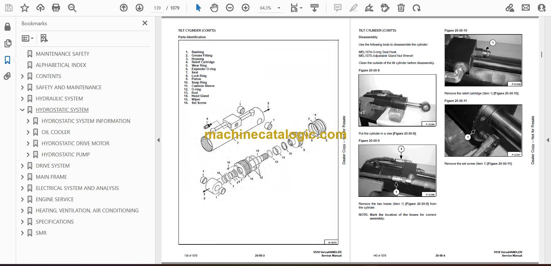
- Parts Identification
- Disassembly
- Assembly
- STEERING CYLINDER (FRONT) (For S/N 367611001 – 367612000 and S/N 367711001 – 367612000)
- Removal And Installation
- Parts Identification
- Disassembly
- Assembly
- STEERING CYLINDER (FRONT) (For S/N 367612001 & above, S/N 367712001 & above)
- Removing The Steering Cylinder
- Installing The Steering Cylinder
- Disassembling The Steering Cylinder
- Assembling The Steering Cylinder
- STEERING CYLINDER (REAR) (For S/N 367611001 – 367612000 and S/N 367711001 – 367712000)
- Removal And Installation
- Parts Identification
- Disassembly
- Assembly
- STEERING CYLINDER (REAR) (For S/N 367612001 and above, S/N 367712001 and above)
- Removing The Steering Cylinder
- Installing The Steering Cylinder
- Disassembling The Steering Cylinder
- Assembling The Steering Cylinder
- DRIVE BOX (For S/N 367611001 – 367612000 and S/N 367711001 – 367712000)
- Parts Identification
- Disassembly
- Inspection
- Assembly
- DRIVE BOX (S/N 367612001 & ABOVE, S/N 367712001 & ABOVE)
- Parts Identification
- Disassembly
- Assembly
- Special Tools
- MAIN RELIEF VALVE
- Testing And Adjustment
- Removal And Installation
- QUICK TACH CYLINDER
- Removal And Installation
- Parts Identification
- Disassembly
- Assembly
- PORT RELIEF VALVES
- STEERING MODE VALVE BLOCK
- Removal And Installation
- Parts Identification
- Disassembly
- Solenoid Testing
- Assembly
- BRAKE VALVE
- Removal And Installation
- Disassembly And Assembly
- GEAR PUMP
- Removal And Installation
- Parts Identification
- Disassembly And Assembly
- FAN MOTOR
- Removal And Installation
- Parts Identification
- Disassembly And Assembly
- HYDRAULIC RESERVOIR
- STEERING VALVE
- Removal And Installation
- Parts Identification
- Disassembly
- Inspection
- Assembly
- HYDRAULIC CONTROL VALVE
- Troubleshooting Chart (Controllers)
- Telescoping Valve Section Troubleshooting
- Auxiliary Valve Section Troubleshooting
- Troubleshooting Chart (Control Valve)
- Removal And Installation
- Parts Identification
- Disassembly And Assembly
- End Housing Disassembly And Assembly
- Lifting Valve Section Disassembly And Assembly
- Tilting Valve Section Disassembly And Assembly
- Telescoping Valve Section Disassembly And Assembly
- Auxiliary Valve Section Disassembly And Assembly
- Inlet-Outlet Valve Section Disassembly And Assembly
- JOYSTICK
- PARKING BRAKE
- Pressure Switch Removal And Installation
- Pressure Switch Disassembly And Assembly
- Parking Brake Valve Removal And Installation
- Parking Brake Valve Disassembly And Assembly
- PRESSURE REDUCING VALVE
- Testing
- Removal And Installation
- Disassembly And Assembly
- ACCUMULATOR
- TOW VALVE
- Removal And Installation
- Disassembly And Assembly
- FRONT AUXILIARY HYDRAULIC PRESSURE RELEASE VALVE
- Removal And Installation
- Disassembly And Assembly
- FLOW CONTROL VALVE
- HYDROSTATIC SYSTEM
- HYDROSTATIC SYSTEM INFORMATION
- Troubleshooting Chart
- Replenishing Valve Function
- OIL COOLER
- HYDROSTATIC DRIVE MOTOR
- Removal And Installation
- Parts Identification
- Disassembly
- Inspection
- Assembly
- HYDROSTATIC PUMP
- Removal And Installation
- Parts Identification
- Disassembly
- Inspection
- Assembly
- DRIVE SYSTEM
- TROUBLESHOOTING
- AXLE AND DIFFERENTIAL (FRONT) (FOR S/N 367611001 – 367612000 AND S/N 367711001 – 367712000)
- General Information
- Planetary Carrier Parts Identification
- Planetary Carrier Disassembly
- Planetary Carrier Inspection
- Wheel Hub Parts Identification
- Wheel Hub Disassembly
- Wheel Hub Inspection
- Steering Knuckle Parts Identification
- Steering Knuckle Disassembly
- Axle Housing/Drive Axle Parts Identification
- Axle Housing/Drive Axle Disassembly
- Brake Group Parts Identification
- Brake Group Disassembly
- Brake Group Inspection
- Differential Parts Identification
- Differential Disassembly
- Differential Inspection
- Pinion Group Parts Identification
- Pinion Group Disassembly
- Pinion Group Inspection
- Pinion Group Assembly
- Differential Assembly
- Brake Group Assembly
- Axle Housing/Drive Axle Assembly
- Steering Knuckle Assembly
- Wheel Hub Assembly
- Planetary Carrier Assembly
- AXLE AND DIFFERENTIAL (REAR) (For S/N 367611001 – 367612000 and S/N 367711001 – 367712000)
- General Information
- Planetary Carrier Parts Identification
- Planetary Carrier Disassembly
- Planetary Carrier Inspection
- Wheel Hub Parts Identification
- Wheel Hub Disassembly
- Wheel Hub Inspection
- Steering Knuckle Parts Identification
- Steering Knuckle Disassembly
- Axle Housing/Drive Axle Parts Identification
- Axle Housing/Drive Axle Disassembly
- Differential Parts Identification
- Differential Disassembly
- Differential Inspection
- Pinion Group Parts Identification
- Pinion Group Disassembly
- Pinion Group Inspection
- Pinion Group Assembly
- Differential Assembly
- Axle Housing/Drive Axle Assembly
- Steering Knuckle Assembly
- Wheel Hub Assembly
- Planetary Carrier Assembly
- AXLE AND DIFFERENTIAL (FRONT) (For S/N 367612001 & Above, S/N 367712001 & Above)
- General Information
- Planetary Carrier Parts Identification
- Planetary Carrier Disassembly
- Steering Knuckle Parts Identification
- Steering Knuckle Disassembly
- Brake System Identification
- Brake System Disassembly
- Differential Parts Identification
- Differential Disassembly
- Bevel Pinion Parts Identification
- Bevel Pinion Disassembly
- Bevel Pinion Assembly
- Differential Assembly
- Brake Assembly
- Steering Knuckle Assembly
- Planetary Carrier Assembly
- Special Tools
- AXLE AND DIFFERENTIAL (REAR) (FOR S/N 367612001 & ABOVE, S/N 367712001 & ABOVE)
- General Information
- Planetary Carrier Parts Identification
- Planetary Carrier Disassembly
- Steering Knuckle Parts Identification
- Steering Knuckle Disassembly
- Differential Parts Identification
- Bevel Pinion Parts Identification
- Bevel Pinion Disassembly
- Differential Assembly
- Steering Knuckle Assembly
- Planetary Carrier Assembly
- Special Tools
- FRONT AXLE (FOR S/N 367611001 – 367612000 and S/N 367711001 – 367712000)
- FRONT AXLE (FOR S/N 367612001 & ABOVE, S/N 367712001 & ABOVE)
- AXLE TOE-IN (FOR S/N 367611001 – 367612000 and S/N 367711001 – 367712000)
- AXLE TOE-IN (FOR S/N 367612001 & ABOVE, S/N 367712001 & ABOVE)
- PARKING BRAKE (FOR S/N 367611001 – 367612000 and S/N 367711001 – 367712000)
- Releasing The Brake For Towing
- Re-Activating The Brake
- PARKING BRAKE (FOR S/N 367612001 & ABOVE, S/N 367712001 & ABOVE)
- Releasing The Brake For Towing
- Re-Activating The Brake
- STEERING ANGLE ADJUSTMENT (FOR S/N 367611001 – 367612000 and S/N 367711001 – 367712000)
- STEERING ANGLE ADJUSTMENT (FOR S/N 367612001 & ABOVE, S/N 367712001 & ABOVE)
- DRIVESHAFT
- Removal And Installation (For S/N 367611001 – 367612000, S/N 367711001 – 367712000)
- Removal And Installation (For S/N 367612001 & Above, S/N 367712001 & Above)
- SERVICE BRAKE (FOR S/N 367611001 – 367612000 and S/N 367711001 – 367712000)
- Description
- Bleeding The Brake Circuit
- SERVICE BRAKE (FOR S/N 367612001 & ABOVE, S/N 367712001 & ABOVE)
- Description
- Bleeding The Brake Circuit
- REAR AXLE (FOR S/N 367611001 – 367612000 and S/ N 367711001 – 367712000)
- REAR AXLE (FOR S/N 367612001 & ABOVE, S/N 367712001 & ABOVE)
- MAIN FRAME
- OPERATOR CAB
- CANOPY
- OPERATOR SEAT
- BOOM ASSEMBLY
- INNER BOOM
- WEAR PADS (FRONT)
- WEAR PADS (REAR)
- ENGINE COVER
- Gas Cylinder Removal And Installation
- Removal And Installation
- AIR INTAKE COWLING
- FUEL TANK
- QUICK TACH
- REAR WEIGHTS
- FENDER
- Removal And Installation (For S/N 367611001 – 367612000 and S/N 367711001 – 367712000)
- Removal And Installation (For S/N 367612001 & Above, S/N 367712001 & Above)
- JOYSTICK PANEL
- DASH COVER/STEERING COLUMN COVER
- ELECTRICAL SYSTEM AND ANALYSIS
- ELECTRICAL SCHEMATICS
- ELECTRICAL SYSTEM INFORMATION
- Troubleshooting Chart
- Description
- Fuses, Diodes & Relays
- BATTERY
- Removal And Installation
- Servicing
- Using A Booster Battery (Jump Starting)
- ALTERNATOR
- Removal And Installation
- Adjusting The Alternator Belt
- STARTER
- Removal And Installation
- Parts Identification
- Disassembly
- Inspection And Repair
- Assembly
- LATERAL OPERATOR RESTRAINT SYSTEM (LOR’S™)
- Restraint Bar Removal And Installation
- Sensor Removal And Installation
- Strut Removal And Installation
- Strut Disassembly And Assembly
- Restraint Bar Bushing Removal And Installation
- Restraint Bar Bumper Removal And Installation
- LIGHTS
- Rear Light Removal And Installation
- Front Light Removal And Installation
- TRAVEL/SIGNAL LEVER
- INSTRUMENT PANEL
- SWITCH PANEL
- BRAKE LIGHT SWITCH
- Removal And Installation
- Adjustment
- FRONT WIPER MOTOR
- TOP WIPER MOTOR
- REAR WIPER MOTOR
- PEDAL ASSEMBLY
- Removal And Installation
- Disassembly And Assembly
- INCHING SWITCH
- Removal And Installation
- Adjustment
- SERVICE SOFTWARE
- Connecting The Laptop Computer
- Entering The Service Software
- Monitor Screen
- Warnings Screen
- Calibrate Inch Pedal
- Calibrate Creep Potentiometer
- Program/Update Susmic Controller
- ENGINE SERVICE
- TROUBLESHOOTING
- ENGINE SPEED CONTROL
- MUFFLER
- AIR CLEANER
- Housing Removal And Installation
- OIL COOLER/RADIATOR
- Removal And Installation
- Disassembly And Assembly
- ENGINE AND ENGINE MOUNTS
- ENGINE COMPONENTS AND TESTING
- Fuel Injection Pump Removal
- Fuel Injection Pump Installation
- Fuel Injectors Removal And Installation
- Checking The Fuel Lift Pump
- Fuel Lift Pump Removal And Installation
- Compression Checking
- Glow Plugs Checking
- Glow Plugs Removal And Installation
- ENGINE TIMING
- ENGINE/HYDROSTAT ASSEMBLY
- FLYWHEEL AND HOUSING
- Removal And Installation
- Ring Gear Removal
- Ring Gear Installation
- RECONDITIONING THE ENGINE
- Turbo Charger Troubleshooting
- Turbo Charger Description
- Turbo Charger Removal And Installation
- Exhaust Manifold Removal And Installation
- Fuel Injector Cover Removal And Installation
- Rocker Cover Removal And Installation
- Cylinder Head Removal
- Cylinder Head Inspection
- Cylinder Head Installation
- Rocker Shaft Disassembly And Assembly
- Valve Removal
- Valve Springs Checking
- Valve Depth Checking
- Valve Guides Checking
- Valve Guide Removal
- Valve Guide Installation
- Valves Checking
- Cutting A Valve Seat
- Valve Seat Assembly
- Changing Valve Springs (With Cylinder Head Installed)
- Valve Clearance Adjustment
- Timing Case And Drive Assembly Description
- Timing Cover Removal
- Timing Cover Installation
- Crankshaft Pulley Removal And Installation
- Front Oil Seal Removal And Installation
- Timing Case And Gear Removal
- Timing Case And Gear Installation
- Camshaft And Tappets Removal
- Camshaft And Tappets Installation
- Pistons And Connecting Rods Description
- Pistons And Connecting Rods Removal
- Pistons And Connecting Rods Disassembly
- Piston Ring End Gap
- Piston Ring Installation
- Piston Ring Groove Clearance
- Connecting Rod Inspection
- Connecting Rod Bushing Replacement
- Piston And Connecting Rod Assembly
- Piston And Connecting Rod Installation
- Checking Piston Height
- Crankshaft And Bearings Description
- Crankshaft And Bearings Removal
- Inspection Of Crankshaft And Bearings
- Crankshaft And Bearings Installation
- Rear Oil Seal Removal
- Rear Oil Seal Housing Positioning
- Rear Oil Seal Installation
- Checking Crankshaft End Play
- Cooling System Description
- Thermostat Removal and Installation
- Thermostat Testing
- Lubricating Oil Cooler Removal And Installation
- Water Pump Removal
- Water Pump Installation
- Engine Lubrication System Description
- Oil Filter Adapter Removal And Installation
- Oil Pan Removal And Installation
- Oil Screen And Pick-up Tube
- Oil Pump Removal
- Oil Pump Installation
- Oil Pump Disassembly And Assembly
- Oil Pressure Relief Valve Disassembly And Assembly
- Engine Block Description
- Engine Block Disassembly And Assembly
- Piston Cooling Jet Removal
- Piston Cooling Jet Installation
- Piston Cooling Jet Alignment
- Inspection
- Cylinder Liner Inspection
- Cylinder Liner Removal
- Cylinder Liner Installation
- HEATING, VENTILATION, AIR CONDITIONING
- AIR CONDITIONING SYSTEM FLOW
- COMPONENTS
- SAFETY
- REGULAR MAINTENANCE
- Filter Element Removal And Installation
- Compressor Drive Belt Inspection
- Cleaning The Condenser
- BASIC TROUBLESHOOTING
- Poor A/C Performance
- Compressor Drive Belt Inspection
- Checking The Electrical System
- GENERAL AIR CONDITIONING SERVICE GUIDELINES
- Compressor Oil
- Compressor Oil Check
- Component Replacement And Refrigeration Leaks
- SYSTEM TROUBLESHOOTING CHART
- Chart
- Gauge Pressure Related Troubleshooting
- TEMPERATURE/PRESSURE
- AIR CONDITIONING SERVICE
- SYSTEM CHARGING AND RECLAMATION
- Reclamation Procedure
- Charging Procedure With A Manifold Gauge Set
- Charging Procedure
- COMPRESSOR
- Removal And Installation
- Compressor Clutch Disassembly And Assembly
- CONDENSER
- RECEIVER/DRIER
- PRESSURE SWITCH
- EVAPORATOR/BLOWER UNIT
- EXPANSION VALVE
- HEATER ASSEMBLY
- Removal And Installation
- Fan Removal And Installation
- Core Removal And Installation
- SPECIFICATIONS
- VersaHANDLER SPECIFICATIONS
- Dimensional Specifications
- Performance Specifications
- Engine
- Controls
- Drive System
- Tires
- Capacities
- Hydraulic System
- Electrical System
- Instrument Panel
- ENGINE SPECIFICATIONS
- General
- Cylinder Head
- Valve Guides
- Exhaust Valves
- Intake Valves
- Valve Springs
- Rocker Shaft, Rockers And Bushings
- Pistons And Piston Rings
- Connecting Rods And Bearings
- Crankshaft
- Crankshaft Re-Grind Data
- Main Bearings
- Thrust Washers
- Camshaft And Thrust Washer
- Cylinder Block
- Cylinder Liners
- Fuel Injection Pump
- Fuel Injectors
- Fuel Lift Pump
- Timing Case And Timing Gears
- Oil Pump, Gear And Relief Valve
- Turbocharger
- Flywheel
- Water Pump And Thermostat
- Engine Torque Component
- MACHINE TORQUE SPECIFICATIONS
- TORQUE SPECIFICATIONS FOR BOLTS
- Torque for General SAE Bolts
- Torque For General Metric Bolts
- HYDRAULIC CONNECTION SPECIFICATIONS
- O-ring Face Seal Connection
- Straight Thread O-ring Fitting
- Tubelines And Hoses
- Flare Fitting
- O-ring Flare Fitting
- Port Seal Fitting
- HYDRAULIC/HYDROSTATIC FLUID SPECIFICATIONS
- CONVERSIONS
- Decimal And Millimeter Equivalents
- U.S. To Metric Conversion Chart
- SMR
- V518-1
- V518-2
- V518-3
- V518-4
- V518-5
- V518-6
- V518-7
Bobcat Software
Bobcat PDF Manuals


