Format: PDF (Printable Document)
File Language: English
File Pages: 396
File Size: 72.34 MB (Speed Download Link)
Brand: CNH
Model: 7200 P2075 Flex Hoe 900 Precision Hoe Dril
Part No: 92162340
Date: December 2024
Type of Document: Assembly Instructions
$ 55
1 SAFETY INFORMATION
Safety rules . . . . . . . . . . . . . . . . . . . . . . . . . . . . . . . . . . . . . . . . . . . . . . . . . . . . . . . . . . . . . . . . . . . . . . . . . . . . . . . . . 1-1
2 GENERAL INFORMATION
Torque . . . . . . . . . . . . . . . . . . . . . . . . . . . . . . . . . . . . . . . . . . . . . . . . . . . . . . . . . . . . . . . . . . . . . . . . . . . . . . . . . . . . . . 2-1
Torque – Standard torque data for hydraulic connections . . . . . . . . . . . . . . . . . . . . . . . . . . . . . . . . . . 2-6
3 ASSEMBLY
PRECISION HOE DRILL ASSEMBLY
Preparing for assembly . . . . . . . . . . . . . . . . . . . . . . . . . . . . . . . . . . . . . . . . . . . . . . . . . . . . . . . . . . . . . . . 3-1
Frame – Prepare Precision hoe drill for assembly . . . . . . . . . . . . . . . . . . . . . . . . . . . . . . . . . 3-1
Center section wheel hubs . . . . . . . . . . . . . . . . . . . . . . . . . . . . . . . . . . . . . . . . . . . . . . . . . . . . . . . . . . . 3-2
Caster wheels – Install The center section wheel hubs . . . . . . . . . . . . . . . . . . . . . . . . . . . . 3-2
Front hitch . . . . . . . . . . . . . . . . . . . . . . . . . . . . . . . . . . . . . . . . . . . . . . . . . . . . . . . . . . . . . . . . . . . . . . . . . . . . 3-4
Tongue or hitch Front hitch – Install The hitch assembly . . . . . . . . . . . . . . . . . . . . . . . . . . . 3-4
Center section wheels . . . . . . . . . . . . . . . . . . . . . . . . . . . . . . . . . . . . . . . . . . . . . . . . . . . . . . . . . . . . . . . 3-14
Caster wheels – Install The center section wheels . . . . . . . . . . . . . . . . . . . . . . . . . . . . . . . . 3-14
Inner and outer wing assembly . . . . . . . . . . . . . . . . . . . . . . . . . . . . . . . . . . . . . . . . . . . . . . . . . . . . . . 3-16
Frame – Install The universal joint . . . . . . . . . . . . . . . . . . . . . . . . . . . . . . . . . . . . . . . . . . . . . . . . 3-16
Frame – Install The inner boom . . . . . . . . . . . . . . . . . . . . . . . . . . . . . . . . . . . . . . . . . . . . . . . . . . . 3-17
Caster wheels – Install The inner wheel casters and tires . . . . . . . . . . . . . . . . . . . . . . . . 3-18
Frame – Install The outer wing . . . . . . . . . . . . . . . . . . . . . . . . . . . . . . . . . . . . . . . . . . . . . . . . . . . . 3-19
Frame – Paint The universal joint and wing hinge pins . . . . . . . . . . . . . . . . . . . . . . . . . . . 3-20
Caster wheels – Install The outer wing dual caster assembly . . . . . . . . . . . . . . . . . . . . 3-21
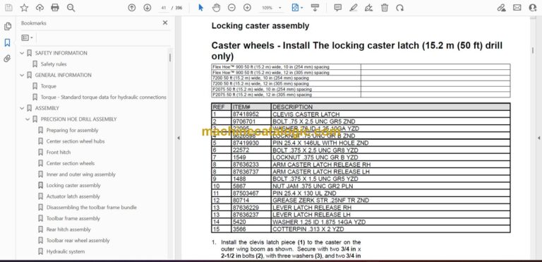
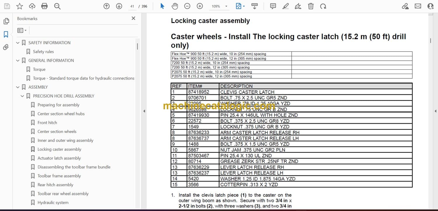
Locking caster assembly . . . . . . . . . . . . . . . . . . . . . . . . . . . . . . . . . . . . . . . . . . . . . . . . . . . . . . . . . . . . 3-23
Caster wheels – Install The locking caster latch (15.2 m (50 ft) drill only) . . . . . . . . 3-23
Caster wheels – Install The locking caster latch (18.3 m (60 ft), 21.3 m (70 ft), and 24.4
m (80 ft) drills only) . . . . . . . . . . . . . . . . . . . . . . . . . . . . . . . . . . . . . . . . . . . . . . . . . . . . . . . . . . . . . . . 3-30
Actuator latch assembly . . . . . . . . . . . . . . . . . . . . . . . . . . . . . . . . . . . . . . . . . . . . . . . . . . . . . . . . . . . . . 3-35
Transport locking assembly Swinging mechanical latch – Install The actuator latch arm
. . . . . . . . . . . . . . . . . . . . . . . . . . . . . . . . . . . . . . . . . . . . . . . . . . . . . . . . . . . . . . . . . . . . . . . . . . . . . . . . . . . . 3-35
Disassembling the toolbar frame bundle . . . . . . . . . . . . . . . . . . . . . . . . . . . . . . . . . . . . . . . . . . . . 3-37
Frame – Disassemble The toolbar frame bundle . . . . . . . . . . . . . . . . . . . . . . . . . . . . . . . . . . 3-37
Toolbar frame assembly . . . . . . . . . . . . . . . . . . . . . . . . . . . . . . . . . . . . . . . . . . . . . . . . . . . . . . . . . . . . . 3-41
Frame – Install The toolbar assembly . . . . . . . . . . . . . . . . . . . . . . . . . . . . . . . . . . . . . . . . . . . . . 3-41
Rear hitch assembly. . . . . . . . . . . . . . . . . . . . . . . . . . . . . . . . . . . . . . . . . . . . . . . . . . . . . . . . . . . . . . . . . 3-49
Tongue or hitch Rear hitch – Install The rear hitch hookup . . . . . . . . . . . . . . . . . . . . . . . 3-49
Toolbar rear wheel assembly . . . . . . . . . . . . . . . . . . . . . . . . . . . . . . . . . . . . . . . . . . . . . . . . . . . . . . . . 3-53
Rear wheel – Install . . . . . . . . . . . . . . . . . . . . . . . . . . . . . . . . . . . . . . . . . . . . . . . . . . . . . . . . . . . . . . . . 3-53
Hydraulic system . . . . . . . . . . . . . . . . . . . . . . . . . . . . . . . . . . . . . . . . . . . . . . . . . . . . . . . . . . . . . . . . . . . . 3-60
Hydraulic lines – Install locations and hose routing . . . . . . . . . . . . . . . . . . . . . . . . . . . . . . . 3-60
Cylinder – Install The hydraulic cylinders . . . . . . . . . . . . . . . . . . . . . . . . . . . . . . . . . . . . . . . . . 3-69
Folding control valve – Install The valve block assemblies . . . . . . . . . . . . . . . . . . . . . . . 3-76
Lines – Install The hydraulic system . . . . . . . . . . . . . . . . . . . . . . . . . . . . . . . . . . . . . . . . . . . . . . 3-78
Trips and openers . . . . . . . . . . . . . . . . . . . . . . . . . . . . . . . . . . . . . . . . . . . . . . . . . . . . . . . . . . . . . . . . . . 3-128
Lines – Install – Misc. hydraulic installation information . . . . . . . . . . . . . . . . . . . . . . . . . . 3-128
Hydraulic system . . . . . . . . . . . . . . . . . . . . . . . . . . . . . . . . . . . . . . . . . . . . . . . . . . . . . . . . . . . . . . . . . . . 3-130
Lines – Install – Misc. hydraulic installation information . . . . . . . . . . . . . . . . . . . . . . . . . . 3-130
Reservoir lines – Install – Correction to the center section openers lower circuit 3-132
Lines – Detailed view – Toolbar frame hydraulic hose installation – 50, 60, and 70 ft drills
. . . . . . . . . . . . . . . . . . . . . . . . . . . . . . . . . . . . . . . . . . . . . . . . . . . . . . . . . . . . . . . . . . . . . . . . . . . . . . . . . . . 3-133
Lines – Detailed view – Toolbar frame hydraulic hose installation – 80 ft drills . . . 3-209
Lines – Hydraulic schema. . . . . . . . . . . . . . . . . . . . . . . . . . . . . . . . . . . . . . . . . . . . . . . . . . . . . . . . . 3-245
Wing draft link assembly . . . . . . . . . . . . . . . . . . . . . . . . . . . . . . . . . . . . . . . . . . . . . . . . . . . . . . . . . . . 3-259
Frame – Install The wing draft link tubes . . . . . . . . . . . . . . . . . . . . . . . . . . . . . . . . . . . . . . . . . 3-259
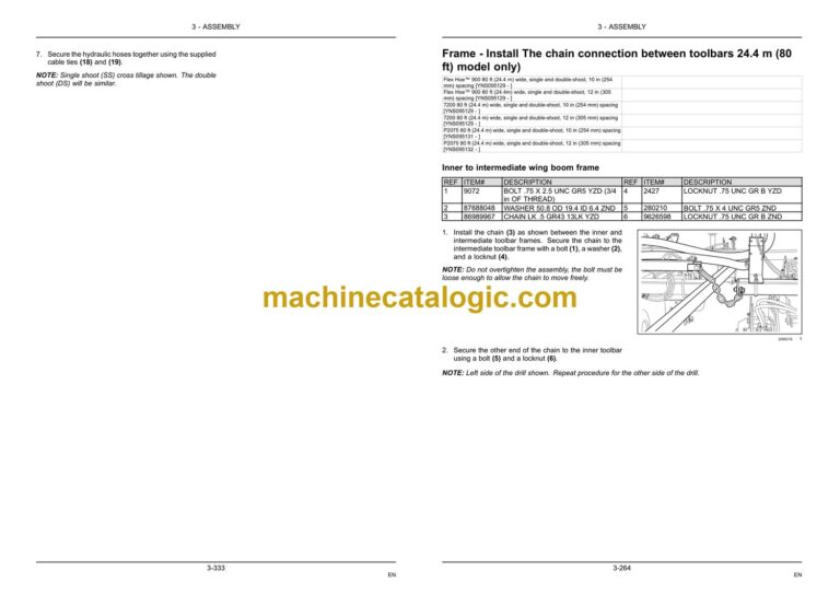
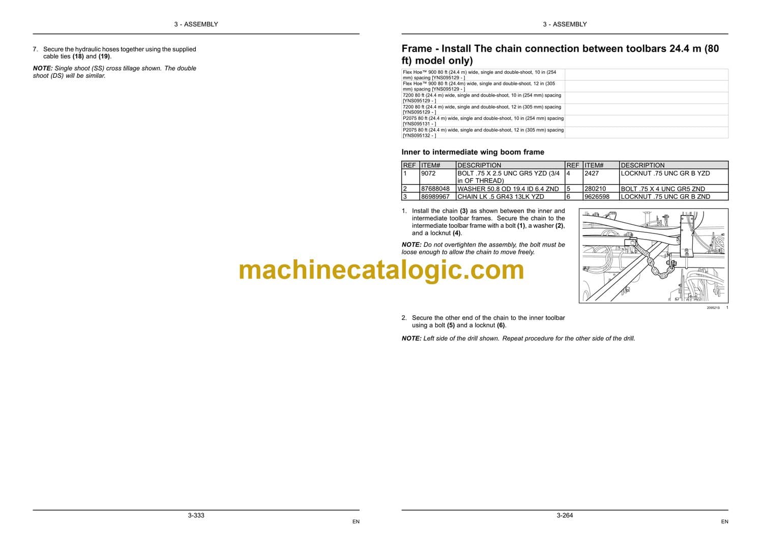
Toolbar chain connection . . . . . . . . . . . . . . . . . . . . . . . . . . . . . . . . . . . . . . . . . . . . . . . . . . . . . . . . . . . 3-261
Frame – Install The chain connection between toolbars 15.2 m (50 ft) model only ) 3-261
Frame – Install The chain connection between toolbars 18.3 m (60 ft) and 21.3 m (70
ft) model only) . . . . . . . . . . . . . . . . . . . . . . . . . . . . . . . . . . . . . . . . . . . . . . . . . . . . . . . . . . . . . . . . . . . . 3-262
Frame – Install The chain connection between toolbars 24.4 m (80 ft) model only) 3-264
Transport boom latch chain assembly. . . . . . . . . . . . . . . . . . . . . . . . . . . . . . . . . . . . . . . . . . . . . . 3-267
Frame – Install The transport boom latch chain . . . . . . . . . . . . . . . . . . . . . . . . . . . . . . . . . . 3-267
Reflectors, safety lighting & slow moving (SMV) emblem . . . . . . . . . . . . . . . . . . . . . . . . . . 3-271
External lighting – Install The transport lighting and slow moving vehicle sign (SMV)
. . . . . . . . . . . . . . . . . . . . . . . . . . . . . . . . . . . . . . . . . . . . . . . . . . . . . . . . . . . . . . . . . . . . . . . . . . . . . . . . . . . 3-271
Foldaway frame latch assembly . . . . . . . . . . . . . . . . . . . . . . . . . . . . . . . . . . . . . . . . . . . . . . . . . . . . 3-278
Frame – Install The foldaway frame latch cable assembly (18.3 m (60 ft) and 21.3 m
(70 ft) models only) . . . . . . . . . . . . . . . . . . . . . . . . . . . . . . . . . . . . . . . . . . . . . . . . . . . . . . . . . . . . . . 3-278
High draft weight (option). . . . . . . . . . . . . . . . . . . . . . . . . . . . . . . . . . . . . . . . . . . . . . . . . . . . . . . . . . . 3-280
Frame – Install The high draft weight kit (option) . . . . . . . . . . . . . . . . . . . . . . . . . . . . . . . . . 3-280
Toolbar locking pin storage location . . . . . . . . . . . . . . . . . . . . . . . . . . . . . . . . . . . . . . . . . . . . . . . . 3-283
Frame – Install The wing locking pins . . . . . . . . . . . . . . . . . . . . . . . . . . . . . . . . . . . . . . . . . . . . 3-283
Jack storage location . . . . . . . . . . . . . . . . . . . . . . . . . . . . . . . . . . . . . . . . . . . . . . . . . . . . . . . . . . . . . . . 3-285
Frame – Install The front hitch jack onto the storage location . . . . . . . . . . . . . . . . . . . . 3-285
Rear hitch assembly. . . . . . . . . . . . . . . . . . . . . . . . . . . . . . . . . . . . . . . . . . . . . . . . . . . . . . . . . . . . . . . . 3-287
Tongue or hitch Rear hitch – Install Hitch and hitch support . . . . . . . . . . . . . . . . . . . . . 3-287
Electronic Control Unit (ECU) . . . . . . . . . . . . . . . . . . . . . . . . . . . . . . . . . . . . . . . . . . . . . . . . . . . . . . 3-289
Electronic control – Install The ECU – Up to PIN YMS090000 . . . . . . . . . . . . . . . . . . . 3-289
Electronic control – Install The UCM – PIN YMS095001 and AFTER . . . . . . . . . . . . 3-290
Sensor and harness installation . . . . . . . . . . . . . . . . . . . . . . . . . . . . . . . . . . . . . . . . . . . . . . . . . . . . 3-291
Electronic control – Install The electronic harnesses and sensors . . . . . . . . . . . . . . . 3-291
Electronic control – Install The hose support strap . . . . . . . . . . . . . . . . . . . . . . . . . . . . . . . 3-300
Grease pivot points . . . . . . . . . . . . . . . . . . . . . . . . . . . . . . . . . . . . . . . . . . . . . . . . . . . . . . . . . . . . . . . . . 3-301
Frame pivot – Grease All pivot locations . . . . . . . . . . . . . . . . . . . . . . . . . . . . . . . . . . . . . . . . . 3-301
Hydraulic run-in sequence. . . . . . . . . . . . . . . . . . . . . . . . . . . . . . . . . . . . . . . . . . . . . . . . . . . . . . . . . . 3-305
Seeding auger hydraulic lines – Pressure test the hydraulic system . . . . . . . . . . . . . 3-305
Hydraulic systems – Check list . . . . . . . . . . . . . . . . . . . . . . . . . . . . . . . . . . . . . . . . . . . . . . . . . . . 3-314
ADJUSTMENTS
Initial machine leveling . . . . . . . . . . . . . . . . . . . . . . . . . . . . . . . . . . . . . . . . . . . . . . . . . . . . . . . . . . . . . 3-316
Frame – Adjust The air hoe drill leveling . . . . . . . . . . . . . . . . . . . . . . . . . . . . . . . . . . . . . . . . . 3-316
Adjustments . . . . . . . . . . . . . . . . . . . . . . . . . . . . . . . . . . . . . . . . . . . . . . . . . . . . . . . . . . . . . . . . . . . . . . . . 3-325
Frame – Adjust The transport boom latch . . . . . . . . . . . . . . . . . . . . . . . . . . . . . . . . . . . . . . . . 3-325
Caster wheels – Adjust The locking caster alignment . . . . . . . . . . . . . . . . . . . . . . . . . . . . 3-326
Tillage – Adjust The opener depth . . . . . . . . . . . . . . . . . . . . . . . . . . . . . . . . . . . . . . . . . . . . . . . 3-327
Wing/Boom traveling sensors – Adjust The system sensors . . . . . . . . . . . . . . . . . . . . . 3-328
Frame – Adjust. . . . . . . . . . . . . . . . . . . . . . . . . . . . . . . . . . . . . . . . . . . . . . . . . . . . . . . . . . . . . . . . . . . . 3-331
Cross tillage hydraulics . . . . . . . . . . . . . . . . . . . . . . . . . . . . . . . . . . . . . . . . . . . . . . . . . . . . . . . . . . . . . 3-332
Hydraulic systems – Assemble Cross tillage hydraulic hoses on a large hoe drill – for
50ft tow behind (TBH) drills . . . . . . . . . . . . . . . . . . . . . . . . . . . . . . . . . . . . . . . . . . . . . . . . . . . . . . 3-332
Hydraulic systems – Assemble Cross tillage hydraulic hoses and harnesses on a large
hoe drill – for 60, 70 and 80ft tow behind (TBH) drills . . . . . . . . . . . . . . . . . . . . . . . . . . . . 3-336
4 POST-ASSEMBLY
FINAL-CHECK
Final check . . . . . . . . . . . . . . . . . . . . . . . . . . . . . . . . . . . . . . . . . . . . . . . . . . . . . . . . . . . . . . . . . . . . . . . . . . . . . . . 4-1
Seeding – Product overview Post assembly checks . . . . . . . . . . . . . . . . . . . . . . . . . . . . . . . . . . . 4-1
Seeding – Product overview Post assembly check list . . . . . . . . . . . . . . . . . . . . . . . . . . . . . . . . . 4-2
Seeding – Product overview – Service parts cross reference list (FC) . . . . . . . . . . . . . . . . . 4-4
Seeding – Product overview – Service parts cross reference list (CIH) . . . . . . . . . . . . . . . 4-14
Seeding – Product overview – Service parts cross reference list (NH) . . . . . . . . . . . . . . . . 4-24

