$ 0
0
$ 0
0

Mustang 3200VT Compact Track Loader Operator Manual

Format: PDF (Printable Document)

File Language: English

File Size: 23.33 MB (Speed Download Link)

Brand: Mustang

Model: 3200VT

Machine Type: Compact Track Loader

Publication No.: 50940475 (Rev. L)

Edition Date: June 2021

Type of Document: Operator Manual (operation, controls, safety and routine maintenance)

Searchable: Yes, text is searchable and copyable

Delivery: Instant download after payment

Categories: ,

$ 40

Share:

Mustang 3200VT Compact Track Loader Operator Manual

Before anyone climbs into the 3200VT, send them to the Mandatory Safety Shutdown Procedure and the Before Starting pages in the Safety chapter. The Mustang 3200VT is a compact track loader, and this operator manual covers running it and looking after it.

It is publication number 50940475, Rev. L, dated June 2021, in English. It is written for the Mustang 3200VT and is handy when a used machine shows up with no book or a rental customer is taking one out for the first time.

What this manual helps you do

  • Start with the Delivery Checklists and Component Identification so a new operator knows where everything is before the key goes in.
  • Operate the machine by the During Operation and Parking the Machine sections, including Applications with Load-Handling Devices.
  • Check the Maintenance Schedule and keep the Maintenance Log up to date as service comes due.
  • Look up fluid types and capacities, the Coolant Compound Table and the SAE Torque Values when you are topping up or tightening.
  • Attach the standard attachments by following Using Attachments, and read Error Codes and Troubleshooting when a warning shows up.

Who this is for

Fits contractors and rental fleet managers who hand a 3200VT to a new operator and want a written reference to back up the walk-around. Owner-operators of a used machine can use it for daily checks and service intervals.

Print the Maintenance Log page for the cab and fill it in as you go.

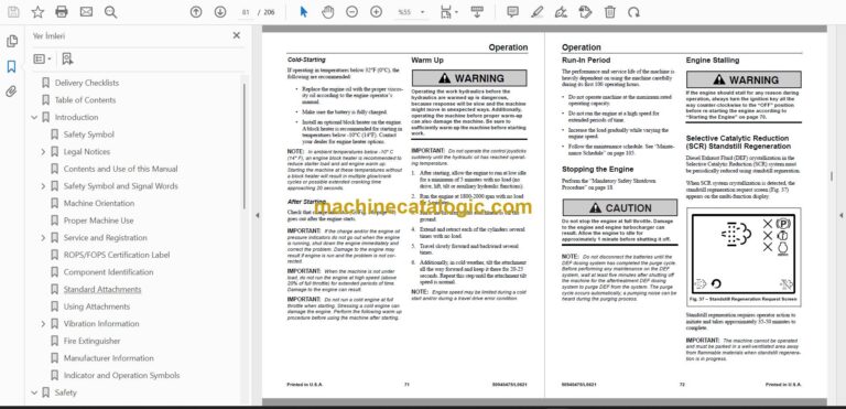
Preview of the Mustang 3200VT Compact Track Loader Operator Manual (PDF, sample pages)

Does this manual fit your machine?

Mustang model 3200VT
Machine type Compact Track Loader
Publication No. 50940475 (Rev. L)
Edition date June 2021

Check the model and serial number on your machine’s serial plate before ordering.

What’s inside

  • Wiring / electrical diagrams: Schematics; Electrical Schematic – Chassis (1 of 2) – (Mustang SN 0060301 and Up; All Manitou); Electrical Schematic – Chassis (2 of 2) – (Mustang SN 0060301 and Up; All Manitou)
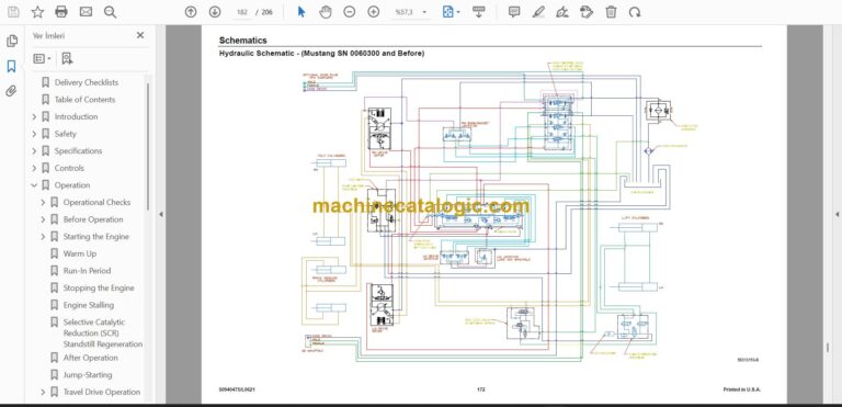
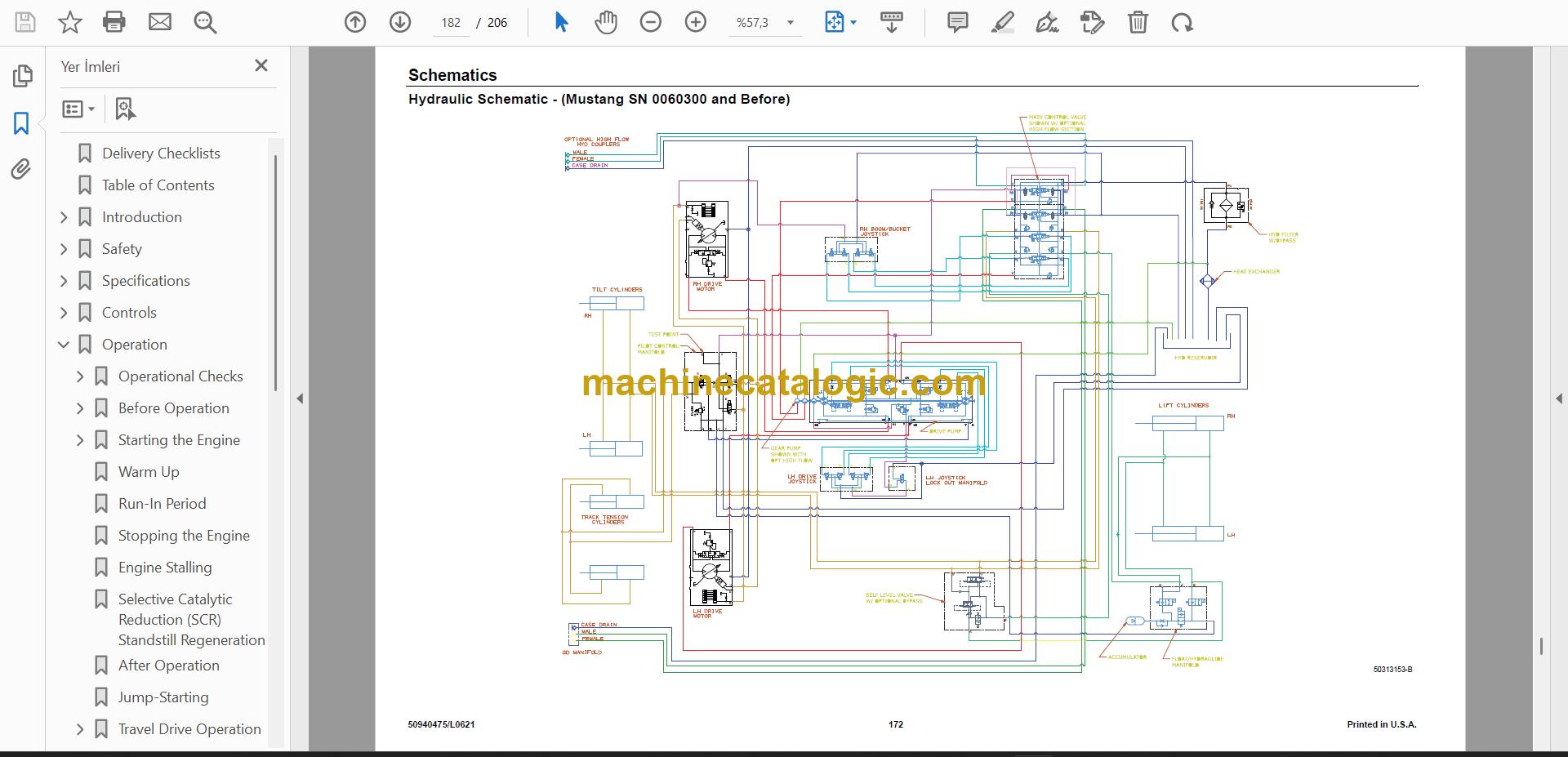
  • Hydraulic diagrams / schematics: Hydraulic Schematic – (Mustang SN 0060301 and Up; All Manitou); Hydraulic Schematic – (Mustang SN 0060300 and Before)
  • Fault / error codes: Error Codes; Engine Error Codes
  • Troubleshooting: Troubleshooting; Engine Troubleshooting; Seal and Hose Troubleshooting
  • Torque values: Torque Specifications; SAE Torque Values
  • Maintenance intervals / schedule: Maintenance Schedule; Maintenance Log
  • Lubrication, oils, fluids and capacities: Fluids/Lubricants Types and Capacities; Coolant Compound Table; Lubrication, Fluid and Filter Changes
  • Technical specifications: Specifications
  • Removal, installation and overhaul procedures: Swing-out Cab Door Removal; DEF Dosing Unit Filter Replacement; Track Replacement

FAQ

Where do I find how to lift or haul the machine?
Open the Transporting the Machine chapter. It has Lifting the Machine with a Crane and Loading and Transporting the Machine.

Does it help with fault codes?
Yes. There are Error Codes and Engine Error Codes sections, plus Troubleshooting, Engine Troubleshooting and Seal and Hose Troubleshooting.

Which serial numbers do the schematics cover?
The electrical and hydraulic schematics are marked for Mustang SN 0060301 and Up, which includes all Manitou. A separate hydraulic schematic covers SN 0060300 and Before.

Are any repair jobs described?
A few hands-on jobs are included, such as Track Replacement, Swing-out Cab Door Removal and DEF Dosing Unit Filter Replacement.

📘 Show Index

Table of Contents:

  • Delivery Checklists
  • Introduction
    • Safety Symbol
    • Legal Notices
      • Software IP
      • Data Privacy
    • Contents and Use of this Manual
    • Safety Symbol and Signal Words
      • Safety Alert Symbol
      • Signal Words
    • Machine Orientation
    • Proper Machine Use
    • Service and Registration
      • Machine Model and Serial Numbers
      • Component Serial Numbers
    • ROPS/FOPS Certification Label
    • Component Identification
    • Standard Attachments
    • Using Attachments
    • Vibration Information
      • Vibration Measurement and Actions
    • Fire Extinguisher
    • Manufacturer Information
    • Indicator and Operation Symbols
  • Safety
    • Safety Symbol and Signal Words
      • Safety Alert Symbol
      • Signal Words
    • Mandatory Safety Shutdown Procedure
    • Before Starting
    • During Operation
    • Applications with Load-Handling Devices
    • Parking the Machine
    • Electrical Energy
    • Maintenance and Service Safety Practices
    • Battery Hazards
    • Fire Hazards
    • Additional Safety Equipment
    • Crystalline Silica Exposure
    • Transporting the Machine
    • Lifting the Machine with a Crane
    • Loading and Transporting the Machine
    • Safety Decals
      • New Decal Application
    • ANSI-Style Safety Decals
    • ISO-Style Safety Decals
  • Specifications
    • Fluids/Lubricants Types and Capacities
    • Dimensions
    • Payloads/Capacities
    • Weights
    • Track Drive
    • Coolant Compound Table
    • Engine
    • Hydraulic System
      • General
      • Drive Hydraulics
      • Pumps
      • Cylinders
      • Forces and Cycle Times
    • Electrical System
    • Sound Power/Pressure Levels
    • Vibration Levels
    • Features
    • Standard Features
    • Optional Features
    • Common Materials and Densities
  • Controls
    • Multi-Function Display
      • Multi-Function Display Symbols
      • Multi-Function Display Screens
    • Control Buttons/Switches
    • Indicator Panel
      • Audible Alerts
    • Ignition Switch
    • Seat and Armrest/Joystick Console Adjustment
    • Control Joysticks
      • Left Joystick Functions
      • Right Joystick Functions
      • Joystick Buttons/Switch Functions
    • Parking Brake/Work Hydraulics Lock-out
    • Throttle Controls
    • ECO Mode Switch
    • Travel Controls
    • Lift Arm Float Button
    • Hydraglide™ Button
    • HVAC (Option)
    • Beacon/Work Lights
    • Wipers/Washers
      • Washer Fluid Reservoir
    • Battery Disconnect Switch (Option)
    • Rearview Camera (Option)
  • Operation
    • Operational Checks
      • Pre-Start Checks
      • Checks During Operation
      • Parking Checks
    • Before Operation
      • Cab Entry and Exit
      • Opening/Closing the Swing-Out Cab Door (Option)
      • Swing-out Cab Door Emergency Exit
      • Swing-out Cab Door Removal
      • Fold-up Door (Option)
        • Opening the Fold-up Door from the Outside
        • Closing the Fold-up Door from the Outside
        • Closing the Door from the Inside
        • Opening the Door from the Inside
      • Operator’s Seat
      • Seat Forward and Back Horizontal Adjustment
      • Seat Height Vertical Height/Weight Suspension Adjustment
        • Air Suspension
        • Mechanical Suspension
      • Seat Belt
      • Fastening/Unfastening the Seat Belt
      • Armrest/Joystick Console Adjustment
      • Parking Brake
        • Disengage Parking Brake
    • Starting the Engine
      • Cold-Starting
      • After Starting
    • Warm Up
    • Run-In Period
    • Stopping the Engine
    • Engine Stalling
    • Selective Catalytic Reduction (SCR) Standstill Regeneration
    • After Operation
    • Jump-Starting
    • Travel Drive Operation
      • Travel Drive Control Pattern
    • Rubber Track Use Cautions and Tips
      • Sprocket Tooth Wear and Track Life
    • Backup Alarm
    • Lift Arm Operation
      • Attachment Transport Position
      • Joystick Lift Arm Control Pattern
        • Lift Arm Operation Control Pattern
    • Self-Leveling
      • Self-Leveling Cancel
    • Lift Arm Float
    • Hydraglide™ Ride Control System
    • Hydraulics Control Lock
    • Lift Arm Support
      • Engage Lift Arm Support
      • Disengage Lift Arm Support
    • Connecting/Disconnecting Attachments
      • Connecting Attachments
      • Disconnecting Attachments
    • Hydraulically-Powered Attachments
      • Connecting Hydraulic Attachments to the Auxiliary Hydraulic Circuits
      • Disconnecting Hydraulic Attachments from the Auxiliary Hydraulics Circuit
      • Auxiliary Hydraulics Operation
        • Standard-Flow Auxiliary Hydraulics Control
        • High-Flow Auxiliary Hydraulics Control (Option)
    • 14-Pin Connector (Option)
      • Switch / Pin Assignments
    • Working with Buckets
      • Digging Tips
      • Working with Standard Buckets
        • Scooping
        • Loading
        • Digging
        • Backfilling
    • Working with Pallet Forks
      • Safety Instructions When Working with Pallet Forks
      • Transporting Loads Using Pallet Forks
        • Loading Pallet Forks
        • Lifting Loads Using Pallet Forks
        • Transporting Load Using Pallet Forks
        • Setting Down Loads Using Pallet Forks
    • Lifting the Machine using a Crane
      • Crane Lifting Preparation
    • Loading and Transporting the Machine on a Transport Vehicle
      • Loading and Securing the Machine
  • Maintenance
    • Maintenance Schedule
      • Checks, Cleaning and Inspection
      • Leakage Check
      • Lubrication, Fluid and Filter Changes
      • Functional Check
    • Engine Maintenance
      • Engine Access
        • Closing Engine Covers
      • Engine Oil
        • Checking Engine Oil Level
        • Changing Engine Oil and Filter
      • Engine Air Filters
      • Changing Air Filter Elements
      • Engine Cooling System
        • Checking Coolant Level
        • Cleaning Radiator Fins
        • Draining/Refilling Cooling System
      • Belt Maintenance
        • Engine Accessory Belt
        • Air Conditioning Belt
    • Diesel Exhaust Fluid (DEF) Service
      • Diesel Exhaust Fluid (DEF) Level
      • DEF Dosing Unit Filter Replacement
    • Fuel System Maintenance
      • Adding Fuel
      • Water Separator Inspection/Maintenance
      • Changing Water Separator and Fuel Filter
    • Hydraulic System Maintenance
      • Checking Hydraulic Oil Level
      • Changing Hydraulic Oil and Filter
    • Hydraulic Hose Maintenance
    • Travel Motor Maintenance
      • Travel Motor Gearbox Oil
    • Track Maintenance
      • Track Replacement
        • Track Installation
    • General Lubrication
    • Tilting ROPS/FOPS
      • Raising ROPS/FOPS
      • Lowering ROPS/FOPS
    • Electrical System
      • Battery
      • Using a Booster Battery (Jump-Starting)
      • Fuses and Relays
        • Fuses/Relays
      • Engine Compartment Relays/Fuses – (SN 821010 and Up, all Manitou Machines)
      • Engine Compartment Relays/Fuses – (SN 821009 and Before, not Manitou Machines)
        • Power-A-Tach Relay
        • Optional 14-Pin Connector Fuses/Relays
      • Rearview Camera Fuse
    • Long-Term Storage
      • Before Storage
      • After Storage
    • Air Conditioning Maintenance
      • Air Conditioning Filters
        • Cab Air Filter
        • Outside Air Intake Filter
    • Window Washer Reservoir
    • Side Window Removal
      • Side Front Window Removal
      • Side Rear Window Removal
      • Side Bottom Window Removal
    • Final Shutdown / Decommissioning
      • Before Disposal
      • Machine Disposal
    • Maintenance Log
  • Troubleshooting
    • Engine Troubleshooting
    • Indicator Troubleshooting
    • Seal and Hose Troubleshooting
    • Hydraulic System Troubleshooting
    • Hydrostatic Travel Drive System Troubleshooting
    • Electrical Troubleshooting
    • Error Codes
      • Engine Error Codes
  • Schematics
    • Hydraulic Schematic – (Mustang SN 0060301 and Up; All Manitou)
    • Hydraulic Schematic – (Mustang SN 0060300 and Before)
    • Electrical Schematic – Chassis (1 of 2) – (Mustang SN 0060301 and Up; All Manitou)
    • Electrical Schematic – Chassis (2 of 2) – (Mustang SN 0060301 and Up; All Manitou)
    • Electrical Schematic – Chassis (1 of 2) – (Mustang SN 0060300 and Before)
    • Electrical Schematic – Chassis (2 of 2) – (Mustang SN 0060300 and Before)
    • Electrical Schematic – Engine (1 of 2) – (Mustang SN 0060301 and Up; All Manitou)
    • Electrical Schematic – Engine (2 of 2) – (Mustang SN 0060301 and Up; All Manitou)
    • Electrical Schematic – Engine (1 of 2) – (Mustang SN 0060300 and Before)
    • Electrical Schematic – Engine (2 of 2) – (Mustang SN 0060300 and Before)
    • Electrical Schematic – Rear Door
    • Electrical Schematic – ROPS/FOPS
    • Electrical Schematic – Seat (1 of 2)
    • Electrical Schematic – Seat (2 of 2)
    • Electrical Schematic – Road Lights
    • Electrical Schematic – 14-Pin Connector
  • Index
  • EC Declaration of Conformity
  • Torque Specifications
    • SAE Torque Values

Mustang PDF Manuals

Related Manuals

0
0
Your Cart
Your cart is emptyReturn to Shop