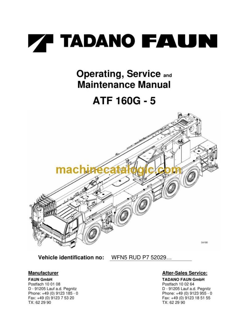
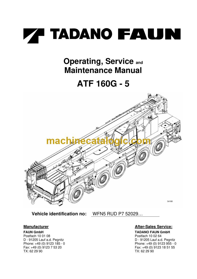
A Tadano ATF 160G-5 is a multi-axle all terrain crane that drives on public roads and then works on site with a telescopic boom. A workshop taking on a used crane that came without any paperwork is the buyer who gets the most from this set. You get every document for the machine in one download, so you're not chasing single books while the crane sits in your bay. The manual covers the ATF 160G-5 only.
What this manual set helps you do
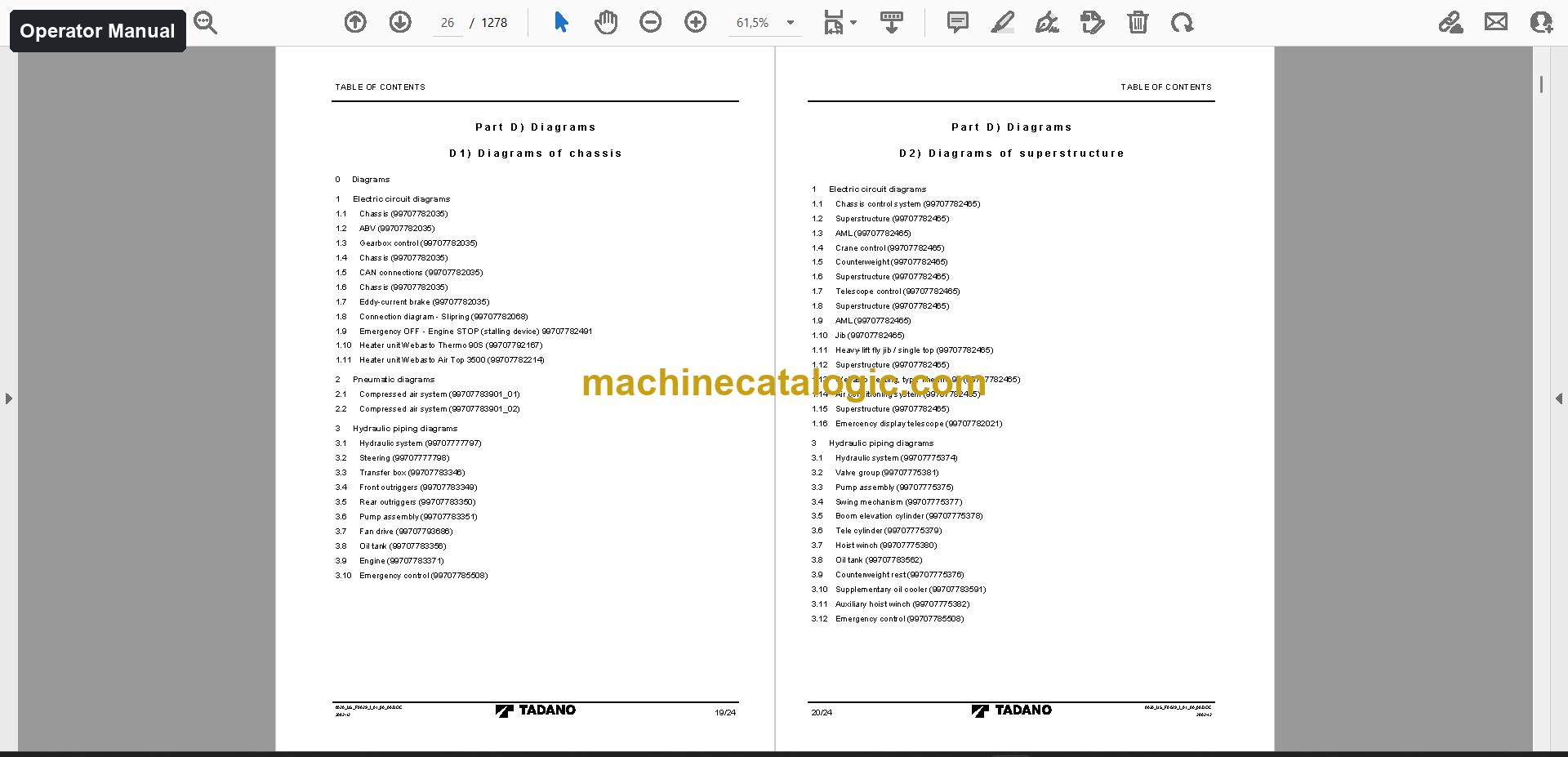
- Operate the crane correctly and run the daily checks from the operator manual, which has the controls, setup and safe operation for chassis and superstructure.
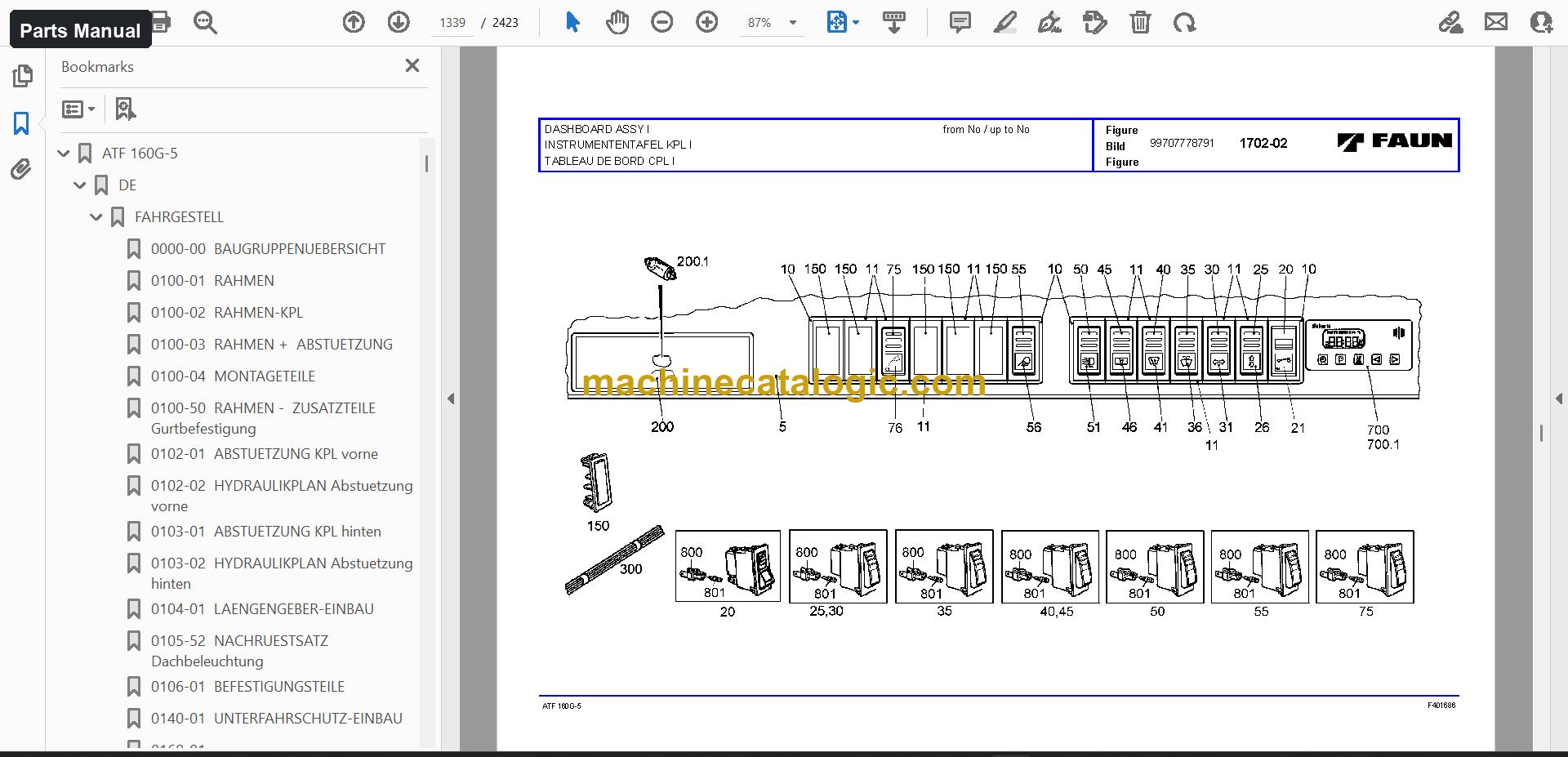
- Order the right parts from the parts manual, which has the exploded views and part numbers, including the axle parts list and spare parts list.
- Repair and troubleshoot chassis and CAN bus faults with the service manual, which covers adjustment and fault finding.
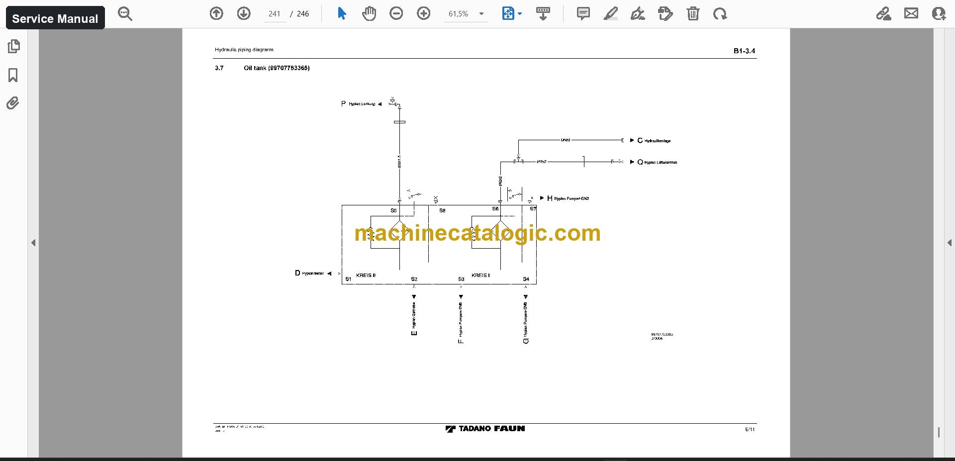
- Trace circuits using the schematics, 22 files with hydraulic and electrical drawings.
- Inspect the machine with the inspection forms, and check the Tadano AML-B Load Moment Indicator in the component manuals.
Who this is for
A workshop or service company taking in a used ATF 160G-5 gets the operator, parts, service and schematic documents in one place. A used crane dealer or exporter can hand the same set to the next owner along with the machine.
FAQ
Q: What do I receive and how is it organised?
A: One download with 163 files (139 PDF) and 13,087 PDF pages. The operator manual is 5,904 pages in 7 files (English, German), the parts manual is 5,612 pages in 5 files (German, English, French), and the service manual is 264 pages in 2 files (English). Technical data, service information, diagnostic documents and software, training documents and more are in the set too.
Q: Which machine does it fit?
A: The ATF 160G-5. The serial number on the main manual cover is WFN5 RUD P7 52029… and up, so you can match it against the plate on your crane.
Q: How does it help with a crane that arrived without paperwork?
A: You can start with the operator manual to learn the machine, use the service manual and schematics to find faults, and order parts from the parts manual. The diagnostic documents and inspection forms are there when you do the handover checks.
With the full set on your bench computer, you can take on the crane and work through it from first inspection to the parts order.
Does this manual fit your machine?
| Model |
Serial No. |
| ATF 160G-5 |
WFN5 RUD P7 52029… and up |
The serial number shown is the one printed on the manual cover. Check the model and serial number on your machine's data plate before ordering.
📘 Show Index
Table of Contents:
Operator Manual Table of Contents
5,904 pages, 7 files
Parts Manual Table of Contents
5,612 pages, 5 files
- Manual 2 (1,773 pages)
- GENERAL ARRANGEMENT ASSEMBLIES
- FRAME
- FRAME ASSY
- FRAME WITH SHORING
- MOUNTING PARTS
- SHORING ASSY front
- HYDRAULIC PLAN shoring front
- SHORING ASSY rear
- HYDRAULIC PLAN shoring rear
- FASTENING PARTS
- UNDERRIDE GUARD INSTALLATION
- SNATCH BLOCK HOLDER
- STEERING AXLE ASSY I 10×8
- AXLE HOUSING
- WHEEL BRAKE ASSY left
- WHEEL BRAKE ASSY right
- EXPANDER UNIT ASSY
- PLANETARY GEAR DRIVE
- AXLE DRIVE
- STEERING AXLE ASSY II 10×8
- RIGID AXLE ASSY III
- WHEEL BRAKE ASSY
- DRIVE 10×8
- STEERING AXLE ASSY IV
- STEERING AXLE ASSY V
- AXLE DRIVE ASSY
- AXLE INSTALLATION
- EDDY CURRENT BRAKE INST Telma
- EDDY CURRENT BRAKE ASSY
- POTENTIOMETER INSTALLATION
- RADIATOR INSTALLATION
- HYDRAULIC PLAN cooling water
- COOLING SYSTEM
- DRIVE UNIT INSTALLATION
- AIR CLEANER INSTALLATION
- DRY AIR CLEANER ASSY
- ENGINE
- DRIVE POWER UNIT ASSY
- ADDITIONAL PARTS engine
- WATER SEPARATOR INSTALLATION
- SPEED LIMITING 38km/h
- SPEED LIMITING 68km/h
- CLUTCH INSTALLATION
- POWER DIVIDER INSTALLATION
- POWER DIVIDER ASSY
- HYDRAULIC PLAN power divider
- POWER DIVIDER
- TRANSMISSION ASSY
- ACCESSORIES SET
- ADDITIONAL PARTS housing
- CONTROL UNIT
- CLUTCH DISENGAGER
- CONTROL VALVE
- HEAT EXCHANGER
- STEERING INSTALLATION
- HYDR PLAN, STEERING
- ANGLE GEAR INSTALLATION
- ANGLE GEAR INST driving possible
- ANGLE GEAR ASSY driving possible
- JOINT SHAFT INSTALLATION
- JOINT SHAFT INST without Telma
- JOINT SHAFT INST with Telma
- JOINT SHAFT INSTALLATION 10×8
- AUXILIARY CONTROL
- CONTROL SYSTEM
- CONTROL SYSTEM driving possible
- ROTARY LEADTHROUGH ASSY
- ROTARY LEADTHROUGH assembly of parts
- BRAKE CYLINDER INSTALLATION 1.axle
- BRAKE CYLINDER INSTALLATION 2.axle
- BRAKE CYLINDER INSTALLATION 3.axle
- BRAKE CYLINDER INSTALLATION 4.axle
- BRAKE CYLINDER INSTALLATION 5.axle
- AIR RESERVOIR INSTALLATION
- AIR RESERVOIR
- PNEUMATIC PLAN brake system
- PNEUMATIC PLAN accessories
- BRAKES ADD PARTS
- BRAKES ADD PARTS 3. Axle
- PNEUMATIC PLAN 10×8
- PNEUMATIC CONNECTION engine
- UNDER-CARRIER BRAKE
- BRAKE SYSTEM driving possible
- ANTILOCKING SYSTEM
- REPAIR PARTS
- ELECTRICAL SYSTEM
- CABLE HARNESS cab chassis
- CABLE HARNESS chassis
- CAB ELECTRIC SYSTEM
- DASHBOARD INSTALLATION
- DASHBOARD ASSY
- CABLE HARNESS dashboard
- DASHBOARD ASSY relay sheet I
- RELAY SHEET II
- ELECTRICAL ENGINE EQUIPMENT
- HEATER ASSEMBLY SET Thermo 90 S
- ELECTRICAL SYSTEM ABV
- ELECTR SYST day-time-driving-light
- PRIORITY LIGHT INSTALLATION yellow
- PRIORITY LIGHT INST "lightning" yellow
- BATTERY AND ACCESSORIES
- RADIO INSTALLATION
- COOLING CONTAINER INSTALLATION
- AIR CONDITIONER
- BACK-UP LIGHT INSTALLATION
- ELECTRICAL SYSTEM driving possible
- TACHOGRAPH INSTALLATION 2.driver, km/h
- TACHOGRAPH INSTALLATION 2.driver, mph
- EDDY CURRENT BRAKE Electric
- CONTROL BOX
- BORDER LIGHT INSTALLATION
- BORDER LIGHT INSTALLATION "NEW YORK"
- BORDER LIGHT INSTALL rear white-red
- LIGHT CARRIER INSTALLATION
- LIGHTING SUPPORTER ASSY left
- CABLE HARNESS ASSY front/left
- LIGHTING SUPPORTER ASSY right
- CABLE HARNESS ASSY right
- COVERING PART ASSY left
- COVERING PART ASSY right
- PLUG SOCKET INST trailer 24V
- ELECTRICAL SYSTEM 24V "USA"
- VIDEO INSTALLATION
- PLUG SOCKET INSTALLATION
- SWITCH INSTALLATION
- EXHAUST SYSTEM rustproof
- ENGINE HOOD INSTALLATION
- FRONT WALL ASSY
- REAR WALL ASSY
- HOOD COVER ASSY front
- HOOD COVER ASSY rear
- COVER ASSY
- SIDE WALL ASSY left
- COVER INSTALLATION
- PLATFORM INSTALLATION right
- PLATFORM INSTALLATION left
- FENDER INSTALLATION 3000 broad
- FENDER INSTALLATION 3200 broad
- FENDER INSTALLATION
- CONVERSION KIT fender 3000 broad (cab)
- MUD FLAP INSTALLATION
- FENDER – ADDITIONAL PARTS
- FUEL TANK INSTALLATION
- FUEL TANK ASSY
- TRAILER COUPLG INSTALLATION
- COUPLING INSTALLATION
- COUPLING INSTALLATION rear
- TIRE TYPES 16.00 R25 XGC Michelin
- TIRE TYPES 16.00 R25 VHS Bridgestone
- TIRE TYPES 20.50 R25 XGC Michelin
- WHEEL AND TIRE 20.50 R25 XGC Michelin
- TIRE TYPES 20.50 R25VHS Bridgestone
- WHEEL AND TIRE 20.50 R25 VHS Bridgestone
- TIRE TYPES 14.00 R25 XGC Michelin
- TIRE TYPES 14.00 R25 VHS Bridgestone
- TIRE TYPES 16.00 R25 Goodyear
- SPARE WHEEL CARRIER
- CAB ASSY
- CAB BODYSHELL
- GLAZING INSTALLATION
- SLIDING WINDOW ASSY left
- SLIDING WINDOW ASSY right
- CONSOLE INSTALLATION
- INSIDE LINING INSTALLATION
- WIPING AND WASHING SYSTEM
- WATER TANK INSTALLATION
- SEAT INSTALLATION
- SEATASSY left
- SEAT ASSY right
- DOOR INSTALLATION left/right
- DOOR ASSY left
- DOOR ASSY right
- FRONT COVERING INSTALLATION
- FRONT GATE INSTALLATION
- PEDAL ARRANGEMENT
- CAB EQUIPMENT
- SEAT ASSY left
- CAB (SPARE PART – TFG) 2700 broad
- CAB INSTALLATION
- MIRROR INSTALLATION
- MIRROR BRACKET left
- MIRROR BRACKET right
- CONVERSION KIT mirror 3200 broad
- ROOF INSTALLATION
- SWITCHBOARD INSTALLATION
- TOOLS + ACCESSORIES
- INSTRUM SUPPORT INSTALLATION
- DECAL KIT
- DECAL KIT "USA"
- DECAL KIT – INSTALLATION
- DECAL KIT "China"
- DECAL KIT Splash-water protection
- COVER INSTALLATION lower cab
- GUARD PLATE ASSY air conditioner
- COVER INSTALLATION air conditioner
- WHEEL CHOCK INSTALLATION
- FOOTSTEP INSTALLATION
- LICENSE BRACKET INSTALLATION
- LICENSE BRACKE INSTALLATION front/rear
- LICENSE BRACKET INSTALLATION rear "I"
- BATT BRACKET INSTALLATION
- BATTERY BOX ASSY
- LADDER INSTALLATION vehicle width 3000
- LADDER INSTALLATION vehicle width 3200
- LADDER INSTALLATION
- LADDER INSTALLATION front lh +rh
- CASE INSTALLATION
- CASE ASSY
- PLACE OF DEPOSIT at the tail
- PLACE OF DEPOSIT INSTALLATION
- HEATING INSTALLATION
- HEATER
- AUXIL HEATER INSTALLATION AT3500 D
- AUXIL HEATER INSTALLATION Thermo 90S
- HEATER Thermo 90S
- AIR CONDITIONER INSTALLATION
- COMPRESSOR INSTALLATION
- CONDENSER INST air conditioner
- CONDITIONER
- FUEL SYSTEM heating
- ENGINE PREHEATER
- CENTRAL LUBRICAT INSTALLATION 38 point
- CENTRAL LUBRICAT 38 point
- HYDRAULIC SYSTEM
- OIL RESERVOIR INSTALLATION
- OIL RESERVOIR ASSY
- HYDRAULIC PLAN OIL RESERVIOR
- PUMP INSTALLATION
- HYDRAULIC PLAN pump installation
- HOSE ACCESSORIES
- HYDRAULIC PLAN fan drive
- COVERING INSTALLATION left 3000 broad
- COVERING INSTALLATION left 3200 broad
- INSULATING-MAT SET
- SLIP RING ASSY
- SLEEPER BERTH INSTALLATION
- ANTISLIP INSTALLATION
- SAFETY MARKING
- COUNTERWEIGHT INSTALLATION
- COUNTERWEIGHT INST without 2.winch
- COOLING SYSTEM INSTALLATION
- COOLING SYSTEM delivery scope
- OIL COOLER INSTALLATION
- OIL COOLER INSTALLATION auxiliary
- AUXILIARY CONTROL Engine-stop
- ENGINE-SPARE PARTS
- PEDAL ARRANGEMENT driving possible
- AUXILIARY CONTROL crane upperstructure
- AUXILIARY CONTROL chassis
- AUXILIARY CONTROL general
- COMPR AIR SYSTEM driving possible
- CABLE HARNESS ASSY
- CABLE ASSY LML-Crane boom
- CABLE ASSY Telescopic control system
- CABLE ASSY slip ring
- HOUSING ASSY counterweight control sys
- RELAY INST counterweight control system
- CABLE ASSY ASLI-crane boom
- CAB ELECTRIC SYSTEM central electric
- CABLE HARNESS central electric
- CAB ELECTRIC SYSTEM standard equiment
- DASHBOARD ASSY I
- DASHBOARD ASSY II
- DASHBOARD ASSY III
- DASHBOARD ASSY IV
- MONITOR ASSY LCD 7
- CABLE HARNESS Dashboard I
- CABLE HARNESS dashboard II
- CABLE HARNESS dashboard III
- CABLE HARNESS Dashboard IV
- WORKING LIGHT INSTALLATION
- SPOT LIGHT ASSY
- WORKING LIGHT INST Xenon
- SPOT LIGHT ASSY Xenon
- ELECTRIC SYSTEM crane boom
- GROMMET HOUSING
- ANEMOMETER ASSY
- ELECTRICAL SYSTEM Delivery scope
- ADDITIONAL PARTS crane boom electric
- ELECTRICAL SYSTEM aircraft warning lamp
- CAB ELECTRIC SYSTEM Seat
- PRIORITY LIGHT INSTALLATION Winch
- PRIORITY LIGHT INSTALLATION 2.lamp
- CAB ELECTRIC SYSTEM AML timing
- FAN INSTALLATION
- CABLE ASSY
- WARNING SIGNAL INSTALLATION
- CAB ELECTRICAL SYSTEM
- CAB ELECTR SYSTEM driving possible
- RETROFIT KIT
- CAB ELECTR SYSTEM
- LIGHT INSTALLATION danger sign "F"
- VIDEO ISTALLATION
- OP HOUR COUNTER INSTALLATION winch
- EXHAUST SYSTEM
- SPARK ARRESTER INSTALLATION
- COVER INSTALLATION Engine
- COVER INSTALLATION left
- DRIVER INSTALLATION driving possible
- FUEL SYSTEM
- CRANE CAB
- PLATE INSTALLATION
- ROCKER operator´s panel
- SLIDING DOOR rigid
- OUTER DOOR PANEL
- WINDOW PANE
- REAR PANE
- ADDITIONAL PARTS
- INTERIOR EQUIPMENT
- ACTUATING ELEMENT
- PARTS KIT key
- CRANE CAB INSTALLATION
- MIRROR INSTALLATION shoring
- MIRROR INSTALLATION crane boom
- EQUIPMENT
- DANGER SIGN INSTALLATION "F"
- FIRE EXTINGUISH INSTALLATION
- FIRE-EXTINGUISH INSTALLATION
- HEATING INSTALLATION Thermo 90S
- HEATER Thermo 90S delivery scope
- HEATING INSTALLATION Thermo 90ST
- RETROFIT KIT air conditioner
- AIR CONDITIONER INST with spark arrester
- RETROFIT KITair conditioner
- ENGINE PREHEATER Calix
- CENTRAL LUBRICAT INSTALLATION
- CENTRAL LUBRICAT 12 point
- CENTRAL LUBRICAT 1 point
- CENTRAL LUBRICAT ACCESSORIES
- VALVE GROUP
- VALVE GROUP Delivery scope
- HYDRAULIC PLAN slewing gear drive
- HYDRAULIC PLAN slewinggear brake free
- HYDRAULIC PLAN hoisting winch
- HYDRAULIC PLAN derrick cylinder
- HYDRAULIC PLAN Derrick cylinder free
- HYDRAULIC PLAN Telescopic boom
- HYDRAULIC PLAN Lock Telescopic Cylinder
- HYDRAULIC PLAN counterweight
- HYDRAULIC PLAN oil reservoir
- MEASURNEMENT TRANSDUCER INST
- DOLLY SELECTION
- DERRICK CYLINDER INSTALLATION
- CRANE UPPERSTRUCTURE INSTALLATION
- TELESCOPIC BOOM ASSY
- BASIC BOOM ASSY
- CRANE BOOM ASSY 1
- CRANE BOOM ASSY 2
- CRANE BOOM ASSY 3
- CRANE BOOM ASSY 4
- CRANE BOOM ASSY 5
- SLEWING GEAR INSTALLATION
- SWIVEL BEARING INSTALLATION
- LOCK INSTALLATION
- HYDRAULIC PLAN Cran superstructure
- FOLDING JIB INSTALLATION
- FOLDING JIB 5,4m Delivery scope
- FOLDING JIB ASSY 5,4m
- FOLDING JIB ASSY 5,4m Electric
- PULLEY CARRIER INSTALLATION
- PULLEY CARRIER ASSY
- JIB POINT INSTALLATION 7,5m
- JIB POINT 7,5m Delivery scope
- JIB POINT ASSY 7,5m
- JIB POINT ASSY 7,5m Electric
- SECTION INSTALLATION 6m
- SECTION ASSY 6m
- BOOM-DERRICK CYL DISMANTLING
- BOOM-DISMANTLING
- DERRICK ZYLINDER-DISMANTLING
- HYDRAULIC PLAN boom dismantling
- ELECTRICAL SYSTEM boom-dismantling
- CABLE HARNESS ASSY boom-dismantling
- HOUSING ASSY
- HEAVY PULLEY INSTALLATION
- HEAVY PULLEY ASSY
- LMB INSTALLATION AML
- LMB INSTALLATION AML "USA"
- HOOK BLOCK 25t single hook
- HOOK BLOCK 63t single hook
- HOOK BLOCK 63t double hook
- HOOK BLOCK 80t double hook
- HOOK BLOCK 80t single hook
- HOOK BLOCK 125t double hook
- HOOK BLOCK 160t double hook
- CRANE HOOK 10t
- FRONT BUILD PULLEY INSTALLATION
- FRONT BUILD PULLEY ASSY
- FRONT BUILD PULLEY ASSY Electric
- HOISTING WINCH INSTALLATION
- WINCH ASSY
- MULTIPLE DISC BRAKE
- HOISTING WINCH INSTALLATION 2.winch
- HYDRAULIC PLAN 2.winch
- HOISTING WINCH INST Electric 2.winch
- COUNTERWEIGHT INST balance 2.winch
- HOISTING WINCH INST 2.winch without winc
- TURN INDICAT INSTALLATION
- PULLEY INSTALLATION
- IDLER PULLEY ASSY
- TELESCOPIC CYLINDER Delivery scope
- TELESCOPIC CYLINDER ASSY
- HYDRAULIC CYLINDER ASSY
- CYLINDER ASSY
- CABLE DRUM ASSY
- INDICATOR GAUGE AML
- TEST APPARATUS AML-BB
- INDICATOR GAUGE AML "USA"
- LOWERING BRAKE VALVE ASSY
- CHECK VALVE ASSY
- PRESSURE RELIEF VALVE ASSY
- SOLENOID VALVE ASSY
- HOSE REEL ASSY
- RESERVOIR
- SOLENOID VALVE 5/2 ASSY
- AXIAL PISTON MOTOR
- RELAY VALVE ASSY
- BRAKE VALVE ASSY
- FLOW INDICATOR ASSY
- BLEED VALVE ASSY
- STEER CYLINDER ASSY
- STEER CYLINDER
- MULTI WAY VALVE 6/2
- MULTI WAY VALVE 4/2
- FILLER TUBE ASSY
- CONTROL BLOCK ASSY
- REFRIGERANT LINE
- SUSPENSION CYLINDER ASSY
- CABLE DRUM
- COMPRESSED-AIR PURIFYNG DRYING ASSY
- SOLENOID VALVE 3/2
- CONDENSOR
- CONTROL BLOCK
- AXIAL PISTON PUMP ASSY
- SLIP RING BULK ASSY
- RETURN FLOW FILTER ASSY
- HYDR ACCUMULATOR ASSY
- AIR DEHUMIDIFIER ASSY
- AXIAL PISTON ASSY
- SHORING CYLINDER
- EXTENDING CYLINDER ASSY
- MULTI WAY VALVE -3/2 ASSY
- RADIAL PISTON ASSY
- CONTROL VALVE ASSY
- ADJUSTER ASSY
- PUMP ASSY
- BRACKET ASSY
- BRAKE CYLINDER ASSY
- LOCK ASSY
- STEERING ROD ASSY
- ANGLE GEAR ASSY
- WEIGHT ASSY with bracket
- DOOR HANDLE ASSY
- TORQUE STRUT ASSY
- SUPPORT PLATE ASSY
- SOCKET PIN ASSY
- SOCKET PIN
- FILLER TUBE
- PROXIMITY SWITCH CPL
- HYDRAULIC CYLINDER
- EXTENDING CYLINDER
- DERRICK CYLINDER
- SLEWING GEAR DRIVE ASSY
- ROLLER RETAINER ASSY
- CHAIN ASSY extend
- CHAIN ASSY carry in
- STEERING GEAR ASSY
- JOINT SHAFT
- COUPLING
- WATER SEPARATOR ASSY
- CARDAN SHAFT BEARING
- LIGHT ASSY
- GUIDE FRAME ASSY
- TRANSPORT SUPPORT IN ASSY
- AXIAL PISTON MOTOR ASSY
- BALL JOINT
- BRAKE CYLINDER
- COUPLING HEAD color of cover red
- COUPLING HEAD color of cover yellow
- Manual 1 (3,836 pages)
- FAHRGESTELL
- BAUGRUPPENUEBERSICHT
- RAHMEN
- RAHMEN-KPL
- KRAN
- BAUGRUPPENUEBERSICHT
- GEGENGEWICHT EINBAU
- GEGENGEWICHT EINBAU ohne 2.Winde
- ANHANG
- UMLENKROLLE KPL
- TELESKOPZYLINDER Lieferumfang
- TELESKOPZYLINDER KPL
- CHASSIS
- GENERAL ARRANGEMENT ASSEMBLIES
- FRAME
- FRAME ASSY
- CRANE
- GENERAL ARRANGEMENT ASSEMBLIES
- COUNTERWEIGHT INSTALLATION
- COUNTERWEIGHT INST without 2.winch
- ANNEX
- IDLER PULLEY ASSY
- TELESCOPIC CYLINDER Delivery scope
- TELESCOPIC CYLINDER ASSY
- GRUE
- GROUPES ENEMBLES
- CONTREPOIDS INSTALLATION
- CONTREPOIDS INST sans 2.treuil
- ANNEXE
- POULIE DE RENVOI CPL
- CYL TELESCOPIQU Emprise de livraison
- CYLINDRE TELESCOPIQU CPL
- Manual 3 (3 pages)
Service Manual Table of Contents
264 pages, 2 files
- Publication B.1 (246 pages)
- CMV
- Main Screen
- Selection Menu
- Working Menu
- CGM
- Control Panel
- Start Screen
- Main Menu
- CGC
- Main Screen
- Selection Menu
- Working Menu
- CAN BUS
- CAN Icon in Main Screen
- Error Codes in the CMV
- Error Code Display via Hyper Terminal
- CAN BUS Pin Assignment
- D017 CGM Driver's Side
- D015 CGM Passenger's Side
- CGC Superstructure
- CAN BUS Rear Steering
- Software Download
- Parameter Download
- Steering Potentiometer Reset
- CAN BUS Software Specification Explanation of Functions
- Functions D001/D002 Nodes
- Functions D003/D004 Nodes
- Functions D005/D006 Gate
- Overview
- Layout of Components
- Connection Diagram
- Drivers Cab
- Instrument Panel
- Behind Front Cover
- Electric Components Inside Cab
- Electric System
- Hydraulic System
- Pump
- Priority Valve
- Fan System
- Pneumatic System
- Key for Diagrams
- Assumption in Electrical Circuit Diagrams
- Electrical Circuit
- Electrical Circuit ~#2035110
- Electrical Circuit #2035111~
- Hydraulic Circuit
- Hydraulic System
- Steering
- Motor
- Pneumatic Circuit
- Brake System
- Auxiliary Equipment
- Anti-Lock System
- Publication 99707782385 (18 pages)
- CAN icon in main screen
- Error codes indicated in the CMV colour display
- Error code screen
- Engine error code screen
- Reset “3rd axle: Lift – Lower – Lifted”
- Error code display via Hyper terminal
- Checking the inputs and outputs
- Optionen
- All Outputs
- All Inputs
- CAN DESIGN
- Fuses
Also in this set
- Schematics (22 files, 384 pages)
- Technical data (49 files, 203 pages)
- Service information (18 files, 76 pages)
- Assembly and installation (2 files, 7 pages)
- Diagnostic documents and software (32 files, 371 pages)
- Training documents (2 files, 26 pages)
- Inspection forms (4 files, 18 pages)
- Component manuals (10 files, 210 pages)
- Tadano AML-B Load Moment Indicator
- Other documents (10 files, 12 pages)
Tadano PDF Manuals
All Crane Manuals